lecture 13-15: transmission media aliazam abbasfar
TRANSCRIPT

EE354 : Communications System I
Lecture 13-15: Transmission media
Aliazam Abbasfar

OutlineTransmission media

Communications systemsWireline (wired)
Telephony (voice, fax, modem, DSL) Ethernet/LAN Cable TV Backplane copper links
Wireless (Electromagnetic) Over the air communication Radio and TV broadcast WLAN Cellular Radar
Fiber optics High speed long haul data communication High traffic data transfer
Transmission mediaOpen wire
Twisted pair
Coaxial cable
Optical fiber
Air

Open-wire
On utility poles share power line routes
Interference limited (EMI)Limits the BW too
Transposition to reduce interferenceEarly twisting scheme4 twists per Km
Environmental effects

Twisted pair cableUnshielded twisted pair (UTP)
Shielded twisted pair (STP)

Transmission parameters• Lumped model• for a unit length
• System response H(f) = e-gL = + g a j b =
Loss (dB) = 20 log10e a L = a’ L
phase change = b L
• Loss increases with frequency
))(( jCGjLR
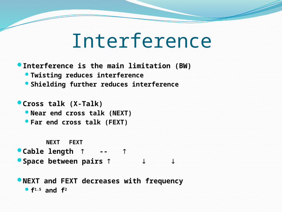
Interference Interference is the main limitation (BW)
Twisting reduces interference Shielding further reduces interference
Cross talk (X-Talk) Near end cross talk (NEXT) Far end cross talk (FEXT)
NEXT FEXT
Cable length -- Space between pairs
NEXT and FEXT decreases with frequency f1.5 and f2

ApplicationsCommunication networks
Subscriber lines Analog (Voice) Digital (ADSL, HDSL, VDSL)
Links (E1,T1)
Computer networksLAN
Cat 3 < 10 Mbps Cat 4 < 100 Mbps Cat 5 < 150 Mbps Cat 6 < 350 Mbps
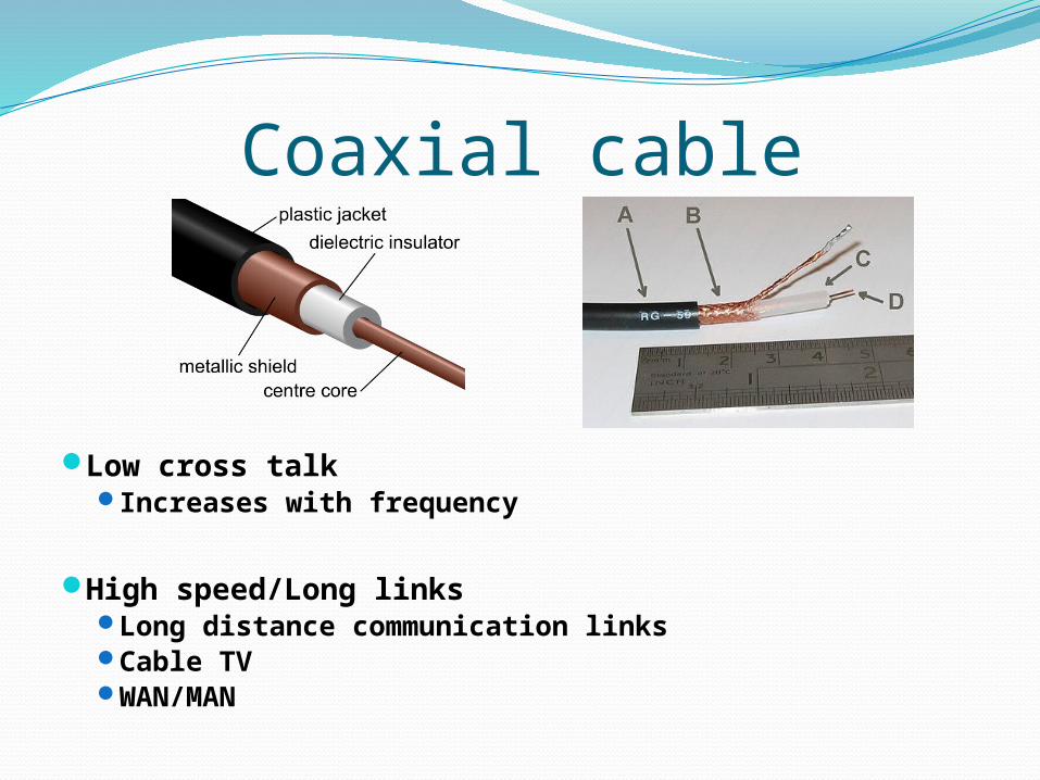
Coaxial cable
Low cross talk Increases with frequency
High speed/Long linksLong distance communication linksCable TVWAN/MAN
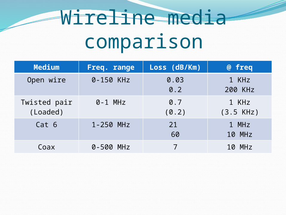
Wireline media comparisonMedium Freq. range Loss (dB/Km) @ freq
Open wire 0-150 KHz 0.030.2
1 KHz200 KHz
Twisted pair(Loaded)
0-1 MHz 0.7(0.2)
1 KHz(3.5 KHz)
Cat 6 1-250 MHz 21 60
1 MHz10 MHz
Coax 0-500 MHz 7 10 MHz

Optical FiberStructure
1. Core (8 µm)2. Cladding (125 µm)3. Buffer (250 µm)4. Jacket (400 µm)
Optical cable

Fiber opticsOptical propagation
Refraction indexncore > ncladding
Fiber typesStep indexGraded index
Single modeMulti mode

Optical fiber Loss
Absorption Scattering Connectors
Low loss : 0.2 dB/Km Color dependent
Dispersion Multi modes = different paths Refraction index is frequency (color) dependent
High bandwidth ( > 1 GHz)
Wavelength division multiplexing (WDM) DWDM Data rate > TB/s in a single fiber !

Wireless communication Frequency allocation needed in shared environment
To avoid interference Spectrum is a very valuable resource
Band allocation to applications Government regulations and policies ITU coordinates between nations
Freq band: 3-30KHz Very low freq. (VLF) 30-300KHz Low freq. (LF) 300K-3MHz Medium freq. (MF) 3-30MHz High freq (HF) 30-300MHz Very high freq (VHF) 300M-3G Ultra high freq (UHF) 3-3GHz Super high freq. (SHF)

Electromagnetic waves propagationsGround waves travels along the
surface of the earth ( freq < 2 MHz)
Sky waves reflected by ionosphere Very variable – seasonal
Angle and loss of reflection Freq < 30 MHz
Line of sight (LOS) No reflection or refraction
Non Line of sight Local reflections/refractions

Wireless issuesPath loss
Fading
Mobility
Interference

Satellite systems LEOs
Lower power Smaller delay Need many satellites
Shift towards LEOs in 1990 Global domination Compete with cellular systems Failed miserably (Iridium )
Big, power hungry mobile terminals
Global Positioning System (GPS) Satellite signals used to pinpoint location Popular in cars, cell phones, and navigation devices
Natural area for satellite systems is broadcasting Now operate in 12GHz band 100s of TV and radio channels All over the world

ReadingCarlson Ch. 1
Proakis Ch. 1