lecture # 15: aircraft and wind turbine icing and anti-/de...
TRANSCRIPT

Copyright © by Dr. Hui Hu @ Iowa State University. All Rights Reserved!
Dr Hui Hu
Dr Rye M Waldman
Department of Aerospace Engineering, Iowa State University
Ames, Iowa 50011, U.S.A
Lecture # 15: Aircraft and wind turbine icing and anti-/de-icing
AerE 344 Lecture Notes

Copyright © by Dr. Hui Hu @ Iowa State University. All Rights Reserved!
Ice accretion on wings
Atmospheric moisture freezes on wings
•Accreted ice modifies airfoil shape
•Increases drag
•Can lead to stall
•Costly to remove
Conditions determine ice type (glaze vs rime)
•Liquid water content (LWC)
•Temperature
•Airspeed
•Geometry
•Surface chemistry
Introduction

Copyright © by Dr. Hui Hu @ Iowa State University. All Rights Reserved!
Wind Turbine Icing and Anti-/De- Icing
• Wind turbine icing represents the most significant threat to the integrity of wind turbines in cold weather.
– Change airfoil shapes of turbine blades. – Cause imbalance to the rotating system. – Shedding of large chuck of ice can be dangerous to public safety. – Cause errors to anemometers to estimate wind resource.
• Some thermal de-icing systems could consume up to 70% of the total power generated by the wind turbine on cold days.

Copyright © by Dr. Hui Hu @ Iowa State University. All Rights Reserved!
Zhang et al., 2014
Basic icing problem
Fortin et al., 2005
Mass
Energy
U
LWC, D, T
Rothmayer, 2003 Shin & Bond, 1994 Tsao & Lee, 2012

Copyright © by Dr. Hui Hu @ Iowa State University. All Rights Reserved!
• Glaze ice is the most dangerous type
of ice.
• Glaze ice form much more
complicated shapes and are difficult to
accurately predict.
• Glaze ice is much more difficult to
remove once built up on aircraft wings
or wind turbine blades.
Rime Ice and Glaze Ice
a)
b)
Oncoming air
flow with
supercooled
water droplets
Glaze ice formation
Rime ice formation

Copyright © by Dr. Hui Hu @ Iowa State University. All Rights Reserved!
ISU Icing Research Tunnel
ISU-Icing Research Tunnel (ISU-IRT)
• The ISU Icing Research Tunnel (ISU-IRT), originally donated by
UTC Aerospace System ( formerly Goodrich Corp.), is a research-
grade multi-functional icing wind tunnel.
• The working parameters of the ISU-IRT include:
• Test section: 16 inches by 16 inches by 6 ft
• Velocity: up to 60m/s;
• Temperature: down to -30 OC;
• Droplet Size: 10 to 100 micrometers;
• Liquid Water Content (LWC): 0.05 ~ 20 grams/cubic meter.
• The large LWC range allows ISU-IRT tunnel to be run over a
range of conditions from rime ice to extremely wet glaze ice.

Copyright © by Dr. Hui Hu @ Iowa State University. All Rights Reserved!
Experimental conditions:
smV /20~10
min/0.1 mlQ
Incoming flow velocity:
Water flow rate:
Spray droplet size: 50um~10D
Incoming
flow
Digital image
projector Digital camera
Spray nozzles
Water droplets
NACA0012 airfoil
Picture of the test section in the icing wind tunnel
Wind-driven Water Runback Flow over a NACA 0012 Airfoil
(Zhang K. and Hu H., AIAA-2014-0741, 2014)
Copyright © by Dr. Hui Hu @ Iowa State University. All Rights Reserved!
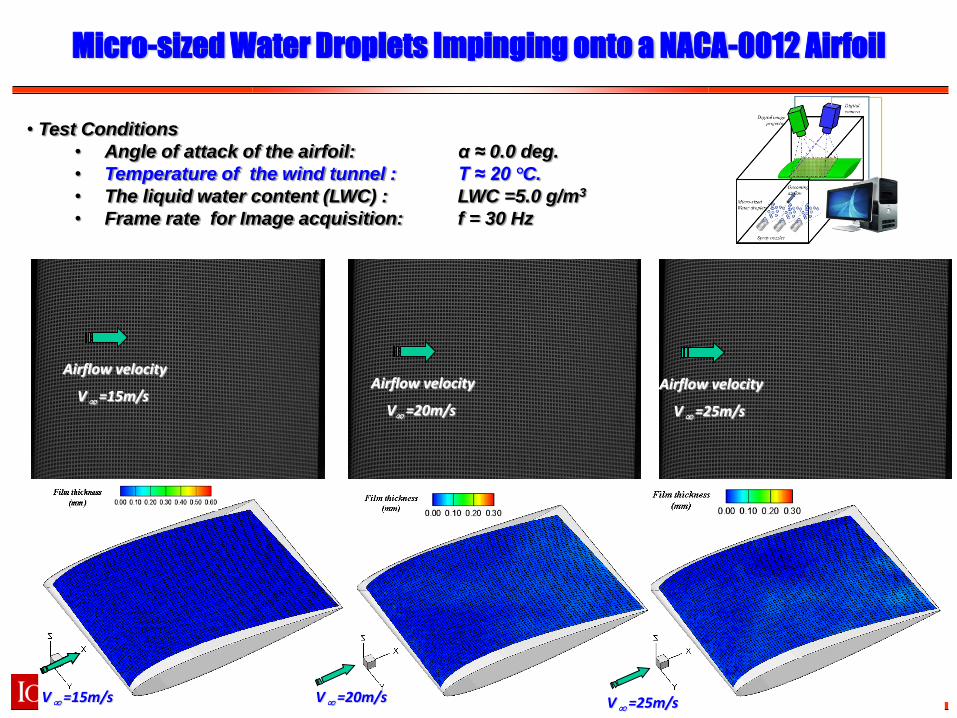
Micro-sized Water Droplets Impinging onto a NACA-0012 Airfoil
• Test Conditions
• Angle of attack of the airfoil: α ≈ 0.0 deg.
• Temperature of the wind tunnel : T ≈ 20 °C.
• The liquid water content (LWC) : LWC =5.0 g/m3
• Frame rate for Image acquisition: f = 30 Hz
Airflow velocity
V=20m/s Airflow velocity
V =15m/s Airflow velocity
V =20m/s
Airflow velocity
V =25m/s
V =15m/s V =20m/s V =25m/s

Copyright © by Dr. Hui Hu @ Iowa State University. All Rights Reserved!
Glaze Ice Accreting Process over a NACA0012 Airfoil
• Test Conditions • Oncoming airflow velocity : V ≈ 20 m/s • Angle of attack of the airfoil: α ≈ 5 deg. • Temperature of the wind tunnel : T ≈ -8 °C. • The liquid water content (LWC) : LWC =3.0 g/m3
• Total recording time : t = 110 seconds
Frame rate for Image acquisition, f = 150Hz, 10X replay
Upper surface
Lower surface
V
Videos of ice accretion
α ≈ 5.0 deg.
(Waldman R. and Hu H., 2015, Journal of Aerocraft, submitted)

Copyright © by Dr. Hui Hu @ Iowa State University. All Rights Reserved!
Glaze Ice Accreting Process over a NACA0012 Airfoil
V∞= 40 m/s
V∞= 60 m/s
V∞= 20 m/s
• T ∞ = - 8.0 °C;
• = 5 °;
• LWC = 1.1 g/m3
(Waldman R. and Hu H., 2015, Journal of Aircraft )

Copyright © by Dr. Hui Hu @ Iowa State University. All Rights Reserved!
IR Thermometry to Quantify the Unsteady Heat Transfer
Process
Incoming
airflow
• Experimental Conditions: V∞= 35 m/s; T ∞ = - 8.0 °C; AoA= 5 °; LWC = 3.0 g/m3
B A D C E
B A D C E
• Experimental Conditions: V∞= 35 m/s; T ∞ = - 8.0 °C; AOA = 5 °; LWC = 0.30 g/m3
(Liu Y. and Hu H., 2015, AIAA Journal, submitted)
Rime ice accretion
Glaze ice accretion

Copyright © by Dr. Hui Hu @ Iowa State University. All Rights Reserved!
Hydrophilic, Hydrophobic and Superhydrophobic
a). drop on a smooth surface; b). Wenzel state; c). Cassie–Baxter state; d). combined state.
Measured θ = 67 [deg]
Measured θ = 170 [deg]
Measured θ = 104 [deg]
• Hydrophilic; < 90 o • Hydrophobic; 90 o < < 150 o • Superhydrophobic; > 150 o
Lotus leaves
Copyright © by Dr. Hui Hu @ Iowa State University. All Rights Reserved!
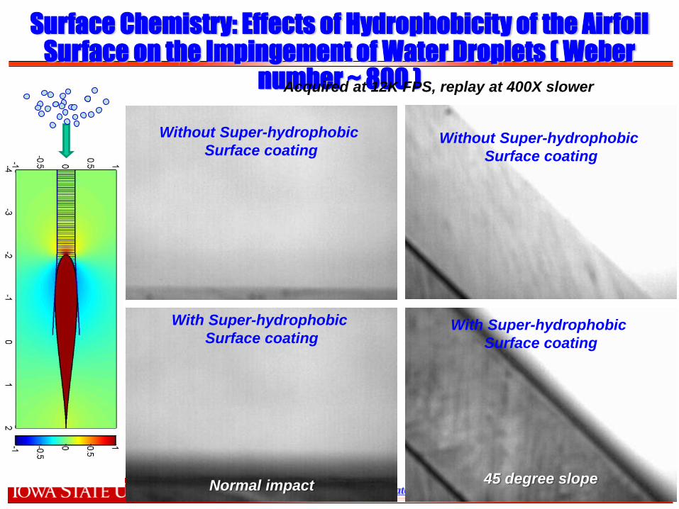
Surface Chemistry: Effects of Hydrophobicity of the Airfoil Surface on the Impingement of Water Droplets ( Weber
number ~ 800 )
45 degree slope
With Super-hydrophobic
Surface coating
Without Super-hydrophobic
Surface coating Without Super-hydrophobic
Surface coating
With Super-hydrophobic
Surface coating
Acquired at 12K FPS, replay at 400X slower
Normal impact

Copyright © by Dr. Hui Hu @ Iowa State University. All Rights Reserved!
Without Super-hydrophobic
Surface coating With Super-hydrophobic
Surface coating
Without Super-hydrophobic
Surface coating With Super-hydrophobic
Surface coating
Surface Chemistry: Effects of Hydrophobicity of the Airfoil Surface on the Impingement of Water Droplets
Copyright © by Dr. Hui Hu @ Iowa State University. All Rights Reserved!
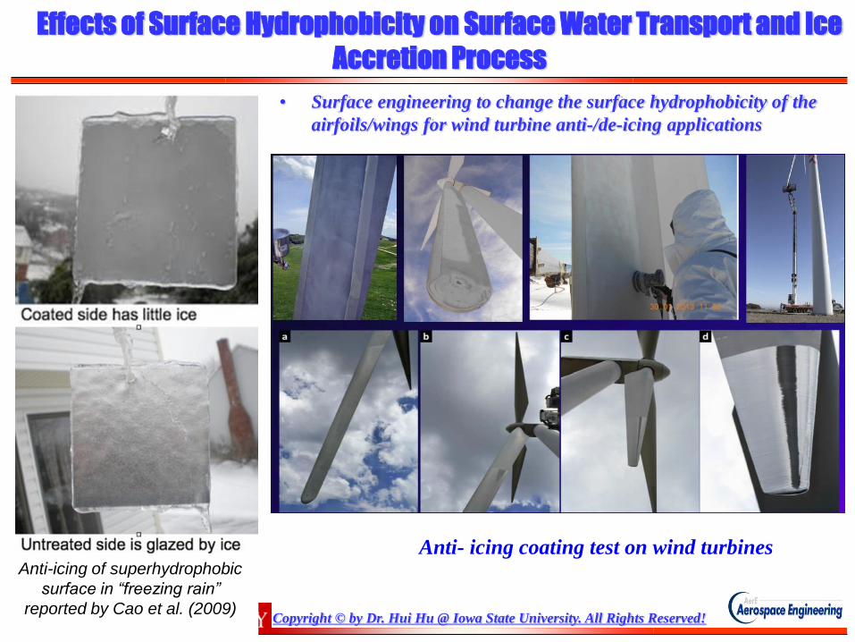
Effects of Surface Hydrophobicity on Surface Water Transport and Ice
Accretion Process
Anti-icing of superhydrophobic
surface in “freezing rain”
reported by Cao et al. (2009)
• Surface engineering to change the surface hydrophobicity of the
airfoils/wings for wind turbine anti-/de-icing applications
Anti- icing coating test on wind turbines

Copyright © by Dr. Hui Hu @ Iowa State University. All Rights Reserved!
Lab 13: Aerodynamic force measurement on an icing airfoil
Objective:
The objective of this lab is to measure the
aerodynamic forces acting on an airfoil in
a wind tunnel using a direct force
balance. The forces will be measured on
an airfoil before, during, and after the
accretion of ice to illustrate the effect of
icing on the performance of aerodynamic
bodies.
ISU Icing Research Tunnel velocity calibration
ISU Icing Research Tunnel schematic

Copyright © by Dr. Hui Hu @ Iowa State University. All Rights Reserved!
Lab 13: Aerodynamic force measurement on an icing airfoil
What you will be given for your
experiment:
• Icing wind tunnel
• A NACA 0012 airfoil model
• A force/torque transducer
• A data acquisition system
• A digital inclinometer
What your experiment needs to produce:
Lift, drag, and moment measurements vs
angle of attack (α = -2° – 20°) without icing.
Lift, drag, and moment measurements during
the icing process for α = 5°.
Lift, drag, and moment measurements vs
angle of attack (α = -2° – 20°) after the airfoil
has accumulated ice.
Force transducer–wing model configuration

Copyright © by Dr. Hui Hu @ Iowa State University. All Rights Reserved!
Lab 13: Aerodynamic force measurement on an icing airfoil
What results you will produce from the
experiment data:
•The lift, drag, and moment coefficients vs
angle of attack for the NACA 0012 airfoil with
uncertainty bounds for both the uniced and
iced conditions.
•Time history of the apparent lift, drag, and
moment coefficients during the icing process.
Beware!
•Lift and drag must be derived from the force
transducers local Normal and Tangential force
components:
e.g., L = FN * cos(α) - FT * sin(α)
•Coefficients are normalized by density, wind
speed and geometry:
CL= L / (½ ρ U2 s c)
CD= D / (½ ρ U2 s c)
CM= M / (½ ρ U2 s c2)
Force transducer–wing model configuration