lecture 15: biogas upgrading - valorgas ss 2013/valorgas_jyu_2013...(co2 + h2s) exhaust gas 0.5-2%...
TRANSCRIPT
UNIVERSITY OF JYVÄSKYLÄ
Lecture 15: Biogas upgrading
RE1 Biogas Technology for sustainable Second
Generation Biofuel Production
Prasad Kaparaju
23rd Jyväskylä Summer School August 12 - 16, 2013, Jyväskylä

UNIVERSITY OF JYVÄSKYLÄ
Content
Biogas utilization
Biogas composition
Biogas upgrading technologies

UNIVERSITY OF JYVÄSKYLÄ
BIOGAS UTILIZATION
Traditional
– Cooking, Lighting
Commercial
– Heat and steam
– Electricity and/or heat (cogeneration in CHP)
– Vehicle fuel
– Fuel cells
– Injection to natural gas grid

UNIVERSITY OF JYVÄSKYLÄ
Why to clean and upgrade biogas?
Meet the requirement of gas applications
– Removing trace compounds prevent mechanical wear &
corrosion
Improve the calorific value
– High methane content means high energy value fuel
Standardization of the gas
– Uniform gas/fuel quality for grid injection
– National standards for upgraded biogas fuel
– Standards by vehicle manufactures
Reduce harmful effects on environment
– Trace compounds removal
Biogas upgrading take 3-6% of biogas energy & costs € 10/GJ

UNIVERSITY OF JYVÄSKYLÄ
Definition
Biogas cleaning:
– Removal of water, H2S and other undesired trace
contaminants from the biogas like dust, Halogenated
compounds, siloxanes, ammonia, etc.
Biogas upgrading:
– Removal of CO2 to achieve gas quality for injection in gas grid
or vehicle fuel use
Biomethane:
– Upgraded biogas used for grid injection or vehicle fuel

UNIVERSITY OF JYVÄSKYLÄ
Biogas sources
Biogas is produced through biodegradation of various organic
materials (sugars, proteins and fats) under anaerobic conditions
There are different sources of biogas - feedstock/AD system
Feedstock AD system Produced gas
Sewage sludge Wastewater treatment plant Sewage gas
Agricultural wastes,
manures, energy crops,
crop residues etc.
Farm-scale biogas plants Biogas
Co-digestion of industrial
wastes with manures
Centralized-biogas plants Biogas
Municipal waste Landfills Landfill gas

UNIVERSITY OF JYVÄSKYLÄ
Biogas composition
The composition of biogas depends on several variables such as the type
of waste or the treatment process used to digest it.
Parameter Farm-scale
AD-plant
Centralised
AD-plant
Landfill Sewage
Treatment
plant
Natural
gas
(Holland)
CH4 (vol-%) 55-60 60-70 30-65 60-65 81-89
Other hydro carbons (vol-%) 0 0 0 0 3.5-9.4
H2 (vol-%) 0 0 0-3 0 -
CO2 (vol-%) 35-40 30-40 25-45 35-40 0.67-1
N2 (vol-%) <1-2 2-6 <1-17 <1-2 0.28-14
O2 (vol-%) <1 0.5-1.6 <1-3 <0.05-0.7 0
H2S (ppm) 25-30 0-2000 30-500 <0.5-6800 0-2.9
NH3 (ppm) ≈100 ≈100 ≈5 <1-7 0
Halogenated compounds
(as Cl-, mg/m
3)
<0.01 <0.25 0.3-225 0-2 -
Siloxanes (mg/m3) <0.03-<0.2 <0.08-<0.5 <0.3-36 <1-400 -
Wobbe index (MJ/m3) 24 – 33 24 – 33 20 - 25 25 - 30 44-55
Lower heating value (MJ/Nm3) 23 23 16 22 31-40

UNIVERSITY OF JYVÄSKYLÄ
Biogas collection from landfills
Gas collection wells
Gas pumping station
Courtesy: Dr Sormunen Kai

UNIVERSITY OF JYVÄSKYLÄ
Biogas treatment requirements
Application H2S CO2 H2O Siloxane
Cooking Yes No No No
Gas heater
(boiler)
< 1000
ppm
No No No
Stationary gas
engine (CHP)
< 500
ppm
No No condensation Yes
Vehicle fuel Yes Recommended Yes Yes
Natural gas grid
injection
Yes Yes Yes Yes
Hot fuel cells Yes No No condensation Yes
High pressure
compression
Yes Recommended Yes No
Removal of water, H2S and other possible contaminants required for all
commonly used gas applications

UNIVERSITY OF JYVÄSKYLÄ
Concept for biogas upgrading
Water vapor
Hydrogen sulphide
Oxygen
Ammonia
Nitrogen
Siloxanes
Dust
Particles
Methane
Carbon dioxide
Raw biogas
Bio
ga
s c
lea
nin
g
Bio
gas u
pgra
din
g
Biomethane

UNIVERSITY OF JYVÄSKYLÄ
Biogas cleaning
Dust and particles
Water
Sulphur compounds
Halogenated compounds
Ammonia
Oxygen and nitrogen
Siloxanes

UNIVERSITY OF JYVÄSKYLÄ
Water Condensate in the gas line
Contributes to corrosion
Lowers the efficiency of purification techniques
– active carbon adsorption
– silica gel treatment
Problem in cryogenic treatment due to ice formation
Technique Media Principle
Cooling
(approx. 2–5 °C)
Water condensation. The
gas is chilled below water
dew point
Adsorption Silica gel
Active carbon
Molecule sieve
The water binds to the solid
adsorbent (the dew point of
–20 °C is reached).
Reversible process
Absorption Glycol, Tri-ethylene-glycol
or hygroscopic salts
The water is absorbed into
a tri-ethylene-glycol solution

UNIVERSITY OF JYVÄSKYLÄ
Water removal
Adsorption
– Water vapour is adsorbed and reversely
bounded on the surface of adsorbents like
molecular sieves, silica gel or activated
carbon
– Adsorption and regeneration mode
(desorbed)
– Regeneration of adsorbent
• Heating to 200°C
• At atmp pressure – using air or vacuum
pump
• At high pressure – using minor amount of
dried, depressurised gas

UNIVERSITY OF JYVÄSKYLÄ
Sulphur compounds
Sulphides, disulphides & thiols
Raw biogas contain H2S 1000 -5000 ppm
On combustion, SO2 and SO3 are produced which reacts with
water to form H2SO4
– Causes severe corrosion of compressors, gas storage tanks
and engines
H2S limits for CHP is of 250 ppm
2 H2S + O2 → 2 S + 2 H2O
2 S + 2 H2O + 3 O2 → 2 H2SO4

UNIVERSITY OF JYVÄSKYLÄ
Sulphur deposits in gas engine
(Source: Duller 2005)
Damage caused by H2S Source: Applied Filter Technology

UNIVERSITY OF JYVÄSKYLÄ
Removal of Sulphur
Technique Principle
Oxygen/air dosing Biological oxidation Microbes oxidize
sulphur into elemental sulphur, sulphate
and sulphite
Chemical flocculation Flocculation by ferrous chloride, iron salts
or with lime
Adsorption Activated Carbon
Chemical Adsorption Sulphur reacts with KI, Fe(OH)3, (marsh
ore or limonite), ferrous oxide or with ZnO
Catalytic scrubber Chelate solution
Air/oxygen dosing
2H2S + O2 → 2 S + 2 H2O (Thiobacillus spp.)
Iron sponge (hydrated ferric oxide)
Fe2O3 · H2O + 3H2S → Fe2S3 + 4H2O
Ferric Chloride Injection
3H2S + 2FeCl3 → S + 2FeS + 6HCl
UNIVERSITY OF JYVÄSKYLÄ
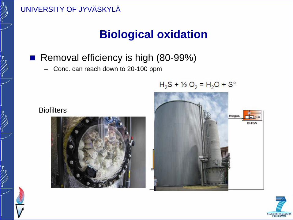
Biological oxidation
Removal efficiency is high (80-99%) – Conc. can reach down to 20-100 ppm
Biofilters

UNIVERSITY OF JYVÄSKYLÄ
Siloxanes
Volatile silicones compounds bonded by organic radicals
R – Si – O – Si – R
Common in landfill and sewage gas only (D4 and D5)
Absent in natural gas or biogas from agricultural biogas plants.
Main source is consumer products
Oxidised to SiO2 during combustion
Deposits on valves, cylinder walls and liners → cause extensive
damage by erosion or blockage
Octamethylcyclotetrasiloxane (D4) Decamethylcyclopentasiloxane (D5)
Si
R
O
R

UNIVERSITY OF JYVÄSKYLÄ
Siloxane and silicate depositions
Silicate layers on a catalytic after-
burner Source: Pierce (2005)
Gold-coloured siloxane layer on
the inner surfaces of a cylinder
Source: Environmental Agency
(2002)

UNIVERSITY OF JYVÄSKYLÄ
SiO2 depositions on boiler tubes and damage to an engine
piston
Source: Applied Filter Technology.

UNIVERSITY OF JYVÄSKYLÄ
SILOXANE REMOVAL
Adsorption with activated carbon
– Regeneration of activated carbon is not possible
– Biogas has to be heated before the treatment to prevent water
saturation of activated carbon
– At 24 bars and 4.4 °C – 10 to 15 g siloxanes/kg activated
carbon
Adsorption with silica gel or activated aluminium
Absorption in a liquid medium (organic solvents)
– Counter flow columns with or without regeneration of the
scrubbing liquid
Cooling (-23 °C)
– Most of the silicon components are removed at low temp.

UNIVERSITY OF JYVÄSKYLÄ
Overview biogas upgrading technologies
(for CO2 - removal)
Adsorption Absorption Permeation Cryogenic
Pressure swing
adsorption
(PSA)
Water scrubber
Physical
absorption
(organic
solvents)
Chemical
absorption
(organic solvents)
Low/High pressure
membrane
separation
Cryogenic separation
UNIVERSITY OF JYVÄSKYLÄ
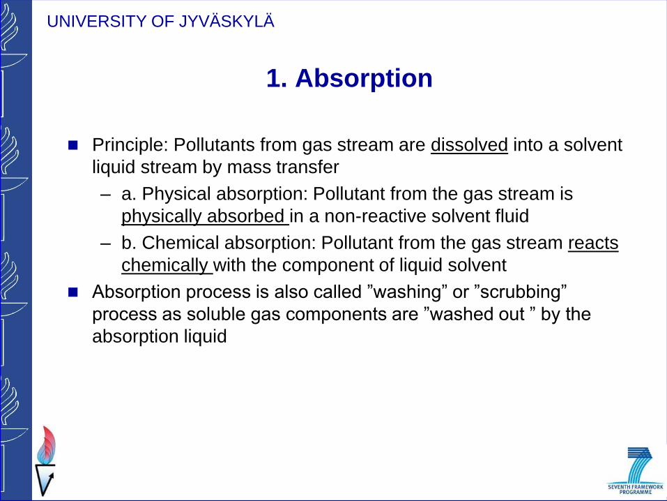
1. Absorption
Principle: Pollutants from gas stream are dissolved into a solvent
liquid stream by mass transfer
– a. Physical absorption: Pollutant from the gas stream is
physically absorbed in a non-reactive solvent fluid
– b. Chemical absorption: Pollutant from the gas stream reacts
chemically with the component of liquid solvent
Absorption process is also called ”washing” or ”scrubbing”
process as soluble gas components are ”washed out ” by the
absorption liquid

UNIVERSITY OF JYVÄSKYLÄ
a. Physical absorption
CO2 is removed based on the difference in solubilities of the
gaseous components of biogas in an absorption liquid.
Solubility of CO2 is 55 times higher than CH4
H2S > > CO2 > CH4
Solubility increases with increase in pressure and decrease in
temperature
Solubility of CO₂ and CH₄ at 1 atmosphere (101.325 kPa) and
temperature

UNIVERSITY OF JYVÄSKYLÄ
Solubility of CO2 in water
The solubility of CO₂ in water decreases with increase in temp
and increases with increase in pressure
Temp (°C)
Pressure
(bar)
0 10 20 30
1 0.4 0.25 0.15 0.10
20 3.15 2.15 1.30 0.90
50 7.70 6.95 6.0 4.80

UNIVERSITY OF JYVÄSKYLÄ
1. Water scrubbing
Most common biogas upgrading
technology
Principle: CO2 & H2S are more soluble in
water than CH4
Other trace compounds viz., NH3, SO2,
halogenated compounds etc can also be
removed.
Water scrubbing
– with regeneration of wash water
– Without regeneration of wash water
(single pass)

UNIVERSITY OF JYVÄSKYLÄ
1. Water scrubbing technology
(regeneration of wash water)
50-70%
CH4
2 bars
H2O
condensation
8-10 bars
Double
compressor 5-10C
2-4 bar
Water
regeneration
(CO2 + H2S)
Exhaust gas
0.5-2% CH4
13 bars
H2O
>96% CH4
(Courtesy: ISET, 2008)

UNIVERSITY OF JYVÄSKYLÄ
Different absorption designs
Counter-current Co‐current flow Tower

UNIVERSITY OF JYVÄSKYLÄ
Other absorption liquids
Polyethylene glycol (PEG)
Upgrading principle is similar to water scrubbing process with
regeneration of the wash water
Main difference is that CO2 and H2S are more soluble in PEG
than in water
– Lower solvent demand
– Reduced pumping (circulation of PEG)
Water and hydrocarbons are also absorbed in PEG
– Biomethane is low water content and does not need drying
Selexol™ is trade name for dimethylester of PEG
H2S removal beforehand is recommended
93-98% CH4 in product gas

UNIVERSITY OF JYVÄSKYLÄ
Physical absorption using organic solvent
50-70%
CH4
6-7 bars 10-20 C
40-80 C
Exhaust gas
1-4% CH4
>96% CH4
(Courtesy: ISET, 2008)

UNIVERSITY OF JYVÄSKYLÄ
b. Chemical absorption
Chemicals:
– Alkanol amines : mono ethanol amine (MEA) or di‐methyl
ethanol amine (DMEA)
– Potassium carbonate solutions
Gas components do not simply dissolve in the solvent but react
chemically
CO2, H2S absorbed (H2S removal is required)
N2 cannot be absorbed
Highly selective reaction between amine & CO2
More CO2 per unit volume is absorbed than WS system
– smaller volumes and plant sizes
Operated at very low partial pressure
Chemical is regenerated by heat and/or vacuum

UNIVERSITY OF JYVÄSKYLÄ
Chemical scrubbing
CO2 absorption using aqueous amino acid salt solutions:
106-160 C
99% CH4
1 bar
4 bar
(Courtesy: ISET, 2008)
UNIVERSITY OF JYVÄSKYLÄ
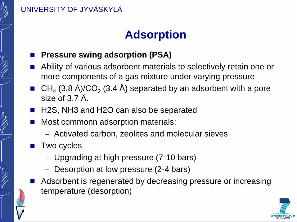
Adsorption
Pressure swing adsorption (PSA)
Ability of various adsorbent materials to selectively retain one or
more components of a gas mixture under varying pressure
CH4 (3.8 Å)/CO2 (3.4 Å) separated by an adsorbent with a pore
size of 3.7 Å.
H2S, NH3 and H2O can also be separated
Most commonn adsorption materials:
– Activated carbon, zeolites and molecular sieves
Two cycles
– Upgrading at high pressure (7-10 bars)
– Desorption at low pressure (2-4 bars)
Adsorbent is regenerated by decreasing pressure or increasing
temperature (desorption)

UNIVERSITY OF JYVÄSKYLÄ
Pressure-swing adsorption
4-7 bar
(Courtesy: ISET, 2008)

UNIVERSITY OF JYVÄSKYLÄ
(Courtesy: ISET, 2008)

UNIVERSITY OF JYVÄSKYLÄ
PSA with activated carbon

UNIVERSITY OF JYVÄSKYLÄ
Membrane technology
Different molecules in a gas mixture have different permeation rate
through a given permeable membranes
Important parameter: permeability ratio = selectivity
Permeation rate is dependent on the gas ability to dissolve in and
diffuse through the membrane
Driving force for the flux of each component is the difference in
partial pressure over the membrane
For good separation – high permeability between the components

UNIVERSITY OF JYVÄSKYLÄ
Membrane technology
Membranes
– Usually constructed as hallow fibre modules for large surface
area
– Several modules are used for specific gas separation
– Polymers used as solid membranes
– Acetate-cellulose membrane: Permeability of H2S is 60 times
and CO2 is 20 times than CH4
Membrane separation
– High pressure (25-40 bars)
– Low pressure (9 bars)

UNIVERSITY OF JYVÄSKYLÄ
Two-stage membrane system
25-40
bar
Courtesy: Biogas Upgrading Plant in Bruck/Leitha (Austria)

UNIVERSITY OF JYVÄSKYLÄ
Membrane technology
Courtesy: Biogas Upgrading Plant in Bruck/Leitha (Austria)

UNIVERSITY OF JYVÄSKYLÄ
Cryogenic separation
Each contaminant have different boiling points and thus liquefies
at a different temperature-pressure domain
– CO2 ‐78 °C and CH4 ‐160 °C
The raw biogas is cooled down to the temperatures where the
CO2 in the gas condenses or sublimates (194.5 K) and can be
separated as a liquid or a solid fraction

UNIVERSITY OF JYVÄSKYLÄ
Cryogenic process
Raw gas is compressed in multi stage with intercooling using chillers
and heat exchangers
CH4 accumulates in the gas phase
CO2 is further processed for enrichment
Distillation
column
Biogas
25 °C
1 bar
37% CH4
58% CO2
5% other
Product gas
91% CH4
8% N2
1% other Waste
stream
1 bar
0.6% CH4
98% CO2
Cooler Cooler Cooler Compressor Compressor
- 70
°C
1 bar
207 °C
21 bar
- 10
°C
21 bar
54 °C
40 bar
-10 °C
40 bar
Recirculation of product stream as cooling agent

UNIVERSITY OF JYVÄSKYLÄ
Off-gas CH4 treatment
Off-gas seldom contains high concentrations to maintain a flame without adding
natural gas or biogas
Methane loses should be kept as low as possible
– Loss of energy
– GHG emissions
CH4 can be present
– In the off‐gas leaving a PSA‐column
– In air from a water scrubber with water circulation
– In water in a water scrubber with water recirculation
Offgas treatment depends on process integration:
– Mixing with biogas and utilisation in CHP plants
– Thermal oxidation (flameless oxidation systems or direct combustion of low-
cal gas)
– Catalytic oxidation
– Further treatment using additional membrane separation stage

UNIVERSITY OF JYVÄSKYLÄ Comparison of biogas upgrading technologies
Water scrubbing
Chemical (amine)
scrubbing
PSA Membrane Cryogenic
Working pressure
( bars )
7 - 10
Atmp
4 – 7
8 - 10
25- 40
Maximum achievable
yield (%)
94
90
91
98
98
Maximum achievable
purity (%)
98
98
98
89.5
91
CH4-losses <2 <0.1 <2 – <2-10
Produced gas dryer
required Yes - Yes - No + No + No +
H2S pre treatment
required No + Yes - Yes - Yes - Yes -
Waste gas treatment
required No + Yes - No + No +
Yes -
Technical availability
per year (%)
96
91
94
98
98
Energy requirement
(kWh/m3 of upgraded
biogas)
0.43
0.646
0.335
0.769
–
Investment cost (€/yr) 265,000 353,000a -869,000d 680,000 233,000a -749,000b 908,500
Maintenance cost
(€/yr)
110,000
134,000a -179,500b
187,250
81,750a-126,000b
397,500
Cost price per Nm3
biogas upgraded
(euros)
0.13 0.17a -0.28b
0.25 0.12a-0.22b
0.44
References 32 9 33 4 1
Source: de Hullu et al. 2008; Berndt, 2006; Beil, 2009; Patterson et al., 2009

UNIVERSITY OF JYVÄSKYLÄ
Uses of biomethane

UNIVERSITY OF JYVÄSKYLÄ
Biogas as vehicle fuel
Biomethane can be used in vehicles operated with natural gas
without any engine modification.
Bifuel vehicles use gas and gasoline
– Range with gas 200‐400 km
Dual fuel vehicles use methane and diesel
Biomethane is compressed to 200 bars for on-site storage or
transport by road.
It is also distributed through natural gas grid or separate on-site
fuelling stations

UNIVERSITY OF JYVÄSKYLÄ
Biogas as vehicle fuel

UNIVERSITY OF JYVÄSKYLÄ
Biogas injection to natural gas grid
Biogas can be distributed via natural gas grid
Biogas plants usually locates in rural areas → grid connects the
production site with more densely populated areas
– New customers
– Improves the local security of supply
Some countries have standards for gas injection to grid
– Methane, carbon dioxide, sulphur compounds, moisture,
Wobbe index, siloxanes…
– Low‐ and High value gas
In most cases biogas needs to be upgraded before gas grid
injection
– Wobbe index

UNIVERSITY OF JYVÄSKYLÄ
EU natural gas grid

UNIVERSITY OF JYVÄSKYLÄ Biomethane standards for grid injection or vehicle fuel use Compound France1 Germany2 Sweden3 Switzerland4 Austria5 Holland6
L gas H gas L gas H gas Limited
injection
Unlimited
injection
Lower Wobbe
Index (MJ/Nm3)
43.9-47.3
Higher Wobbe
Index (MJ/Nm3)
42.48-
46.8
48.24-
56.52
37.8-46.8 46.1-56.5 47.7-56.5 43.46-
44.41
CH4 (vol-%) 97 >50 >96 >80
CO2 (vol-%) <2 <6 <6 <26
O2 (vol-%) <0.01 <3 <1 <0.5 <0.56
H2 (vol-%) <6 <5 <5 <46 <12
CO2+O2+N2 (vol-
%)
<5
Water dew point
(°C)
<-5 (at MOP
downstream from
injection point
<t4 <t4-5 <-87 -108
Relative humidity
(%)
0.55-0.75 <60%
Total S (mg/Nm3) <100 (instant content)
<75 (Annual average)
<30 <23 <30 <5 <45
MON (Motor
octane number)
>130
NH3 (mg/Nm3) <20
H2S (mg/Nm3) <30
1National guidance no. 2004-555 (2004) and technical specifications (2006); 2Standards DVGW G260 and G262; 3Standard SS155468; 4Directive SSIGE G13; 5Directive OVGW G31 and G33; 6Proposition for Dutch gas suppliers
Adapted after IEA Bioenergy, (2009).

UNIVERSITY OF JYVÄSKYLÄ
Upgrading Technology Advantages Disadvantages
Chemical absorption 1. Almost complete H2S removal
2. Cost effective on larger scale
3. Good energy efficiency & operating costs
1. Safety – solvent is dangerous to handle
2. Risk of pollution by chemical contamination
3. Uneconomic capital and energy costs for gas
streams with high CO2 loadings (>20%)
4. Does not remove inerts (e.g. O2 and N2)
5.Only removal of one component in column
6. Expensive catalyst
High pressure water
scrubbing
1. Removal gases and particulate matter
2. High purity, good yield
3. No special chemicals or equipment required
4. Neutralization of corrosive gases
5. Excellent safety; proven performance
6. Reliable, simple and easy to maintain
7. Low capital and operating cost
8. Siloxanes effectively removed
1.Limitation of H2S absorption due to changing pH
2.H2S damages equipment
3.Requires a lot of water, even with the regeneration
process
4. Practical capacity limit ≈ 2200 Nm3/h per unit
5. Does not remove inerts (e.g. O2 and N2)
Pressure swing adsorption 1. More than 97% CH4 enrichment
2. Low power demand
3. Low level of emissions
4. Adsorption of N2 and O2
5. Can remove some inert gases, but sometimes requires
an additional process module
6. Cost effective on small scale
1. Media becomes poisoned and needs replacement
2. Process difficult to control – problems maintaining
high CH4 recovery
3. Upstream H2S removal required step needed
Membrane process 1. Simple & compact plant
2. Low capital cost
3. Low maintenance
4. Low energy requirements
5. Easy process
1. Relatively low CH4 yield (92% max.)
2. H2S removal step needed
3. Membranes can be expensive
4. High energy consumption
5. Membranes foul and require replacement
6. Does not remove inerts (e.g. O2 and N2)
Cryogenic separation 1.Can produce large quantities with high purity
2. Can produce LNG
3. Cost effective on very large scale
4. Easy scaling up
5. No chemicals used in the process
1. Complex plant, high capital and operating costs
2. Operational problems due to solid CO2 formation on
heat exchangers.
3. Very low temperatures and high pressures create
potentially hazardous plants
4. A lot of equipment is required
Source: de Hullu et al. 2008; Berndt, 2006; Beil, 2009; Patterson et al., 2009

UNIVERSITY OF JYVÄSKYLÄ
Definition
Wobbe index (WI): Actual heating value of natural gas arriving,
from the gas line, at the orifice where a burner is located.
Relative density: The ratio of the density of gas to air at STP
Higher heating value (HHV): Energy released when one normal
cubic meter (Nm3) of biogas is combusted and the water vapour
formed in the combustion is condensed.
Lower heating value (LHV): Energy formed when the water
vapour is still not condensed.
Examples : biogas (60 % CH4): 21.5 MJ/Nm3 & pure CH4: 35.8
MJ/Nm3.

UNIVERSITY OF JYVÄSKYLÄ
Biogas upgrading technologies
Separation of CH4 and CO2 of the pre-cleaned biogas in order to
obtain the calorific value, Wobbe index and relative density
required for the final use
If gas is injected to gas grid – gas is compressed and dried to
condensation point of the ground temperature at the actual
pressure
If gas is injected into a low pressure pipe of the natural gas grid –
small amounts of sulphurous compounds (mercaptans &
tetrahydrotiophen) are added (odourization)