lecture 2 fundamentals of electrical engineering
TRANSCRIPT

Lecture 2Fundamentals of Electrical
Engineering

Class Website
• Course website: http://www.soe.ucsc.edu/classes/ee070/Fall07/
• Login name: ee070s
• Password: towan58

Introduction1. Define current, voltage, and power, including their units.
2. Calculate power and energy, as well as determine whether energy is supplied or absorbed by a circuit element.
3. State and apply basic circuit laws.
4. Solve for currents, voltages, and powers in simple circuits.

Electrical Current
Electrical current is the time rate of flow of electrical charge through a conductor or circuit element. The units are amperes (A), which are equivalent to coulombs per second (C/s).

Electrical Current
t
t
tqdttitq
dt
tdqti
0
)()()(
)()(
0

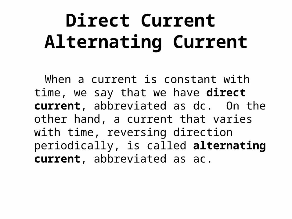
Direct Current Alternating Current
When a current is constant with time, we say that we have direct current, abbreviated as dc. On the other hand, a current that varies with time, reversing direction periodically, is called alternating current, abbreviated as ac.

.


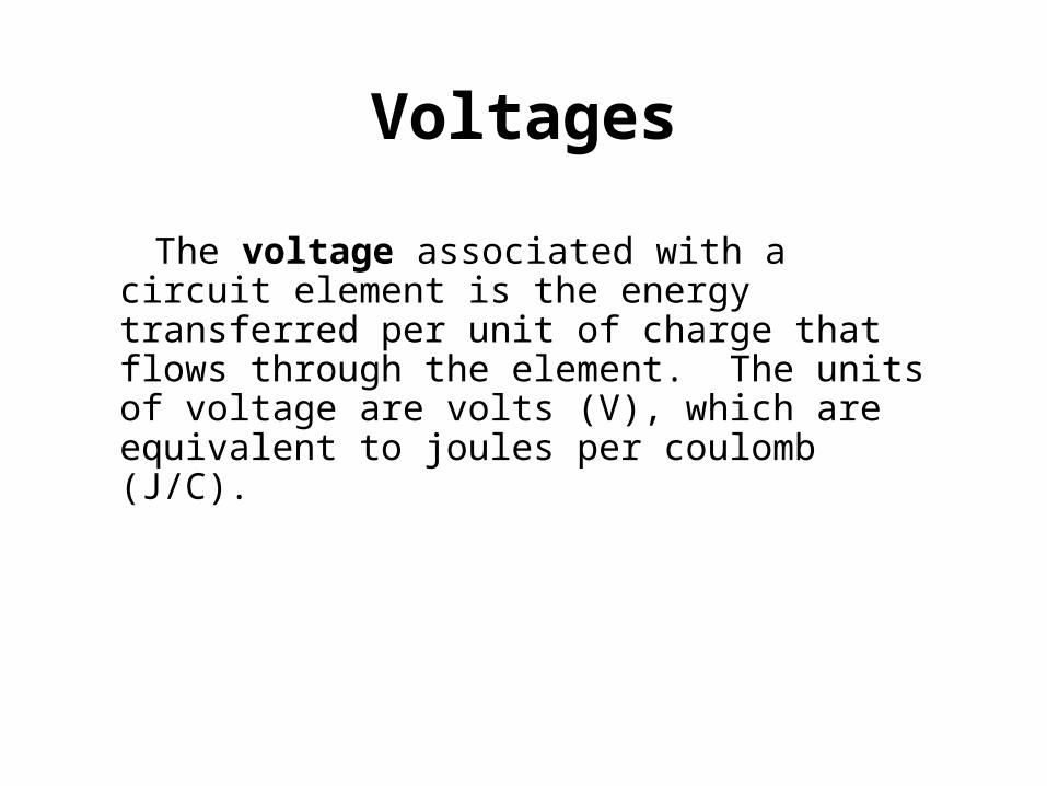
Voltages
The voltage associated with a circuit element is the energy transferred per unit of charge that flows through the element. The units of voltage are volts (V), which are equivalent to joules per coulomb (J/C).
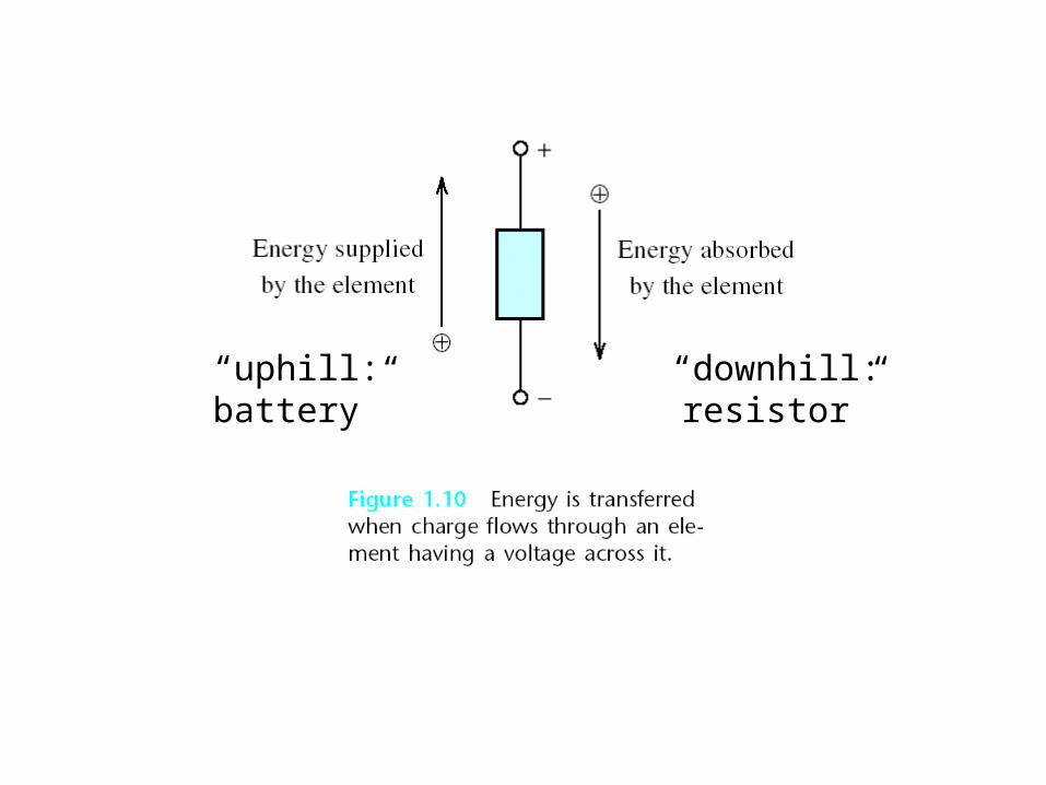
“downhill: resistor”“uphill: battery”


POWER AND ENERGY
2
1
)(
)()()(t
t
dttpw
titvtp Watts
Joules

If the current flows opposite to the passive configuration, the power is given by p = -vi
Current is flowing in the passive
configuration

Pa = iava = (2A)*(12V) = 24W, energy is being absorbed
Pb = -ibvb = -(1A)*(12V) = -12W, energy is being supplied
Pc = icvc = (-3A)*(12V) = -36W, energy is being supplied

Power and Energy
v(t) = 12 V
i(t) = 2e-t A
p(t) = v(t)i(t) = 24e-t
Jeedtedttpw t 24)24(2424)(0 0
0


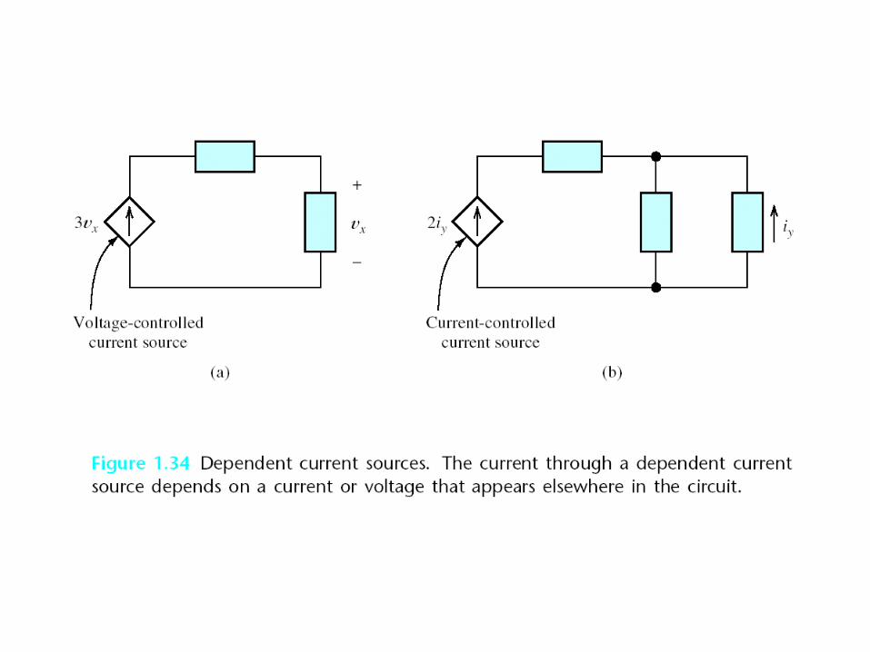
• An ideal voltage source has a voltage vx =12 V independent of the load
• An ideal conductor requires that vx = 0
?


Resistors and Ohm’s Law
Riv
iRv
abab
a
b
The units of resistance are Volts/Amp which are called “ohms”. The symbol for ohms is omega:

George Simon Ohm, 1789-1854
In 1805 Ohm entered the University of Erlangen but he became rather carried away with student life. Rather than concentrate on his studies he spent much time dancing, ice skating and playing billiards.
http://www-groups.dcs.st-and.ac.uk/~history/Mathematicians/Ohm.html
R
VI

Conductance
GviR
G
1
The units of conductance are 1/ or -1. The units are called “siemens”

Resistance Related to Physical Parameters
A
LR
is the resistivity of the material used to fabricate the resistor. The units of resitivity are ohm-
meters (-m)

Power dissipation in a resistor
R
vRivip
22

KIRCHHOFF’S CURRENT LAW
• The net current entering a node is zero.
• Alternatively, the sum of the currents entering a node equals the sum of the currents leaving a node.

Gustav Kirchhoff (1824-1887)
The principle of conservation of electric charge implies that:
At any point in an electrical circuit where charge density is not changing in time, the sum of currents flowing towards that point is equal to the sum of currents flowing away from that point.
A charge density changing in time would mean the accumulation of a net positive or negative charge, which typically cannot happen to any significant degree because of the strength of electrostatic forces: the charge buildup would cause repulsive forces to disperse the charges.
Kirchhoff's Current Law
http://www-groups.dcs.st-and.ac.uk/~history/Mathematicians/Kirchhoff.html


(a) Currents into the node = 1A+3A = 4A current out of the node ia
(b) Currents into the node = 3A+1A+ib = current out of the node = 2A so ib=2A-4A=-2A
(c) Currents into the node = 1A+ic+3A+4A = current out of the node= 0 amps so ic =-8A

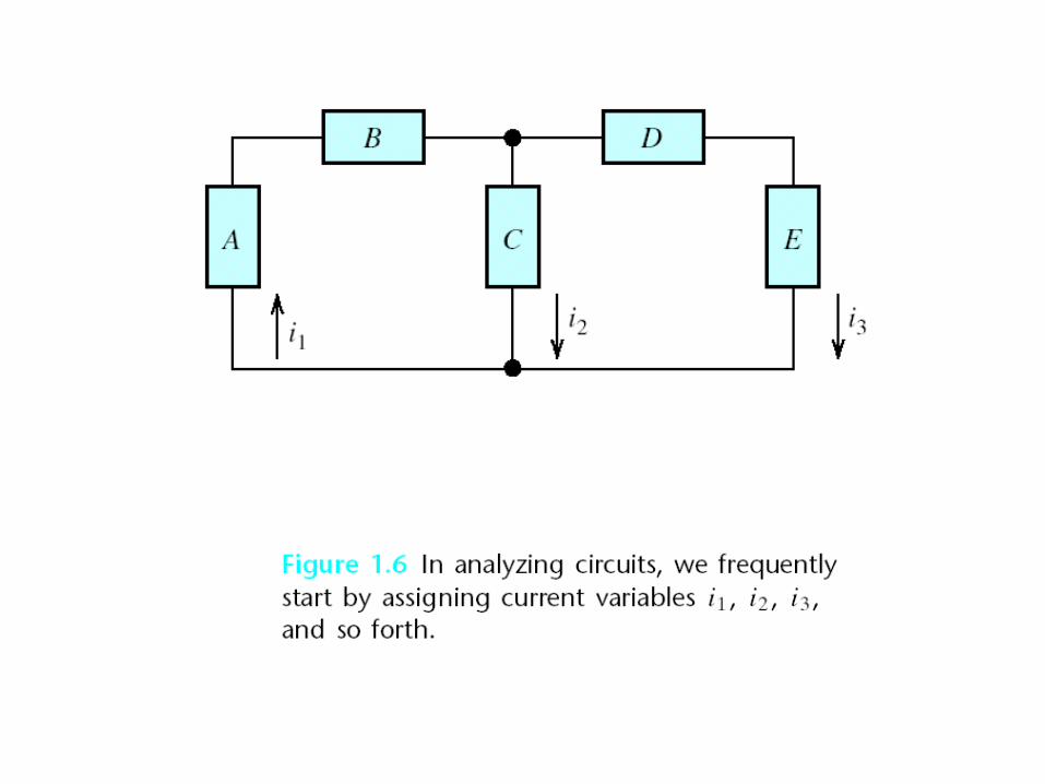
Which elements are in series?

KIRCHHOFF’S VOLTAGE LAW
The algebraic sum of the voltages equals zero for any closed path (loop) in an electrical circuit.

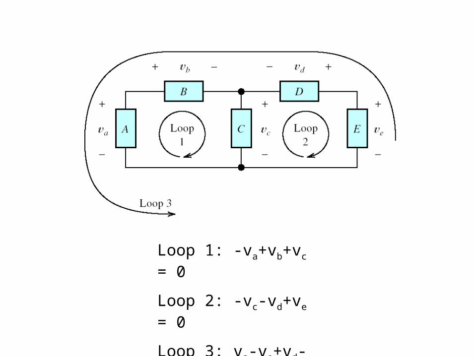
Loop 1: -va+vb+vc = 0
Loop 2: -vc-vd+ve = 0
Loop 3: va-ve+vd-vb = 0


KVL through A and B: -va+vb = 0 va = vb
KVL through A and C: -va - vc = 0 va = -vc

-3V - 5V + vc = 0 vc = 8V
-8V - (-10V) + ve = 0 ve = -2V
Which elements are in series? Which elements are in parallel?

Find the current, voltage and power for each element:
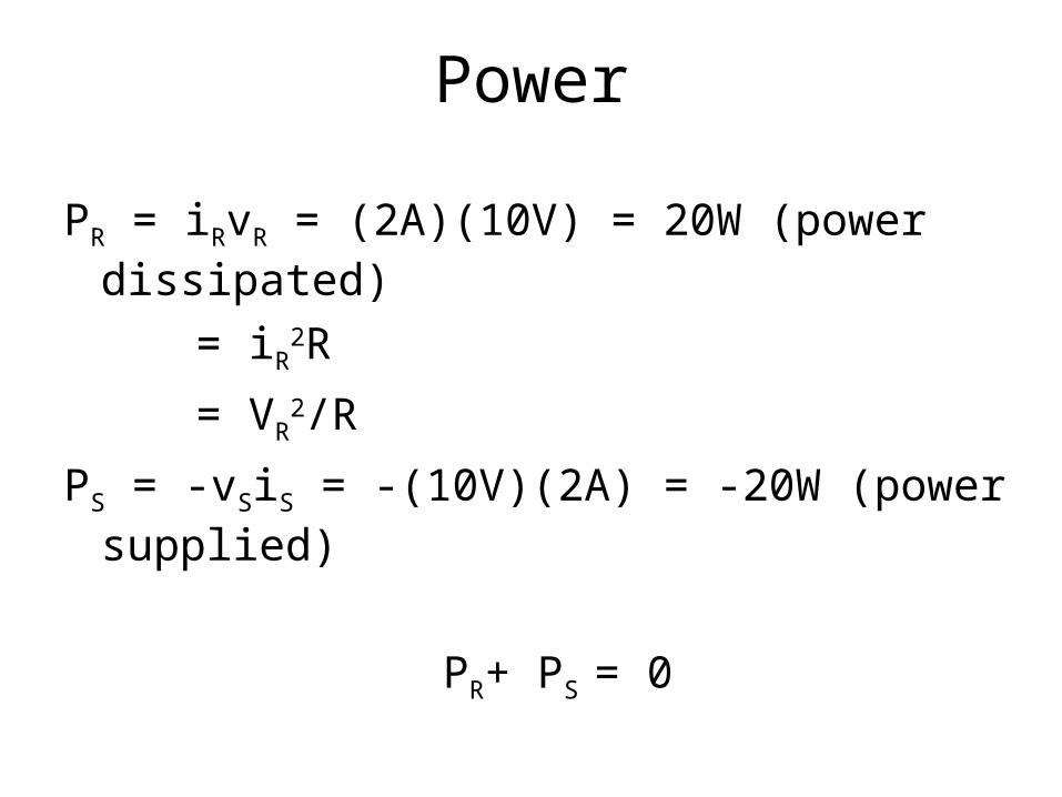
Power
PR = iRvR = (2A)(10V) = 20W (power dissipated)
= iR2R
= VR2/R
PS = -vSiS = -(10V)(2A) = -20W (power supplied)
PR+ PS = 0
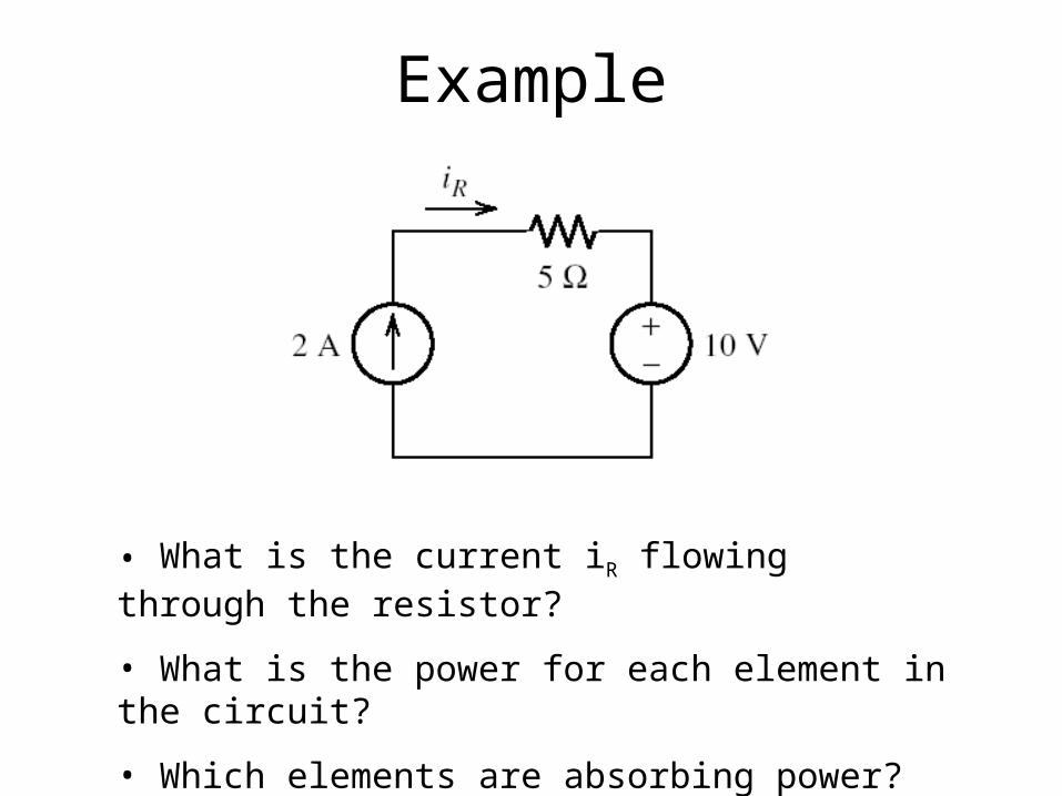
• What is the current iR flowing through the resistor?
• What is the power for each element in the circuit?
• Which elements are absorbing power?
Example

• Since all of the elements are in series, the same current iR= 2A runs through each of them
• The voltage drop across the resistor:
vR= iR = (2A)(5) = 10V• Apply KVL:
vc = vR + 10 = 20V• The power dissipated in each element:
pR = iR2R = (2A)2(5) = 20W (absorbing)
pvs= iv = (2A)(10V) = 20W (absorbing)
pcs= -iv = -(2A)(20V) = 40W (supplying)

Use Ohm’s law, KVL and KCL to find Vx
Example

Ohm’s Law:
VR4 = (1A)(5) = 5V = VR2 = VR3
IR2 = 5V/10 = 0.5A
IR3 = 5V/5 = 1A
KCL: IT = IR2 + IR3 + IR4 = 0.5A + 1A + 1A = 2.5A
Ohm’s Law: VR1= ITR1 = (2.5A)(5) = 12.5V
KVL: Vx = VR1 + VR4 = 12.5V+5V = 17.5V
R3R2
R1
R4