lecture 20 -...
TRANSCRIPT

Lecture – 20

SECTION – C
Local Area Network

Two Categories of N/Ws
Point to Point Connections: All stations
share a single communication channel
Broadcast N/Ws: Pairs
of hosts (or routers) are directly connected
Broadcast Network Point-to-Point Network
In Broadcast n/w, key Issue is
HOW TO DETERMINE WHO GETS
TO USE THE CHANNEL, WHEN
THERE IS COMPETETION FOR
IT…

Example
Consider a Conference Call, in which 6 people
on 6 different telephones are all connected
together so that each one can hear & talk to all
others. Its like when one of them stops
speaking, 2 or more will start talking at once…
Leading to chaos…..
Solution: Some sort of communication channel
should be followed to avoid network congestion
Problem comes:
When only a single channel is available….
determining who should go next is much
harder. Many protocols are designed to
solve this Issue.
Broadcast channels are sometimes called
multi-access channels or random
access channels.

MAC Sublayer
The protocols used to determine who goes next on a
multi-access channel belong to sub layer of the data-
link layer called the MAC (Medium Access Control) sub
layer.
Its especially important in LANs & almost all of which
use a multi-access channel as the basis of their
communication.
WANs uses a point to point links, except for
satellite networks.
The Channel Allocation Problem
How to allocate a single broadcast
channel among competing users?
Two ways are there:-
Static channel allocation in LANs &
MANs.
Dynamic channel allocation in
LANs & MANs.
Static Channel Allocation
Traditional way of allocating a single channel like
telephone trunk among multiple users is Frequency
Division Multiplexing (FDM).
If there are N users, the bandwidth is divided in to N equal
sized portions, each user being assigned one portion. Since
each user has a private frequency band, there is no
interference b/t users.
When there is a small & fixed number of users, each of which
has a heavy (buffered) load of traffic.
FDM is a simple & efficient mechanism.

Static Channel Allocation cont...
Problem with FDM
When some users are quiescent (inactive) their bandwidth is simply lost. They are not using it & no one else is allowed to use it either.
As a result most of the channels will be idle most of the time.
Problem with Time Division multiplexing (TDM)
In TDM, each user is statically allocated
every Nth time slot. If a user does not use
the allocated slot, it just lies fallow
(empty).
Since none of the traditional static channel
allocation methods works well with bursty
traffic,
Lets explore dynamic methods…

Dynamic Channel Allocation
Five assumptions are there in terms of solving channel
allocation problem:
1. Station Model.
2. Single Channel Assumption.
3. Collision Assumption.
4. Two parts are there
(a) Continuous time
(b) Slotted Time
5. Two distinctions made
(a) Carrier Sense.
(b) No Carrier Sense.
Dynamic Channel Allocation cont..
Assumption 1: Station Model
The model consists of N independent
stations (computers, telephones etc) each
with a user/program that generates frames
for transmission.
Once a frame has been generated, the
station is blocked & does nothing until the
frame has been successfully transmitted.

Dynamic Channel Allocation cont..
2. Single Channel Assumption
A single channel is available for all
communication.
All stations can transmit on it, & all
can receive from it.
In case of Hardware: all stations are
equivalent, Protocol software may
assign priorities to them.

Dynamic Channel Allocation cont..
3. Collision Assumption
If two frames are transmitted simultaneously,
they overlap in time & the resulting signal is
garbled (corrupted), this event is called
Collision.
All stations can detect collisions.
A collided frame must be transmitted again
later.
There are no errors other than those generated
by Collisions.

Dynamic Channel Allocation cont...
Assumption: 4
4a. Continuous time: Frame transmission can begin at any instant. There is no
master clock dividing time into discrete intervals.
4b. Slotted time: Time is divided into discrete intervals (slots). Frame
transmission always begin at the start of a slot. A slot
may contain 0,1 or more frames, corresponding to an
idle slot, a successful transmission, or a collision
respectively.

Dynamic Channel Allocation cont...
Assumption: 5
5a. Carrier Sense: Stations can tell if the channel is in use before trying to
use it. If the channel is sensed as busy, no station will
attempt to use it until it goes idle.
5b. No Carrier Sense Stations cannot sense the channel before trying to use
it. They just go ahead & transmit. Only later can they
determine whether or not the transmission was
successful.

Lecture – 21

MAC Protocols cont...
Multiple Access Protocols
Many algorithms for allocating a multiple access channels are known.
ALOHA
• Pure ALOHA
• Slotted ALOHA
Carrier Sense Multiple Access Protocols (CSMA)
• Persistent & Non-persistent CSMA
• CSMA with Collision detection.
Collision free Protocols
• A Bit Map Protocol
• Binary Countdown.
MAC Protocols cont...
ALOHA (Abramson's Logic of Hiring Access )
The basic idea is applicable to any system in which
uncoordinated users are competing for the use of single
shared channel.
Two versions: Pure & Slotted.
Differences
• They differ w.r.t. whether or not time is divided up into
discrete slots into which frames must fit.
• Pure ALOHA does not require global time
synchronization; slotted ALOHA does.

ALOHA cont…
The basic idea is simple: let users transmit whenever they
have data to be sent.
There will be collisions, of course, and colliding frames will
be destroyed.
Due to Feedback Property of broadcasting A sender
can always find out whether or not its frames was
destroyed by listening to the channel.
If the frame was destroyed, the sender just waits for some
time & sends it again.
Systems in which multiple users share a common channel in
a way that can lead to conflicts are widely known as
contention systems.

Pure ALOHA
In this case, we’ve made the frames all the same length
because the throughput of ALOHA systems is
maximized by having a uniform size rather than allowing
variable length frames.
Whenever two frames try to occupy the channel at the
same time, there will be a collision & both will be
garbled.
If the first bit of a new frame overlaps with just the last
bit of a frame almost finished, both frames will be totally
destroyed, & both will have to be retransmit later. (See Fig 1.)
Throughput is avg rate of successful message delivery over a communication channel, measured in bits/sec.

Figure 1
In pure ALOHA, frames are transmitted at completely arbitrary times

What is the efficiency of an ALOHA Channel??
What fraction of all transmitted frames escape collisions under
these chaotic circumstances?
Lets consider an infinite collection of interactive users sitting
at their computers (stations).
A User is always in one of the two states:
(a) Typing (b) Waiting
Initially all users are in typing state. When a line is finished,
the user stops typing, waiting for a response.
The station then checks the channel to see if it was successful
• If YES, the user sees the reply & goes back to typing
• If NO, the user continues to wait & the frame is retransmitted
over & over until it has been successfully sent.
Let the “frame time” denote the amount of time needed
to transmit the standard fixed-length frame( i.e. the
frame length divided by the bit rate).
Assume that the infinite population of users generate
new frames according to Poisson distribution.
If N>1, the user community is generating frames at a
higher rate than the channel can handle, & nearly every
frame will suffer a collision.
In addition to the new frames, the stations also generate
retransmission of frames that previously suffered
collisions.

A frame will not suffer a collision if no other frames are sent within one frame time of its start
Figure 2 :Vulnerable period for the shaded frame.

In pure ALOHA, a station does not
listen to the channel before
transmitting, it has no way of
knowing that another frame was
already underway.

The relation b/t the offered traffic & the throughput is shown in Figure- 3.
Fig-3. Throughput vs. offered traffic for ALOHA systems.
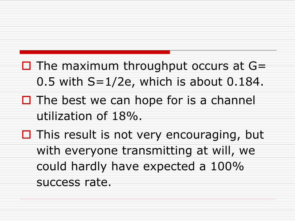
The maximum throughput occurs at G=
0.5 with S=1/2e, which is about 0.184.
The best we can hope for is a channel
utilization of 18%.
This result is not very encouraging, but
with everyone transmitting at will, we
could hardly have expected a 100%
success rate.

Slotted ALOHA
It’s basically a method for doubling the capacity of
an ALOHA system.
Aim was to divide time up into discrete intervals,
each interval corresponding to one frame.
This approach requires the users to agree of slot
boundaries.
One way to achieve synchronization would be to
have one special station emit a pip at the start of
each interval, like a clock. It has come to be known
as SLOTTED ALOHA
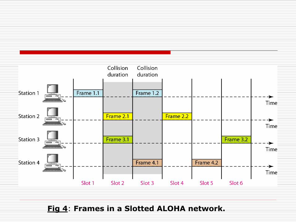
Fig 4: Frames in a Slotted ALOHA network.

In contrast to pure ALOHA, a computer
is not permitted to send whenever a
carriage return is typed.
Instead, it is required to wait for the
beginning of the next slot.
Thus the continuous pure ALOHA is
turned into discrete one & the
vulnerable period is now halved
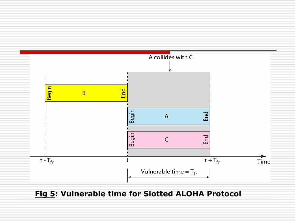
Fig 5: Vulnerable time for Slotted ALOHA Protocol
The best we can hope for using
slotted ALOHA is 37% of the slots
empty, 37% successes & 26%
collisions.
Small increase in the channel load
can drastically reduce its
performance.
Assignment
Explain Static Channel Allocation
Explain Pure & Slotted Aloha
ETHERNET – CSMA/CD
Section - C
Lecture – 22

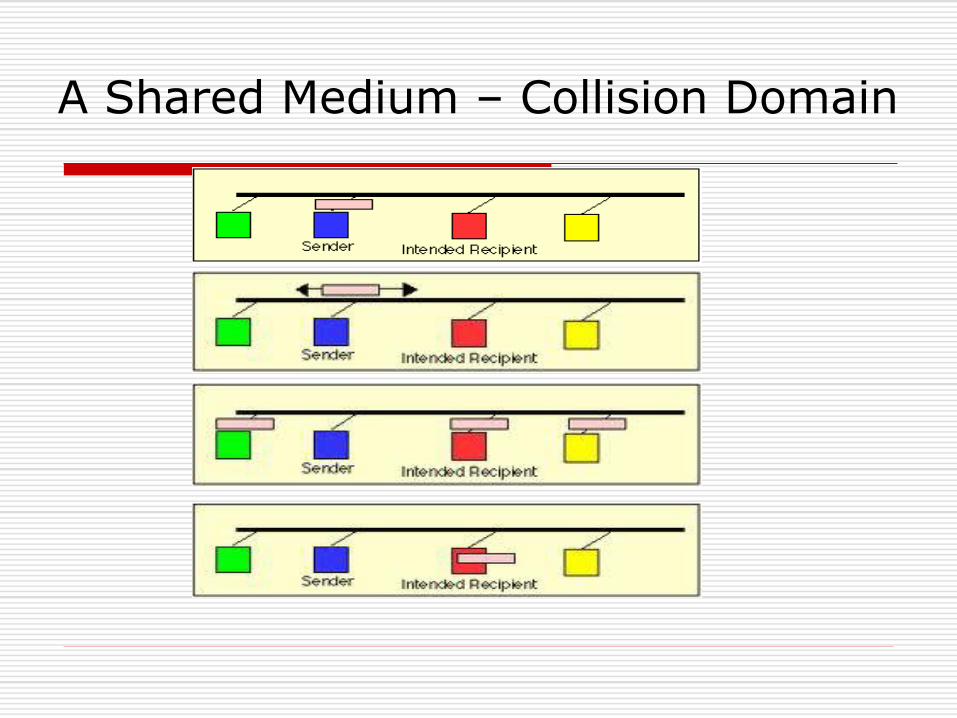
A Shared Medium – Collision Domain


Dynamic Channel Allocation Technologies
CSMA
CSMA/CD (old ETHERNET)
Switching (Fast ETHERNET)
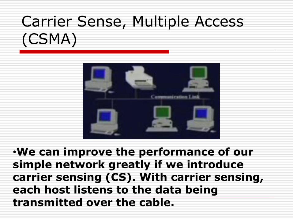
Carrier Sense, Multiple Access (CSMA)
•We can improve the performance of our simple network greatly if we introduce carrier sensing (CS). With carrier sensing, each host listens to the data being transmitted over the cable.

Carrier Sense, Multiple Access (CSMA)
A host will only transmit its own frames when it cannot hear any data being transmitted by other hosts.
When a frame finishes, an interframe gap of about 9.6 µsec is allowed to pass before another host starts transmitting its frame.

CSMA Collisions
Collisions can still occur:
Propagation delay means two nodes may not hear each other’s transmission.
Collision:
Entire packet transmission wasted
note
Role of distance & propagation delay determining collision probability.
CSMA
CSMA : listen before transmit. If channel is sensed busy, defer transmission.
Persistent CSMA: retry immediately when channel becomes idle ( this may cause instability)
p- persistant – retry with probability p.

Non persistent CSMA: retry after random interval.
Note: collisions may still exist, since two stations may sense the channel idle, at the same time (or better, within a “vulnerable” window = round trip delay)
In case of collision, the entire packet transmission time is wasted.

Comparison of Channel Utilization
G (Attempts per packet time)

CSMA/CD (Collision Detection
CSMA/CD: carrier sensing, deferral as in CSMA
Collisions detected with short time
Colliding transmissions aborted, reducing channel wastage.
Collision Detection
Easy in wired LANs : measure signal strengths, compare transmitted, received signals.
CSMA/CD is difficult in wireless LANs:
receiver shut off while transmitting.
Ethernet
“dominant” LAN technology:
Cheap $20 for 100Mbs!
First widely used LAN technology.
Simpler, cheaper than token LANs and ATM Metcalfe’s Ethernet sketch
Kept up with speed race: 10, 100, 1000 Mbps.

Ethernet
Ethernet LAN. IEEE 802.3
Carrier Sense Multiple Access / Collision Detection
(CSMA/CD) is used.
Ethernet uses a bus topology.
In CSMA/CD, each station has equal access to the
network, but it can broadcast only when the network is
idle. Before transmitting, a station: (1)-listens to the
network to sense if another workstation is transmitting
(carrier sense). If the network is still idle after a
certain period, (2) – the station will transmit.
Ethernet LAN. IEEE 802.3
It is possible that two stations will listen and sense an idle network at the same time. Each will then transmit its message on the network, where the messages will collide. Neither message will be usable if collision occurs

Ethernet LAN. IEEE 802.3
While transmitting a station must perform collision
detection to detect if its message was destroyed,
If a collision is detected, the detecting station
broadcasts a collision or jam signal to alert other
stations that a collision has occurred. Each
transmitting station then waits a random amount of
time (ranging from 10 to 90 ms) before attempting
the transmission again.

Ethernet CSMA/CD Algorithm
1. Adapter gets datagram from N/W Layer and creates frame.
2. If adapter senses channel is idle, it starts to transmit frame. If it senses channel busy, waits until channel idle and then transmits.
3. If adapter transmits entire frame without detecting another transmission, the adapter is done with frame.

Ethernet CSMA/CD
4. If adapter detects another transmission while transmitting, aborts and sends jam signal.
5. After aborting, adapter enters exponential backoff algorithm: after the m-th collision, another chooses a K at random from
{0,1,2,…. 2m – 1}. Adapter waits K=512 bit times and returns to Step 2.

Ethernet CSMA/CD
Jam Signal : make sure all other transmitters are aware of collision.
Backoff: Bit time 0.1 microsec for 10 Mbps Ethernet; for K = 1023, wait time is about 50 msec.

Exponential Back off Algorithm
Goal: adapt retransmission attempts to estimated current load.
Heavy load: random wait will be longer.
First collision: choose K from {0,1}; delay is K* 512 bit transmission times.
After second collision: choose K from {0,1,2,3}….
After ten collisions, choose K from {0,1,2,3,4….1023}
CSMA with Collision Detection
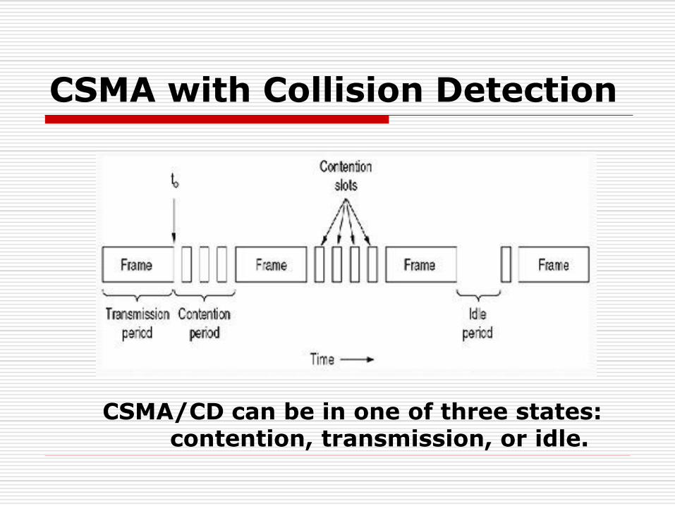
CSMA/CD can be in one of three states: contention, transmission, or idle.

IEEE 802.3: CSMA/CD Bus LAN
Besides carrier sensing, collision detection and the binary exponential back-of algorithm, the standard also describes the format of the frames and the type of encoding used for transmitting frames.

IEEE 802.3 : CSMA/CD Bus LAN
The minimum length of frames can be varied from network to network. This is important because, depending on the size of the network, the frames must be of a suitable minimum length.
The standard also makes some suggestions about the type of cabling that should be used for CSMA/CD bus LANs.

Time to Detect Collision
Collision detection can take as long as 2Ʈ

IEEE 802.3: Minimum Frame Length
To ensure that no node may completely receive a frame before the transmitting node has finished sending it, Ethernet defines a minimum frame size (i.e. no frame may have less than 46 bytes of payload.)
The minimum frame size is related to the distance which the network spans, the type of media being used and the number of repeaters which the signal may have to pass through to reach the furthest part of the LAN.
Together these define a value known as the Ethernet Slot Time, corresponding to 512 bit times at 10Mbps.

Lecture – 23
More about CSMA
Carrier Sense Multiple Access Protocols (CSMA)
Problem with ALOHA: low throughput because the
collision wastes transmission bandwidth.
Solution: avoid transmission that are certain to cause
collision, that is CSMA. Any station listens to the
medium, if there is some transmission going on the
medium, it will postpone its transmission.
In Local Area Network, it is possible for stations to detect
what other stations are doing & adapt their behavior
accordingly.
Protocols in which stations listen for a carrier ( i.e. a
transmission) & act accordingly are called Carrier
Sense Protocols.
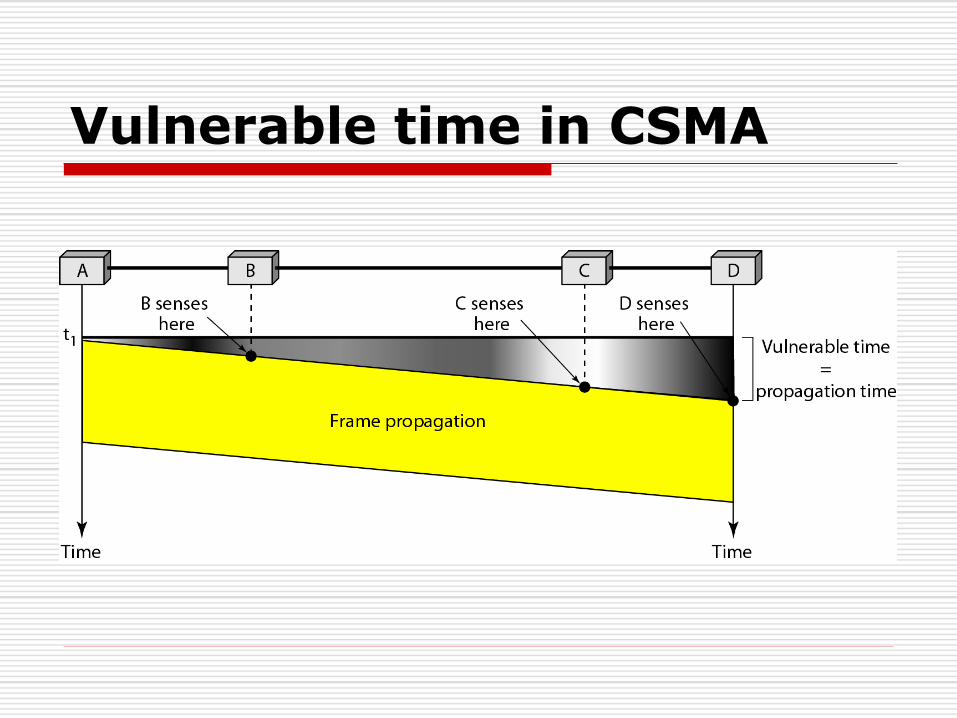
Vulnerable time in CSMA

CSMA Types:
1-Persistent CSMA
Non–Persistent CSMA
p – Persistent CSMA
I. 1-Persistent Protocol
When a station has data to send, it first listens to the channel to see if anyone else
is transmitting at that moment. If the channel is busy, the station waits until it
becomes idle.
When the station detects an idle channel, it transmits a frame.
If a collision occurs, the station waits a random amount of time and starts all over
again. The protocol is called 1-persistent because the station transmits with a
probability of 1 when it finds the channel idle.
The propagation delay has an important effect on the performance of the protocol.
There is a small chance that just after a station begins sending, another station will
become ready to send and sense the channel.
If the first station's signal has not yet reached the second one, the latter will sense
an idle channel and will also begin sending, resulting in a collision.
The longer the propagation delay, the more important this effect becomes, and the
worse the performance of the protocol.

1-Persistent Protocol is far better than
pure ALOHA because both stations have
the decency to desist from interfering
with the third station's frame. Intuitively,
this approach will lead to a higher
performance than pure ALOHA. Exactly
the same holds for slotted ALOHA.

Behavior of Three Persistent methods:

II. Non Persistent CSMA.
In this protocol, a conscious attempt is made to be
less greedy than in the previous one.
Before sending, a station senses the channel. If no
one else is sending, the station begins doing so itself.
However, if the channel is already in use, the station
does not continually sense it for the purpose of
seizing it immediately upon detecting the end of the
previous transmission.
Instead, it waits a random period of time and then
repeats the algorithm.
Difference
Non-Persistent algorithm leads
to better channel utilization but
longer delays than 1-persistent
CSMA.

P- Persistent CSMA
It applies to slotted channels and works as follows :
When a station becomes ready to send, it senses the channel.
If it is idle, it transmits with a probability p.
With a probability q = 1 - p, it defers until the next slot.
If that slot is also idle, it either transmits or defers again, with
probabilities p and q.
This process is repeated until either the frame has been
transmitted or another station has begun transmitting.
In the latter case, the unlucky station acts as if there had been a
collision (i.e., it waits a random time and starts again).
If the station initially senses the channel busy, it waits until the
next slot and applies the above algorithm.

Figure shows the computed throughput versus offered traffic for all three protocols, as well as for pure and slotted ALOHA.
Persistent and non persistent CSMA
protocols are clearly an improvement over
ALOHA because they ensure that no
station begins to transmit when it senses
the channel busy.
Another improvement is for stations to
abort their transmissions as soon as they
detect a collision.

CSMA with Collision Detection
if two stations sense the channel to be idle and begin
transmitting simultaneously, they will both detect the
collision almost immediately.
Rather than finish transmitting their frames, which are
irretrievably garbled anyway, they should abruptly stop
transmitting as soon as the collision is detected.
Quickly terminating damaged frames saves time and
bandwidth. This protocol, known as CSMA/CD (CSMA
with Collision Detection) is widely used on LANs in
the MAC sublayer.
In particular, it is the basis of the popular
Ethernet, LAN
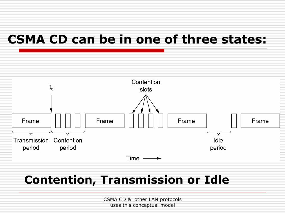
CSMA CD & other LAN protocols uses this conceptual model
CSMA CD can be in one of three states:
Contention, Transmission or Idle

Basic Concept
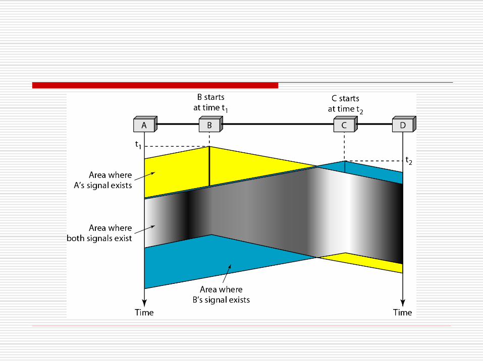
At the point marked to, A station has finished transmitting its frame.
Any other station having a frame to send may now attempt to do so.
If two or more stations decide to transmit simultaneously, there will be
a collision.
Collisions can be detected by looking at the power or pulse width of
the received signal and comparing it to the transmitted signal.
After a station detects a collision, it aborts its transmission, waits a
random period of time, and then tries again, assuming that no other
station has started transmitting in the meantime.
Therefore, our model for CSMA/CD will consist of alternating
contention and transmission periods, with idle periods occurring when
all stations are quiet (e.g., for lack of work).

It is important to realize that collision detection
is an analog process.
The station's hardware must listen to the cable
while it is transmitting.
If what it reads back is different from what it is
putting out, it knows that a collision is
occurring.
The implication is that the signal encoding
must allow collisions to be detected, For this
reason, special encoding is commonly used.
It is also worth noting that a sending station
must continually monitor the channel, listening
for noise bursts that might indicate a collision.
For this reason, CSMA/CD with a single channel
is inherently a half-duplex system. (A half-
duplex system provides for communication in both directions, but only
one direction at a time, not simultaneously.)
It is impossible for a station to transmit and
receive frames at the same time because the
receiving logic is in use, looking for collisions
during every transmission.
To avoid any misunderstanding, it is
worth noting that no MAC-sublayer
protocol guarantees reliable delivery.
Even in the absence of collisions, the
receiver may not have copied the
frame correctly for various reasons
(e.g., lack of buffer space or a missed
interrupt).

Energy Level during transmission, Idleness or Collision
CSMA with Collision Avoidance (CSMA/CA)
In CSMA/CA, if the station finds the
channel busy, it does not restart the
timer of the contention window;
it stops the timer and restarts it when
the channel becomes idle.
Note

Timing in CSMA/CA

Assignment
Explain CSMA
CSMA/CD
CSMA/CA
Lecture – 24

MAC and LLC
In any broadcast network, the stations
must ensure that only one station transmits
at a time on the shared communication
channel
The protocol that determines who can
transmit on a broadcast channel are called
Medium Access Control (MAC) protocol
The MAC protocol are implemented
in the MAC sublayer which is the
lower sublayer of the data link layer
The higher portion of the data link
layer is often called Logical Link
Control (LLC)
Logical Link
Control
Medium Access
ControlData
Lin
k
Layer
to Physical Layer
to Network Layer

IEEE 802 Standards
IEEE 802 is a family of standards for LANs, which defines an LLC and several MAC sublayers
80
2.3
80
2.4
80
2.5
80
2.1
1
802.2
802.1
IEEE 802 standard
Medium
Access
Control
Physical
Layer
Logical Link
Control
IEEE
Reference
Model
Physical
Layer
Data Link
Layer
Higher
Layer

Multiple Access Methods
Fixed assignment
Partition channel so each node gets a slice of the
bandwidth
Essentially circuit switching – thus inefficient
Examples: TDMA, FDMA, CDMA (all used in
wireless/cellular environments)
Contention-based
Nodes contends equally for bandwidth and recover from collisions
Examples: Aloha, Ethernet
Token-based or reservation-based
Take turns using the channel
Examples: Token ring

A Quick Word about Token Ring
Developed by IBM in early 80’s as a new LAN architecture
Consists of nodes connected into a ring (typically via
concentrators)
Special message called a token is passed around the ring
When nodes gets the token it can transmit for a limited
time
Every node gets an equal opportunity to send
IEEE 802.5 standard for Token Ring
Designed for predictability, fairness and reliability
Originally designed to run at either 4Mbps and 16Mbps
Still used and sold but beaten out by Ethernet
Our Focus is Ethernet History
Developed by Bob Metcalfe and others at Xerox PARC in mid-1970s
Roots in Aloha packet-radio network
Standardized by Xerox, DEC, and Intel in 1978
LAN standards define MAC and physical layer connectivity
IEEE 802.3 (CSMA/CD - Ethernet) standard – originally 2Mbps
IEEE 802.3u standard for 100Mbps Ethernet
IEEE 802.3z standard for 1,000Mbps Ethernet
CSMA/CD: Ethernet’s Media Access Control (MAC) policy
CS = carrier sense
Send only if medium is idle
MA = multiple access
CD = collision detection
Stop sending immediately if collision is detected

Ethernet Cabling
The name ''Ethernet'' refers to the cable (the ether),
Speed: 10Mbps -10 Gbps
Standard: 802.3, Ethernet II (DIX)
Most popular physical layers for Ethernet:
10Base5 Thick Ethernet: 10 Mbps coax cable
10Base2 Thin Ethernet: 10 Mbps coax cable
10Base-T 10 Mbps Twisted Pair
100Base-TX 100 Mbps over Category 5 twisted pair
100Base-FX 100 Mbps over Fiber Optics
1000Base-FX 1Gbps over Fiber Optics
10000Base-FX 1Gbps over Fiber Optics (for wide area
links)

Thicknet (10Base5)
10Base5 Cabling
Historically, 10Base5 cabling, popularly called
thick Ethernet, came first.
It resembles a yellow garden hose, with
markings every 2.5 meters to show where the
taps go.
(The 802.3 standard does not actually require
the cable to be yellow, but it does suggest it.)
Connections to it are generally made using
vampire taps, in which a pin is very carefully
forced halfway into the coaxial cable's core.

10Base5 Cabling (continued)
The notation 10Base5 means that it operates at 10
Mbps, uses baseband signaling, and can support
segments of up to 500 meters.
The first number is the speed in Mbps.
Then comes the word ''Base'' (or sometimes ''BASE'') to
indicate baseband transmission.
There used to be a broadband variant, 10Broad36, but
it never caught on in the marketplace and has since
vanished.
Finally, if the medium is coax, its length is given
rounded to units of 100 m after ''Base.''

10Base5 (Thick Coax)
Advantages: Low attenuation, excellent
noise immunity, superior mechanical
strength
Disadvantages: Bulky, difficult to pull,
transceiver boxes too expensive
* Wiring represented a significant part
of total installed cost.

Ethernet Technologies: 10Base2
10: 10Mbps; 2: under 185 (~200) meters cable length
Thin coaxial cable in a bus topology
Repeaters used to connect multiple segments
Repeater repeats bits it hears on one interface to its other interfaces:
physical layer device only!

10Base2 cont..
Historically, the second cable type was 10Base2, or
thin Ethernet, which, in contrast to the garden-
hose-like thick Ethernet, bends easily.
Connections to it are made using industry-
standard BNC connectors to form T junctions,
rather than using vampire taps.
BNC connectors are easier to use and more reliable.
Thin Ethernet is much cheaper and easier to install,
but it can run for only 185 meters per segment,
each of which can handle only 30 machines.

10Base2 (Coax)- coax thinner & lighter
Advantages: Easier to install, reduced
hardware cost, BNC connectors widely
deployed lower installation costs.
Disadvantages: Attenuation not as
good, could not support as many stations
due to signal reflection caused by BNC
Tee Connector.

10BaseT and 100BaseT
10/100 Mbps rate
T stands for Twisted Pair
Hub(s) connected by twisted pair facilitate “star topology”
Distance of any node to hub must be < 100M

The problems with finding cable breaks helps
systems to use a different kind of wiring pattern, in
which all stations have a cable running to a
central hub in which they are connected
electrically.
Usually, these wires are telephone company
twisted pairs, since most office buildings are
already wired this way, and normally plenty of
spare pairs are available. This scheme is called
10Base-T.
Hubs do not buffer incoming traffic.

Physical Layer Configurations for 802.3
Physical layer configurations are specified in three parts
Data rate (10, 100, 1,000)
10, 100, 1,000Mbps
Signaling method (base, broad)
Baseband
Digital signaling
Broadband
Analog signaling
Cabling (2, 5, T, F, S, L)
5 - Thick coax (original Ethernet cabling)
F – Optical fiber
S – Short wave laser over multimode fiber
L – Long wave laser over single mode fiber
Technology Options
Ethernet
Fast Ethernet
Gigabit Ethernet
10 Gig Ethernet
WLAN

Ethernet Evolution
Ethernet Evolution
Standard ethernet
Fast ethernet
Gigabit ethernet
Ten-gigabit ethernet
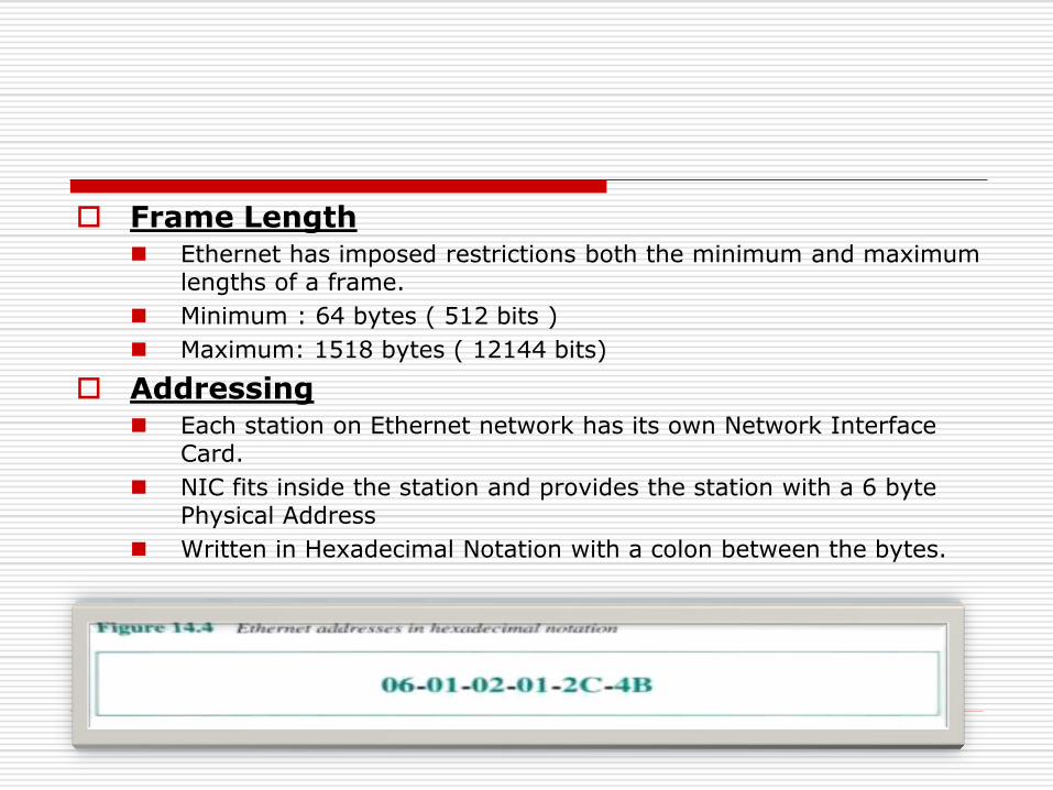
Frame Length Ethernet has imposed restrictions both the minimum and maximum
lengths of a frame.
Minimum : 64 bytes ( 512 bits )
Maximum: 1518 bytes ( 12144 bits)
Addressing Each station on Ethernet network has its own Network Interface
Card.
NIC fits inside the station and provides the station with a 6 byte Physical Address
Written in Hexadecimal Notation with a colon between the bytes.

Ethernet Addressing
End nodes are identified by their Ethernet Addresses (MAC Address or Hardware Address) which is a unique 6 Byte address.
MAC Address is represented in Hexa Decimal format e.g 00:05:5D:FE:10:0A
The first 3 bytes identify a vendor (also called prefix) and the last 3 bytes are unique for every host or device

Standard Ethernet cont…
Unicast and Muticast Source address is always unicast - frame comes from one station
Destination address can be unicast or multicast
LSB of the first byte of address defines whether it is unicast or multicast.
If the bit is 0 the it is unicast if the bit is 1 then it is multicast
Access Method: CSMA / CD Standard Ethernet uses 1-Persistent CSMS/CD

Categories Of Standard Ethernet
10BaseF: FIBER ETHERNET
It uses a Star Topology to connect
stations to hub.
The stations are connected to a hub
via two fiber optic cable
Maximum length of the fiber optic cable
can be 2000 m
Ethernet Layer 2 & Layer 3 Switching Evolution
Layer 2 switches are frequently installed in the
enterprise for high-speed connectivity between
end stations at the data link layer.
Layer 3 switches are a relatively new
phenomenon, made popular by (among others)
the trade press.

Bridging (Switching) Technology
Bridging technology has been around since the
1980s (and maybe even earlier).
Bridging involves segmentation of local-area
networks (LANs) at the Layer 2 level.
A multiport bridge learns about the Media Access
Control (MAC) addresses on each ports and passes
MAC frames to its destination ports.
These bridges also ensures that frames meant for
MAC addresses available at the same ports are not
forwarded to the other ports.

Layer 2 Switching
Layer 2 switches effectively provide the
same functionality as Switching.
They are similar to multiport bridges &
forward frames on each port.
Major Difference is the involvement of
hardware that ensures that multiple
switching paths inside the switch can be
active at the same time.
Example
Consider Figure, which shows a four-port
switch with stations A on port 1, B on port 2, C
on port 3 and D on port 4.
Assume that A desires to communicate with B,
and C desires to communicate with D.
In a single CPU bridge, this forwarding would
be done in software, where the CPU would pick
up frames from each of the ports sequentially
and forward them to appropriate output ports.

FIGURE: Layer 2 Switch with External router for inter VLAN traffic & connecting to the Internet.
This process is highly inefficient
in a scenario, where the traffic
between A and B has no relation
to the traffic between C and D.

Solution: Hardware-based Layer 2 switching
Layer 2 switches with their hardware support are able to
forward such frames in parallel so that A and B and C and D
can have simultaneous conversations.
The parallel-ism has many Advantages. Assume that A and B
are NetBIOS stations, while C and D are Internet Protocol
(IP) stations. There may be no reason for the communication
between A and C and A and D. Layer 2 switching allows this
coexistence without sacrificing efficiency.
NetBIOS is an acronym for Network Basic Input/Output System.
It provides services related to the session layer of the OSI model allowing applications on separate computers to communicate over local area network.

Virtual LANs
VLAN, is a group of hosts with a common set of requirements that
communicate as if they were attached to the same broadcast
domain, regardless of their physical location.
In reality however LANs are rarely so clean.
Assume a situation where A,B,C, and D are all IP stations. A and B
belong to the same IP subnet, while C and D belong to a different
subnet.
Layer 2 switching is fine, as long as only A and B or C and D
communicate.
If A and C, which are on two different IP subnets, need to
communicate, Layer 2 switching is inadequate? the communication
requires an IP router.
A corollary of this is that A and B and C and D belong to different
broadcast domains. that is, A and B should not *see* the MAC layer
broadcasts from C and D, and vice versa.

A popular classification of Layer 2 switches is
Cut through Vs. Store & Forward
Cut-through switches make the forwarding
decision as the frame is being received by just
looking at the header of the frame.
Store-and-forward switches receive the
entire Layer 2 frame before making the
forwarding decision.
Layer 3 Switching
Layer 3 switching is a relatively
new term, which has been
*extended* by a numerous
vendors to describe their products.
Layer 3 switches are super fast
routers that do Layer 3 forwarding
in hardware.
IP is the most common among all Layer 3
protocols today, most of the Layer 3 switches
today perform IP switching at the hardware level
and forward the other protocols at Layer 2 (that
is, bridge them).
The second issue of complicated Layer 3
forwarding decisions is best illustrated by IP
option processing, which typically causes the
length of the IP header to vary, complicating the
building of a hardware forwarding engine.
However, a large number of IP packets do not
include IP options;
so, it may be overkill to design this processing
into silicon.
The compromise is that the most common (fast
path) forwarding decision is designed into
silicon, whereas the others are handled
typically by a CPU on the Layer 3 switch.

Summary
To summarize, Layer 3 switches are routers
with fast forwarding done via hardware. IP
forwarding typically involves a route
lookup,
And forwarding the frame with the
appropriate MAC header to the correct
output port. Lookups can be done in
hardware

Lecture – 25

Fast Ethernet (100Base-T)
How to achieve 100 Mbps capacity?
LLC
MAC
Convergence Sublayer
Media Dependent Sublayer
Media Independent Interface
Data Link Layer
Physical Layer
Media Independent Interface provides three choices.
MII

FAST ETHERNET [IEEE 802.3u]
Three choices
The original Fast Ethernet cabling

100Base T

100 BASE T4
UTP (Unshielded Twisted Pair) Cable has a 30 MHz limit
Can use four separate twisted pairs of Cat 3 UTP
Utilize three pair in both directions (at 33 1/3 Mbps) with other pair for carrier sense/collision detection.
Three-level ternary code is used 8B/6T.
Prior to transmission each set of 8 bits is converted into 6 ternary symbols.

100BaseTX
Uses two pair of twisted pair, one pair for
transmission and one pair for reception.
Uses either STP or (Category) Cat 5 UTP.
There is a guaranteed signal transition at least
every two bits.
Gigabit Ethernet (IEEE 802.3z)
1. Provides speeds of 1000 Mbps (i.e., one billion
bits per second capacity) for half-duplex and
full-duplex operation.
2. Uses Ethernet frame format and MAC
technology
3. Uses 802.3 full-duplex Ethernet technology.
4. Uses 802.3x flow control.
5. All Gigabit Ethernet configurations are point-
to-point!
Gigabit Ethernet (1000 BASE X)
Full Duplex operation
• In the full duplex mode, there is a central switch connected to all
computers or other switches.
• In this mode, each switch has buffer for each input port in which
data are stored until they are transmitted.
• There is no collision in this mode. This means that CSMA/CD isn’t
used.
Half Duplex operation
• Gigabit Ethernet can also be used in half duplex mode, although
rare.
• In this case, a switch can be replaced by a hub, which acts as the
common cable in which collision might occur.
• The half duplex approach uses CSMA/CD.

Gigabit Ethernet Technology
Gigabit Ethernet Cabling

1000 BASE SX fiber - short wavelength
1000 BASE LX fiber - long wavelength
1000 BASE CX copper- shielded twisted pair
1000 BASE T copper-unshielded twisted pair
* Based on Fiber Channel physical signalling technology.
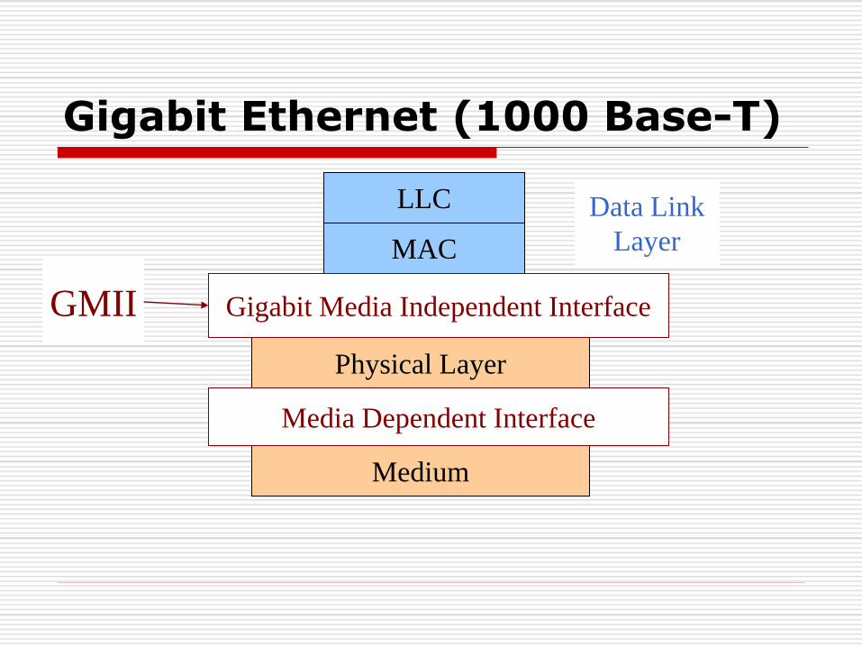
Gigabit Ethernet (1000 Base-T)
LLC
MAC
Medium
Physical Layer
Data Link
Layer
GMII Gigabit Media Independent Interface
Media Dependent Interface
Gigabit Media Independent Interface(GMII)
Allows any physical layer to be used
with a given MAC.
Namely, Fiber Channel physical layer
can be used with CSMA/CD.
Permits both full-duplex and half-
duplex.
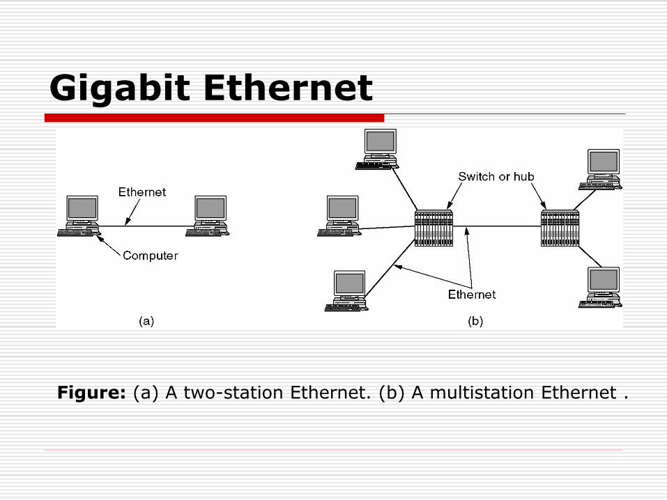
Gigabit Ethernet
Figure: (a) A two-station Ethernet. (b) A multistation Ethernet .

Summary of Ethernet Standards

Experiences with Ethernet
Ethernets work best under light loads
Utilization over 30% is considered heavy
Network capacity is wasted by collisions
Most networks are limited to about 200 hosts
Specification allows for up to 1024
Most networks are much shorter
5 to 10 microsecond RTT
Transport level flow control helps reduce load (number of
back to back packets)
Ethernet is inexpensive, fast and easy to administer!
Ethernet Problems
Ethernet’s peak utilization is pretty low (like Aloha)
Peak throughput worst with
More hosts
More collisions needed to identify single sender
Smaller packet sizes
More frequent arbitration
Longer links
Collisions take longer to observe, more wasted
bandwidth
Efficiency is improved by avoiding these conditions
Why did Ethernet Win?
There are LOTS of LAN protocols
Price
Performance
Availability
Ease of use
Scalability
Token Ring Defined
Token Ring is a standardized and
efficient network
Based on the token passing protocol (token passing is a channel access method where a signal
called a token is passed between nodes that authorizes
the node to communicate. The most well-known
examples are token ring )
Advantage of token passing collisions are eliminated
Conforms to the IEEE 802.5 standard

Token Ring Origin
Introduced by IBM in 1984 for connecting
the following:
Personal computers
Mid-range computers
Mainframe computers
Current position with IBM
Part of the SNA (System Network Architecture)
specification for interconnection related to IBM
products
Current Status of Token Ring Technology
Standardized
IEEE 802.5
Becoming overshadowed by Ethernet for LAN
applications due the following reasons
Higher speeds of Ethernet
Lower cost of Ethernet
Ethernet cabling borrows from the
telecommunication industry, hence it is
cheaper
Current Usage
In the 4-16 Mbps range, the token ring remains
an efficient LAN technology
100 Mbps Token Ring networks are now used in
the field
Token ring technology is used for the backbone in
large networks where the operating speed is in
the range of 100 Mbps
An example is FDDI (Fiber Distributed Data
Interface provides a 100Mbps optical standard for data
transmission in a local area network that can extend in range up to
200 kilometers (124 miles) )

AUI :
A Typical Token Ring LAN Configuration
Muti-Station Access Unit
Client Client Server
IBM Type 1 Twisted Pair
9-Pin AUI (Attachment Unit
Interface) Connectors
Special IBM Connectors
Topology
Logical Functioning
Ring
Physical Implementation
Star
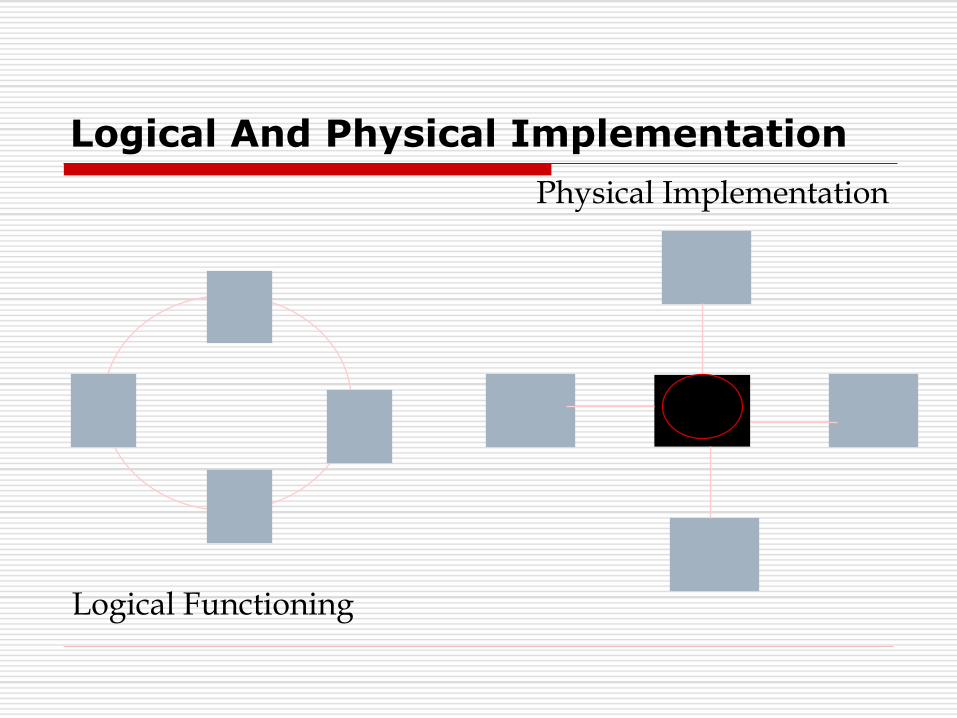
Logical And Physical Implementation
Logical Functioning
Physical Implementation
Cabling
Shielded or unshielded Twisted Pair
IBM
Types 1, 2, 3 etc.
Others
Access Method, Speed and Transmission
Access method
Token passing
IEEE standard
IEEE 802.5
Speed
4M, 16M and 100M bps
Transmission
Base band

Token Passing Access Method
Token
Origin
Destination
Data Delivery
Acknowledgment

Frame Format
Data
Start
Access Control
Frame Control
Destination Address
Source Address Frame Check Sequence
End Delimiter
Frame Status

Token Bus
Definition Bus: A single
communication line, typically a
twisted pair, coaxial cable, or optical
fiber, represents the primary
medium.
IEEE Standards :
802.4
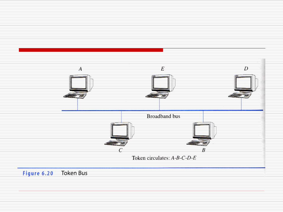

Token Bus vs. Token Ring
The token bus operates on the same principle as the
token ring. The stations are organized into a ring and
a token passes among them. A station wanting to
send something must wait for the token to arrive.
The stations communicate via a common bus in an
Ethernet.
Generally, a station receives a token from its
predecessor and sends a token to its successor.
Token bus stations must know their predecessor and
successor.

Token Bus Frame Format

Assignment
Explain IEEE Standards