lecture #21 photodetectors
TRANSCRIPT

EE 232: Lightwave Devices
Lecture #21 – Photodetectors
Instructor: Seth A. Fortuna
Dept. of Electrical Engineering and Computer Sciences
University of California, Berkeley
4/22/2019

2Fortuna – E3S Seminar
Absorption coefficient
H. Melchior, “Laser Handbook”, Vol. 1 pp 725-835 (1972).

3Fortuna – E3S Seminar
Photoconductor
+ _
d
V
Light off
semiconductor0 0 0( )n pJ q n p E = +
Light on
0 0( )n pJ J q p En + +
(assuming p-type semiconductorand low-injection)
( )
0( )ph n
n n
n t
nI J J A q EA
dq A G
=
= −
=
Photocurrent
generationelectronlifetime
transit time
/# carriers injected
(V )o (lume)( ) )(s
opt hG
P
A d
= =
where (1 )(1 )t
i R e −−= −
surfacereflectance
absorption
t

4Fortuna – E3S Seminar
Photoconductive gain
opt nph
t
PI
hq
=
photoconductivegain
Putting it all together,
injectedprimary
photocurrent
Illustration of photoconductive gain.An electron can contribute multipletimes to photocurrent.
Responsivity is Rh
q
=
and has units of amps / watt
Photogeneratedelectronexitssemiconductor
Second electronexits
Third electronexits
Second electronenters
Thirdelectronenters
Photo-generatedhole exits
Time
Positionx=0 x=d

5Fortuna – E3S Seminar
Photoconductor high-frequency response
)( )
(n
d nnG t
dt
t
= −
0 [ ( )( ) Re ]i tn nt en −= +
0 [ ( )( ) Re ]i tG Gt eG −= +
/(
( ))
)(
opt
n
P hi
A d
nn
= −−
1
/ 1
( )( ) 1
1
n
opt n
p n
p n
opt t n
A d i
qv
h
hn
P
I nA
I q
v iP
=
=
−
=
−
Let,
Then,
Note:
etc…
/ 1n t =
/ 10n t =
/ 100n t =
/ 1000n t =
/ 10000n t =

6Fortuna – E3S Seminar
p-i-n photodiode
+ _
d
p i n
-V
Ener
gyE-
fiel
d
Position
Position
p-i-n photodiode: Undoped orlightly doped semiconductorinserted between p and n-typesemiconductor. p and n-type regionsmay be higher bandgap than intrinsic region.Low noise and capable of high-speed.
cEvE
dark phI I I= +
0 1
h
qV
kTdark
opt
p
I I
P
hq
e
I
−
= −
(1 )(1 )d
i R e −−= −
7Fortuna – E3S Seminar
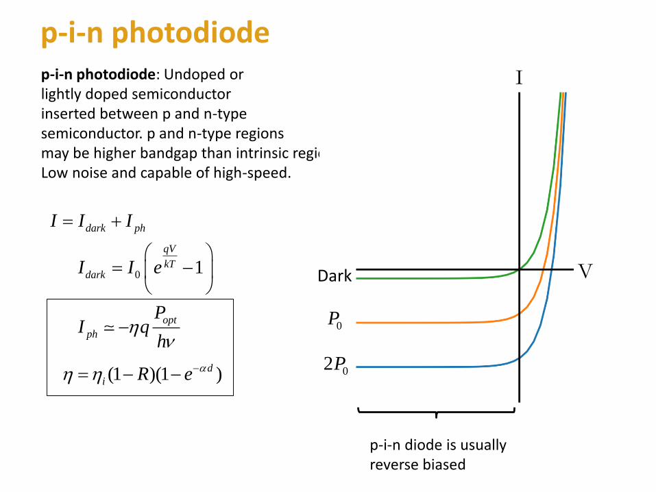
p-i-n photodiodep-i-n photodiode: Undoped orlightly doped semiconductorinserted between p and n-typesemiconductor. p and n-type regionsmay be higher bandgap than intrinsic region.Low noise and capable of high-speed.
dark phI I I= +
0 1
h
qV
kTdark
opt
p
I I
P
hq
e
I
−
= −
(1 )(1 )d
i R e −−= −
I
VDark
0P
02P
p-i-n diode is usuallyreverse biased

8Fortuna – E3S Seminar
Two types of p-i-n photodiodes
i
p
n
i
p
n
substratesubstrate
Surface illuminated p-i-n waveguide p-i-n
(1 )(1 )d
i R e −−= −
d
L
(1 )(1 )L
i R e −−= −
confinementfactor
d

9Fortuna – E3S Seminar
p-i-n high-frequency response
Time constant of hole transit across intrinsic region:
RC time constant:
t
h
d
v =
RCd
AR =
Surface illuminated p-i-n waveguide p-i-n
Speed usually limited by hole transit time
3
1(1 )(1 )
2
1
2
/ 2
d hdB i
hi
i h
vf R e
v
d
v
dd
−
=
− − =
3
1
2
hdB
vf
d
Efficiency-bandwidth product
Speed usually limited by RC time
3
1(1 )(1 )
2
1
2
2
L
dB i
i
i
df
w
L
R eR
A
d
d
R
A
R
− =
=
− −
3
1
2dB
A
df
REfficiency-bandwidth product
w: waveguidewidth

10Fortuna – E3S Seminar
BW-efficiency product(surface illuminated p-i-n)
Stephen B. Alexander. Optical communication receiver design. 1997.

11Fortuna – E3S Seminar
Avalanche photodiode (APD)
+ _
p+ i n+
-V
Ener
gyE-
fiel
d
Position
Position
cEvE
p
absorption
gain
APD: High-field region acceleratescarriers resulting in impact ionizationand creation of new carriers (avalanchebreakdown). Unlike the p-i-n, the APDhas gain. A single e-h pair can createa cascade of several others.Downside is additional noise.
opt
ph MP
qIh
=
multiplicationfactor
(1 )(1 )ad
i R e −
−= −
ad gd

12Fortuna – E3S Seminar
Impact ionization and multiplication factor
p
n
k
=
p
n
k
: electron ionization coefficient
: hole ionization coefficient
: ionization ratio
Usually k << 1 is desirable for good noise properties (more on this later).For example, silicon is an excellent material for APD.When only electrons are injected into the gain region, it can be shown:
(1 )
1n gkn d
k
e kM
− −
−=
−(electron multiplication factor)
MaterialSiGeInGaAs
k-value0.02-0.050.7-1.00.5-0.7

13Fortuna – E3S Seminar
APD high-frequency response
High-frequency response limited by hole transit time and gain build-up time.
hole transit timea g a
h
h h
d d d
v v
+=
gain build-up time m
n
gnM kd
v =
n
m
n
g
h
M kd
v →Usually, 3
1
2
n
n
dB
g
fv
M kd
Gain-bandwidth product
32 2
n e edB
g gn
M v v
MM f
kd kd = Typical values are 100 to 200 GHz

14Fortuna – E3S Seminar
Summary
Photodetector
Photoconductor
p-i-n
APD
Pros
Simple device,Gain,Very fast
Low noise,Fast
Gain,Fast,Increasedsensitivity(sometimes)
Cons
High noise
No gain
Complicated,Multiplication noise
phI
optq M
P
h
opt
hq
P
opt n
t
P
hq
Recommended reading: S.D. Personick, Optical Detectors and Receiver. J. Light. Technol. Vol. 26, No. 9, 2008.