lecture 25 - how the kinect works - cp fall 2011
TRANSCRIPT

12/01/11
How the Kinect Works
Computational Photography
Derek Hoiem, University of Illinois
Photo frame-grabbed from: http://www.blisteredthumbs.net/2010/11/dance-central-angry-review
T2
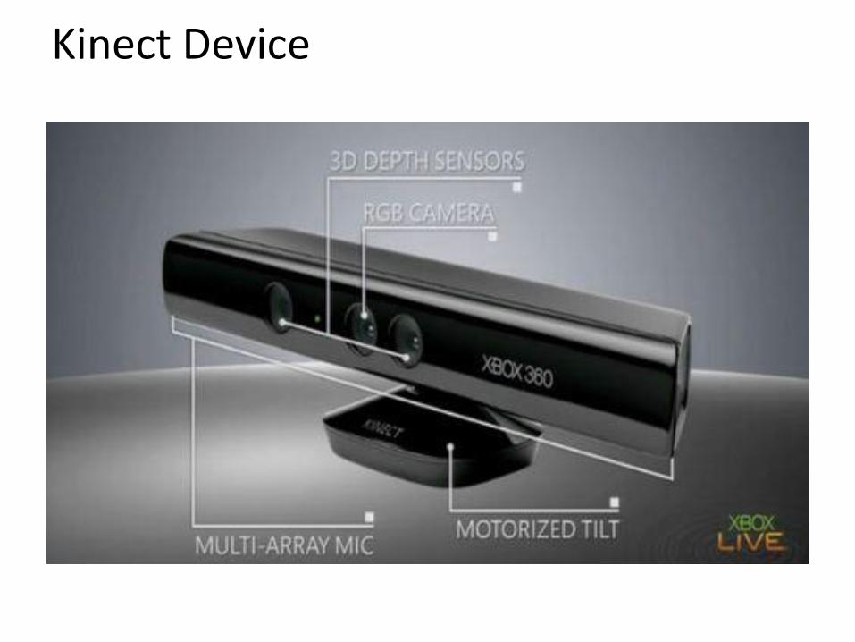
Kinect Device
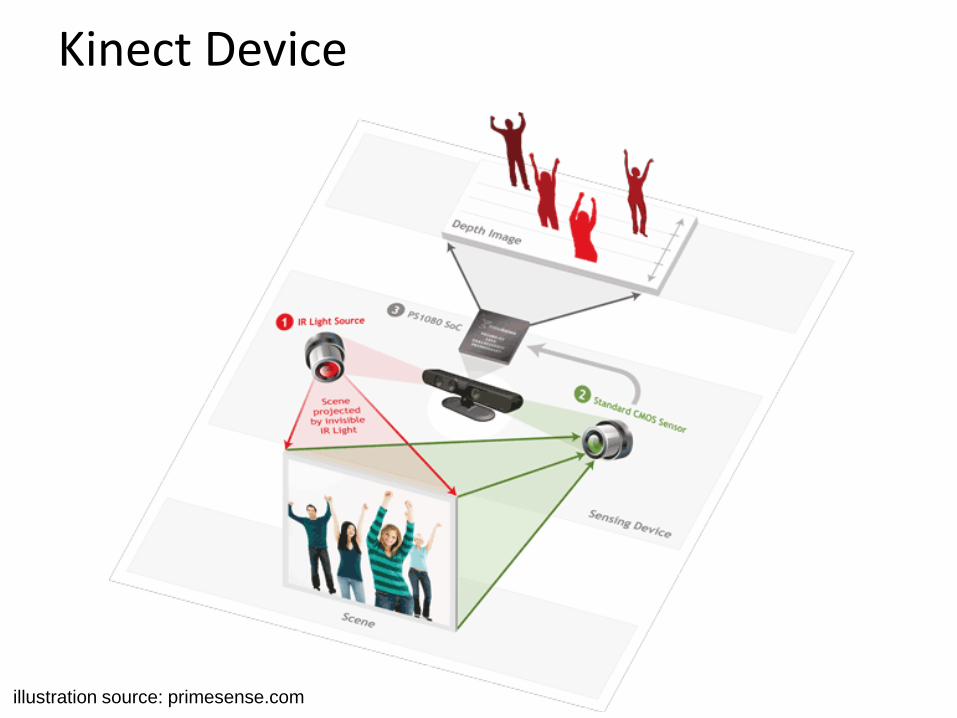
Kinect Device
illustration source: primesense.com
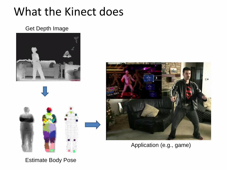
What the Kinect does Get Depth Image
Estimate Body Pose
Application (e.g., game)
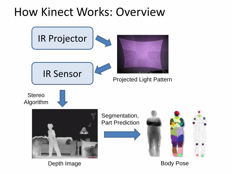
How Kinect Works: Overview
IR Projector
IR Sensor Projected Light Pattern
Depth Image
Stereo
Algorithm
Segmentation,
Part Prediction
Body Pose

Part 1: Stereo from projected dots
IR Projector
IR Sensor Projected Light Pattern
Depth Image
Stereo
Algorithm
Segmentation,
Part Prediction
Body Pose

Part 1: Stereo from projected dots
1. Overview of depth from stereo
2. How it works for a projector/sensor pair
3. Stereo algorithm used by Primesense (Kinect)

Depth from Stereo Images
image 1 image 2
Dense depth map
Some of following slides adapted from Steve Seitz and Lana Lazebnik

Depth from Stereo Images
• Goal: recover depth by finding image coordinate x’ that corresponds to x
f
x x’
Baseline
B
z
C C’
X
f
X
x
x'
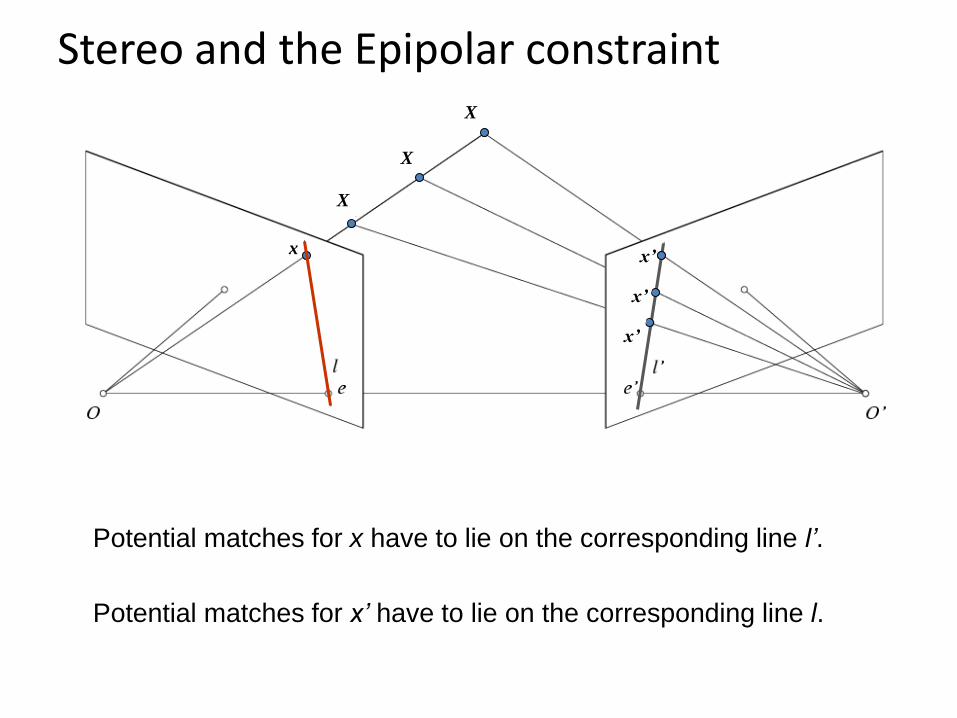
Potential matches for x have to lie on the corresponding line l’.
Potential matches for x’ have to lie on the corresponding line l.
Stereo and the Epipolar constraint
x x’
X
x’
X
x’
X
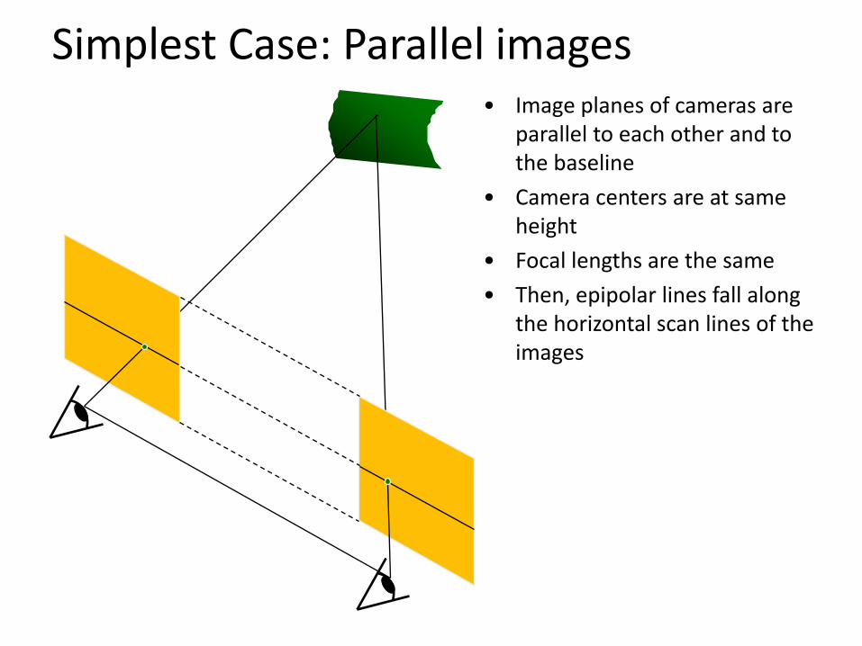
Simplest Case: Parallel images • Image planes of cameras are
parallel to each other and to the baseline
• Camera centers are at same height
• Focal lengths are the same
• Then, epipolar lines fall along the horizontal scan lines of the images
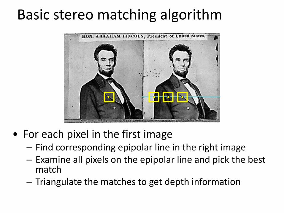
Basic stereo matching algorithm
• For each pixel in the first image – Find corresponding epipolar line in the right image – Examine all pixels on the epipolar line and pick the best
match – Triangulate the matches to get depth information
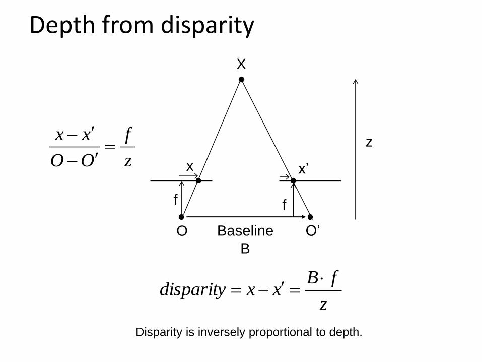
Depth from disparity
f
x’
Baseline
B
z
O O’
X
f
z
fBxxdisparity
Disparity is inversely proportional to depth.
x z
f
OO
xx

Basic stereo matching algorithm
• If necessary, rectify the two stereo images to transform epipolar lines into scanlines
• For each pixel x in the first image – Find corresponding epipolar scanline in the right image – Examine all pixels on the scanline and pick the best match x’ – Compute disparity x-x’ and set depth(x) = fB/(x-x’)

Matching cost
disparity
Left Right
scanline
Correspondence search
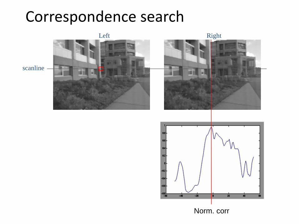
• Slide a window along the right scanline and compare contents of that window with the reference window in the left image
• Matching cost: SSD or normalized correlation

Left Right
scanline
Correspondence search
SSD
Left Right
scanline
Correspondence search
Norm. corr
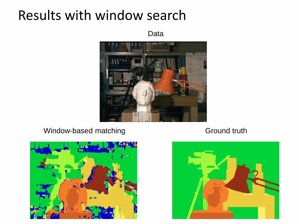
Results with window search
Window-based matching Ground truth
Data
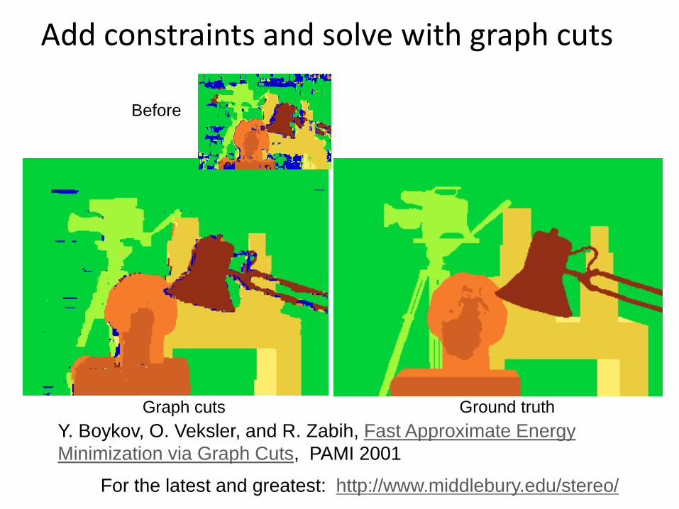
Add constraints and solve with graph cuts
Graph cuts Ground truth
For the latest and greatest: http://www.middlebury.edu/stereo/
Y. Boykov, O. Veksler, and R. Zabih, Fast Approximate Energy
Minimization via Graph Cuts, PAMI 2001
Before
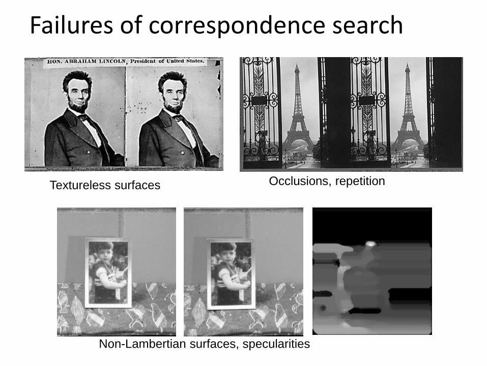
Failures of correspondence search
Textureless surfaces Occlusions, repetition
Non-Lambertian surfaces, specularities

Dot Projections
http://www.youtube.com/
watch?v=28JwgxbQx8w
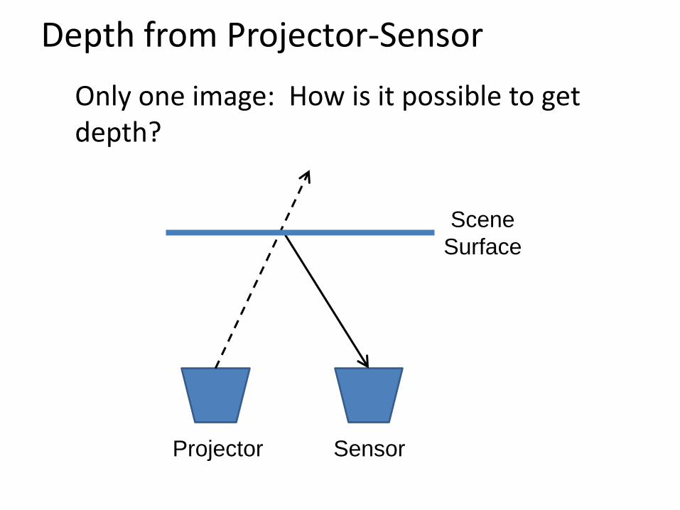
Depth from Projector-Sensor
Only one image: How is it possible to get depth?
Projector Sensor
Scene
Surface
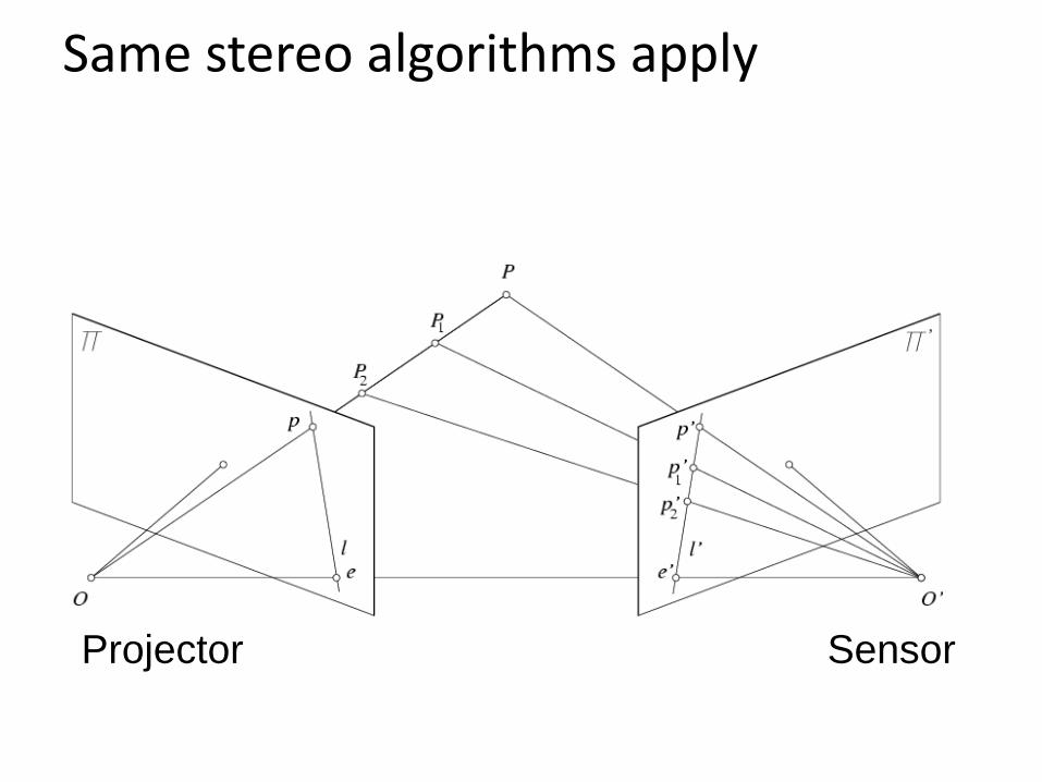
Same stereo algorithms apply
Projector Sensor

Example: Book vs. No Book Source: http://www.futurepicture.org/?p=97

Example: Book vs. No Book Source: http://www.futurepicture.org/?p=97
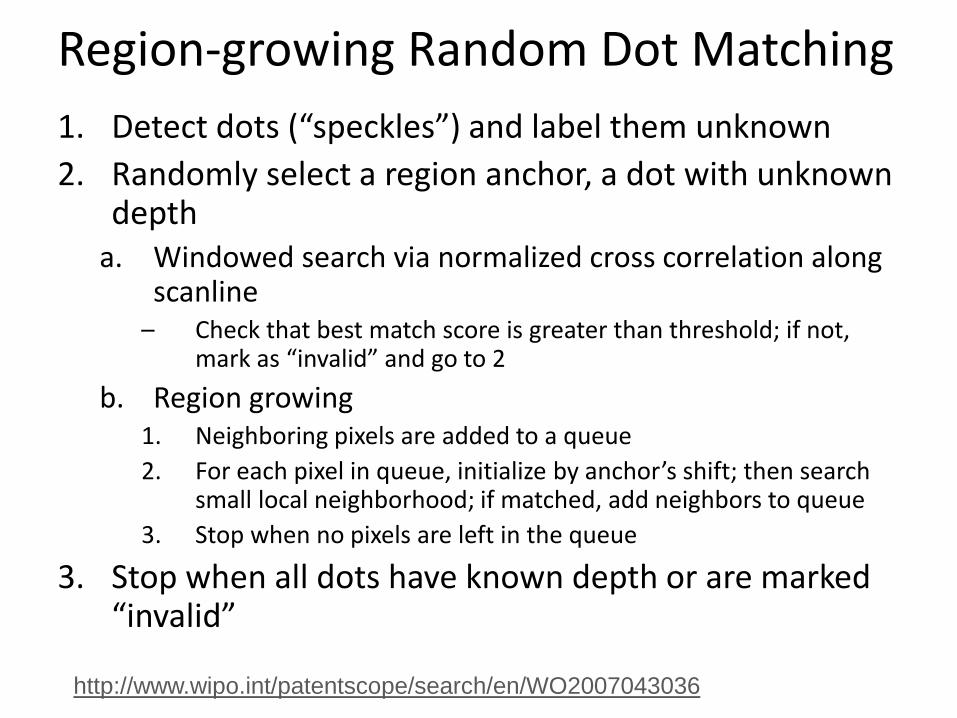
Region-growing Random Dot Matching
1. Detect dots (“speckles”) and label them unknown
2. Randomly select a region anchor, a dot with unknown depth
a. Windowed search via normalized cross correlation along scanline
– Check that best match score is greater than threshold; if not, mark as “invalid” and go to 2
b. Region growing 1. Neighboring pixels are added to a queue
2. For each pixel in queue, initialize by anchor’s shift; then search small local neighborhood; if matched, add neighbors to queue
3. Stop when no pixels are left in the queue
3. Stop when all dots have known depth or are marked “invalid”
http://www.wipo.int/patentscope/search/en/WO2007043036

Projected IR vs. Natural Light Stereo
• What are the advantages of IR?
– Works in low light conditions – Does not rely on having textured objects – Not confused by repeated scene textures – Can tailor algorithm to produced pattern
• What are advantages of natural light?
– Works outside, anywhere with sufficient light – Uses less energy – Resolution limited only by sensors, not projector
• Difficulties with both – Very dark surfaces may not reflect enough light – Specular reflection in mirrors or metal causes trouble

Part 2: Pose from depth
IR Projector
IR Sensor Projected Light Pattern
Depth Image
Stereo
Algorithm
Segmentation,
Part Prediction
Body Pose
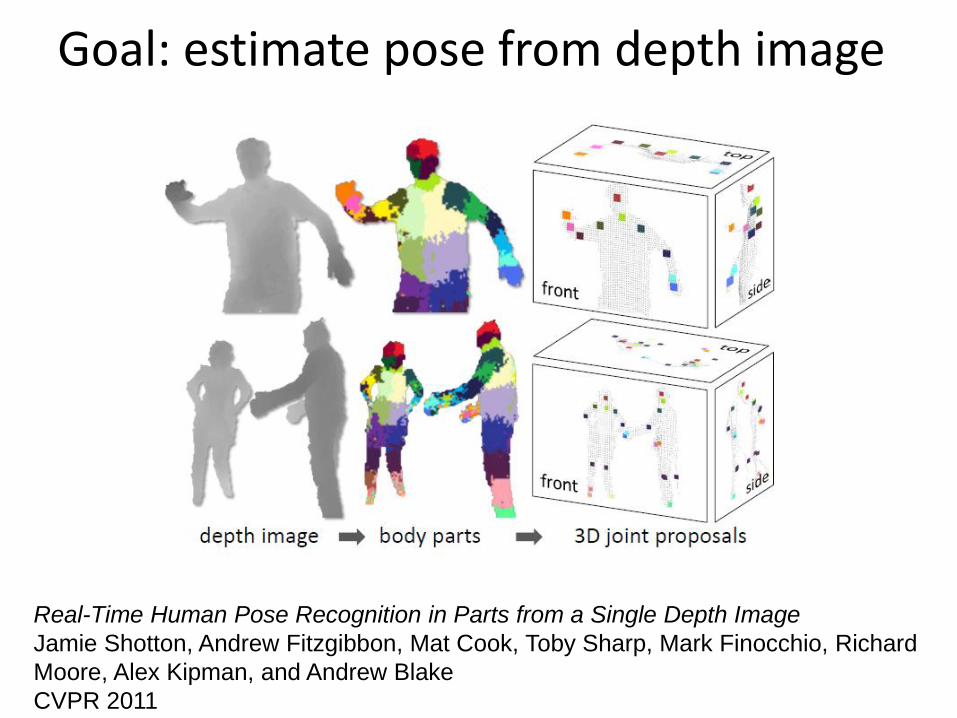
Goal: estimate pose from depth image
Real-Time Human Pose Recognition in Parts from a Single Depth Image
Jamie Shotton, Andrew Fitzgibbon, Mat Cook, Toby Sharp, Mark Finocchio, Richard
Moore, Alex Kipman, and Andrew Blake
CVPR 2011

Goal: estimate pose from depth image
RGB Depth Part Label Map Joint Positions
http://research.microsoft.com/apps/video/d
efault.aspx?id=144455
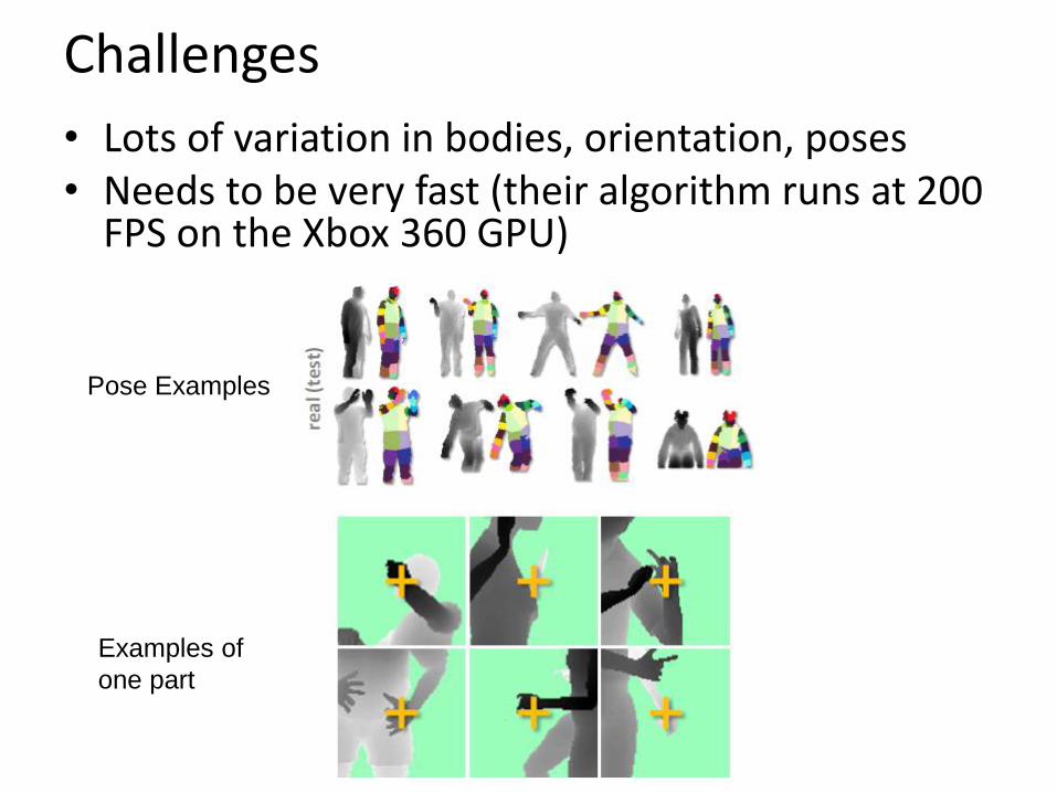
Challenges
• Lots of variation in bodies, orientation, poses • Needs to be very fast (their algorithm runs at 200
FPS on the Xbox 360 GPU)
Pose Examples
Examples of
one part

Extract body pixels by thresholding depth

Basic learning approach
• Very simple features
• Lots of data
• Flexible classifier

Get lots of training data
• Capture and sample 500K mocap frames of people kicking, driving, dancing, etc.
• Get 3D models for 15 bodies with a variety of weight, height, etc.
• Synthesize mocap data for all 15 body types
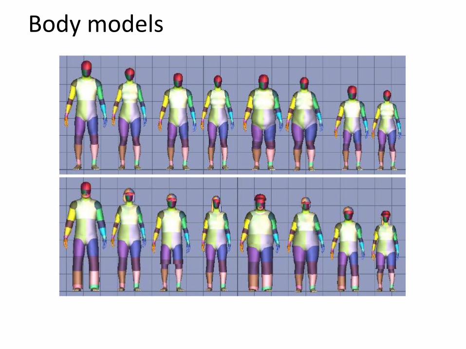
Body models

Features
• Difference of depth at two offsets
– Offset is scaled by depth at center

Part prediction with random forests
• Randomized decision forests: collection of independently trained trees
• Each tree is a classifier that predicts the likelihood of a pixel belonging to each part – Node corresponds to a thresholded feature – The leaf node that an example falls into corresponds to a
conjunction of several features – In training, at each node, a subset of features is chosen
randomly, and the most discriminative is selected

Joint estimation
• Joints are estimated using mean-shift (a fast mode-finding algorithm)
• Observed part center is offset by pre-estimated value
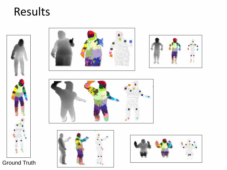
Results
Ground Truth
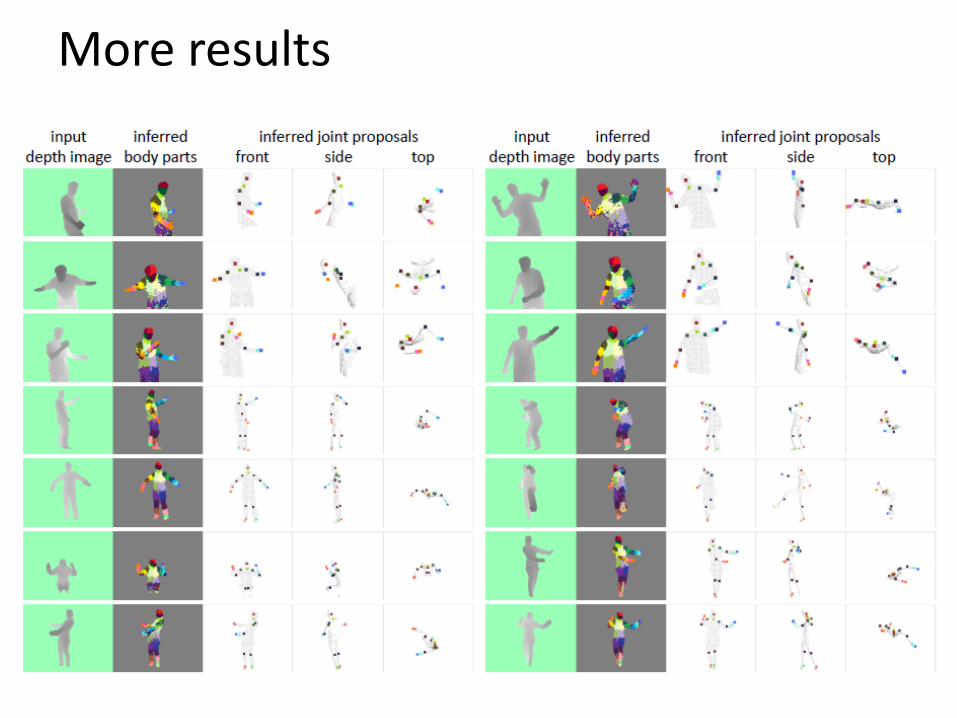
More results

Accuracy vs. Number of Training Examples
Uses of Kinect
• Mario: http://www.youtube.com/watch?v=8CTJL5lUjHg
• Robot Control: http://www.youtube.com/watch?v=w8BmgtMKFbY
• Capture for holography: http://www.youtube.com/watch?v=4LW8wgmfpTE
• Virtual dressing room: http://www.youtube.com/watch?v=1jbvnk1T4vQ
• Fly wall: http://vimeo.com/user3445108/kiwibankinteractivewall
• 3D Scanner: http://www.youtube.com/watch?v=V7LthXRoESw

To learn more
• Warning: lots of wrong info on web
• Great site by Daniel Reetz: http://www.futurepicture.org/?p=97
• Kinect patents: http://www.faqs.org/patents/app/20100118123 http://www.faqs.org/patents/app/20100020078 http://www.faqs.org/patents/app/20100007717

Next week
• Tues
– ICES forms (important!) – Wrap-up, proj 5 results
• Normal office hours + feel free to stop by other times on
Tues, Thurs – Try to stop by instead of e-mail except for one-line answer kind
of things
• Final project reports due Thursday at midnight
• Friday
– Final project presentations at 1:30pm – If you’re in a jam for final project, let me know early