lecture 27 controlled rectifiers dr. rostamkolai ece 452 power electronics 1
TRANSCRIPT

LECTURE 27 Controlled Rectifiers
Dr. Rostamkolai
ECE 452Power Electronics
1

Single-Phase Series Converters
For high voltage applications, two or more converters can be connected in series to share the voltage and also to improve the power factor
The following figure shows two semiconverters that are connected in series
Each transformer secondary has the same number of turns, and the turns ratio is 2
2

3

4

Twelve-Pulse Converter
For high-power applications such as high-voltage dc transmission, a 12-pulse output is generally required to reduce the output ripples and to increase the ripple frequencies
Two six-pulse bridges can be combined either in series or in parallel to produce a 12-pulse output
Two configurations are shown in the following figure
5

6

A 30 degrees phase shift between secondary windings can be accomplished by connecting one secondary in wye and the other in delta
7

Design of Converter Circuits
The design of converter circuits requires determining the ratings of switching devices and diodes
The switches and diodes are specified by: Average current RMS current Peak current Peak inverse voltage 8

In case of the controlled rectifiers, the current rating of devices depend on the delay angle
The ratings of power devices must be designed under the worst case condition
This occurs when the converter delivers the maximum average output voltage 9

The output of converters contain harmonics that depend on the delay angle
The worst-case condition is generally when the minimum output voltage occurs
Input and output filters must be designed under the minimum output voltage conditions 10

Effect of Load and Source Inductances
The load current harmonics depend on load inductances
Also, the input power factor depends on the load power factor
So far, in derivations of output voltages and the performance criteria of converters, we have assumed that the source has no inductances and resistances
11
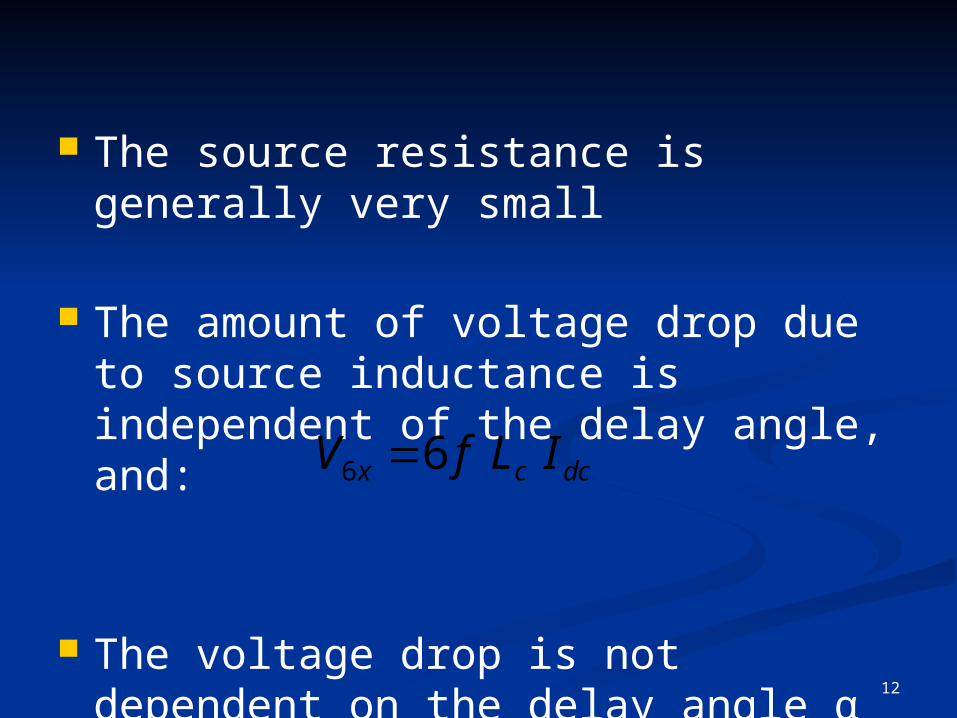
The source resistance is generally very small
The amount of voltage drop due to source inductance is independent of the delay angle, and:
The voltage drop is not dependent on the delay angle α
dccx ILfV 66
12

However, the commutation (overlap) angle μ varies with the delay angle
As the delay angle increases, the overlap angle decreases
13

14

If Vx is the average voltage drop per commutation due to overlap and Vy is the average voltage reduction due to phase angle control that is zero, then average output voltage is (when ignoring commutation overlap):
ydmdc
ydcdc
VVV
VVV
)0(
max
15

The average output voltage with overlap due to two commutations and phase angle control is:
xdcdc
xydmdc
yxdcdc
VVV
VVVV
VVVV
2)()(
2)(
2)0()(
16

Then:
The overlap angle μ can be determined from the above equation for a single-phase full converter
)()(22
2)()(
dcdccdcx
xdcdc
VVLIfV
VVV
17

Work on Example 10.10
α = 10o → µ = 4.66o
α = 30o → µ = 1.94o
α = 60o → µ = 1.14o
18