lecture 27 counters. overview °counters are important components in computers the increment or...
TRANSCRIPT

Lecture 27
Counters

Overview
° Counters are important components in computers• The increment or decrement by one in response to input
° Counters with D Flip Flops
° Counters with JK and T Flip Flops
° Types of Counters• Ripple counters
• Flip flop output serves as a source for triggering other flip flops
° Synchronous counters• All flip flops triggered by a clock signal
° Synchronous counters are more widely used in industry.
Counters
° Counter: A register that goes through a prescribed series of states
° Binary counter• Counter that follows a binary sequence
• N bit binary counter counts in binary from n to 2n-1
° Ripple counters triggered by initial Count signal
° Applications:• Watches
• Clocks
• Alarms
• Web browser refresh
Counters
•In digital logic and computing, a counter is a device which stores (and sometimes displays) the number of times a particular event or process has occurred, often in relationship to a clock signal.
A counter is a "degenerate" finite state machine/sequential circuit where the state is the only outputA counter is a "degenerate" finite state machine/sequential circuit where the state is the only output
Proceed through a well-defined sequence of states in response to count signal
3 Bit Up-counter: 000, 001, 010, 011, 100, 101, 110, 111, 000, ...
3 Bit Down-counter: 111, 110, 101, 100, 011, 010, 001, 000, 111, ...
Binary vs. BCD vs. Gray Code Counters
Electronic counters
•In electronics, counters can be implemented quite easily using register-type circuits such as the flip-flop, and a wide variety of classifications exist:
1. Asynchronous (ripple) counter – changing state bits are used as clocks to subsequent state flip-flops
2. Synchronous counter – all state bits change under control of a single clock
3. Decade counter – counts through ten states per stage
Electronic counters(continued)
4. Up/down counter – counts both up and down, under command of a control input
5. Ring counter – formed by a shift register with feedback connection in a ring
6. Johnson counter – a twisted ring counter
7. Cascaded counter


Counter Design Procedure
Counter Design Procedure
Counter Design Procedure
Example Continued

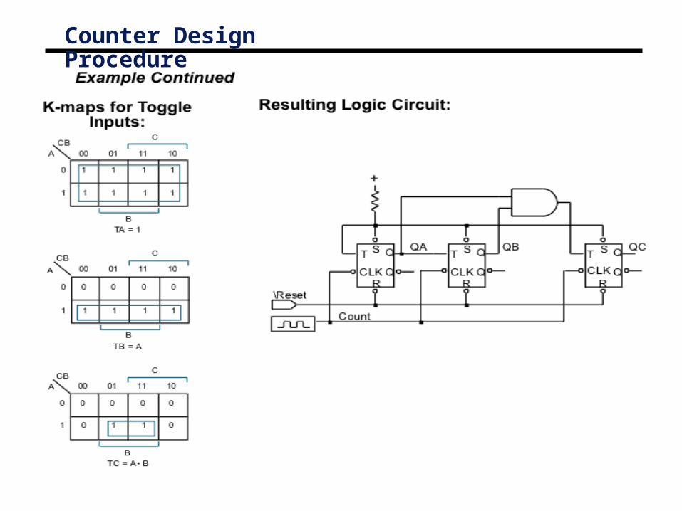
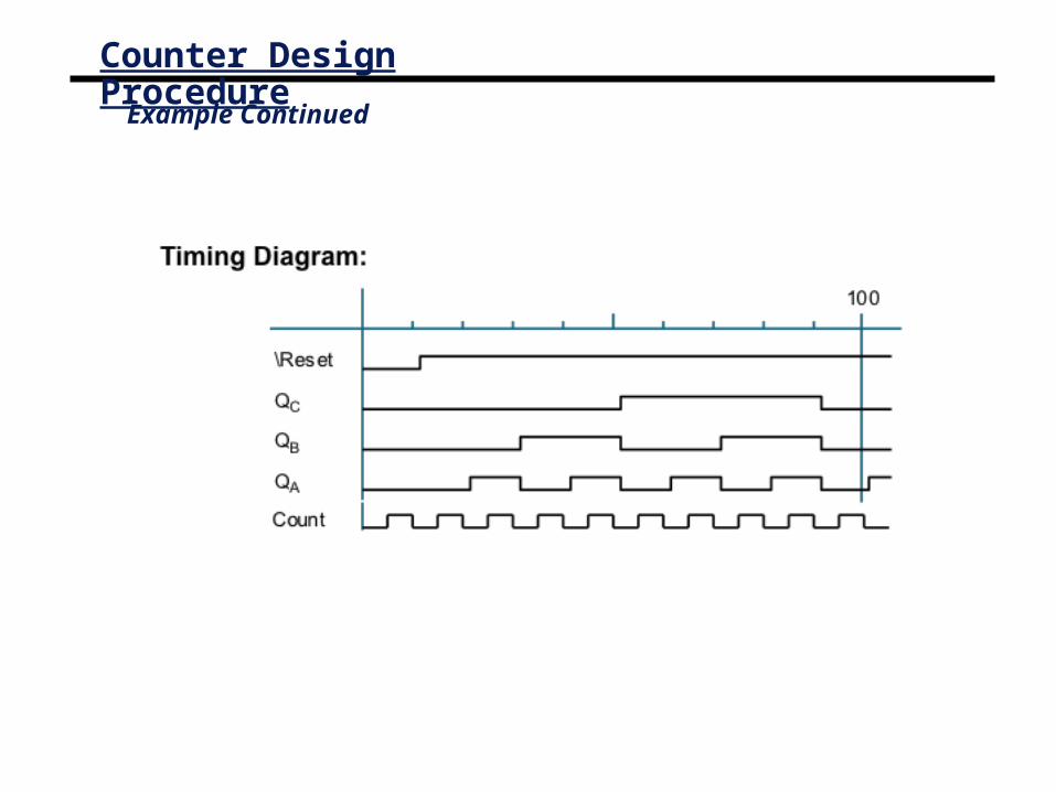
Counter Design Procedure
Example ContinuedK-maps for Toggle
Inputs:
Resulting Logic Circuit:
T
CLK
\Reset
Q
Q
S
R
QAT
CLK
Q
Q
S
R
QBT
CLK
Q
Q
S
R
QC
Count
+
TB = A
TC = A • B
T A = 1
CB A
C
00 01 11 10
0
1
B
1 1 1 1
1 1 1 1
CB
A
C
00 01 11 10
0
1
B
0 0 0 0
1 1 1 1
CB A
C
B
00 01 11 10
0
1
0 0 0 0
0 1 1 0

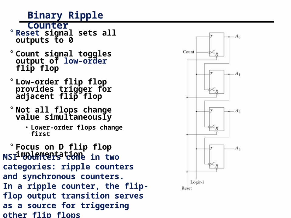
Binary Ripple Counter
° Reset signal sets all outputs to 0
° Count signal toggles output of low-order flip flop
° Low-order flip flop provides trigger for adjacent flip flop
° Not all flops change value simultaneously
• Lower-order flops change first
° Focus on D flip flop implementation
MSI counters come in two categories: ripple counters and synchronous counters. In a ripple counter, the flip-flop output transition serves as a source for triggering other flip flops

Another Asynchronous Ripple Counter
° Similar to T flop example on previous slide
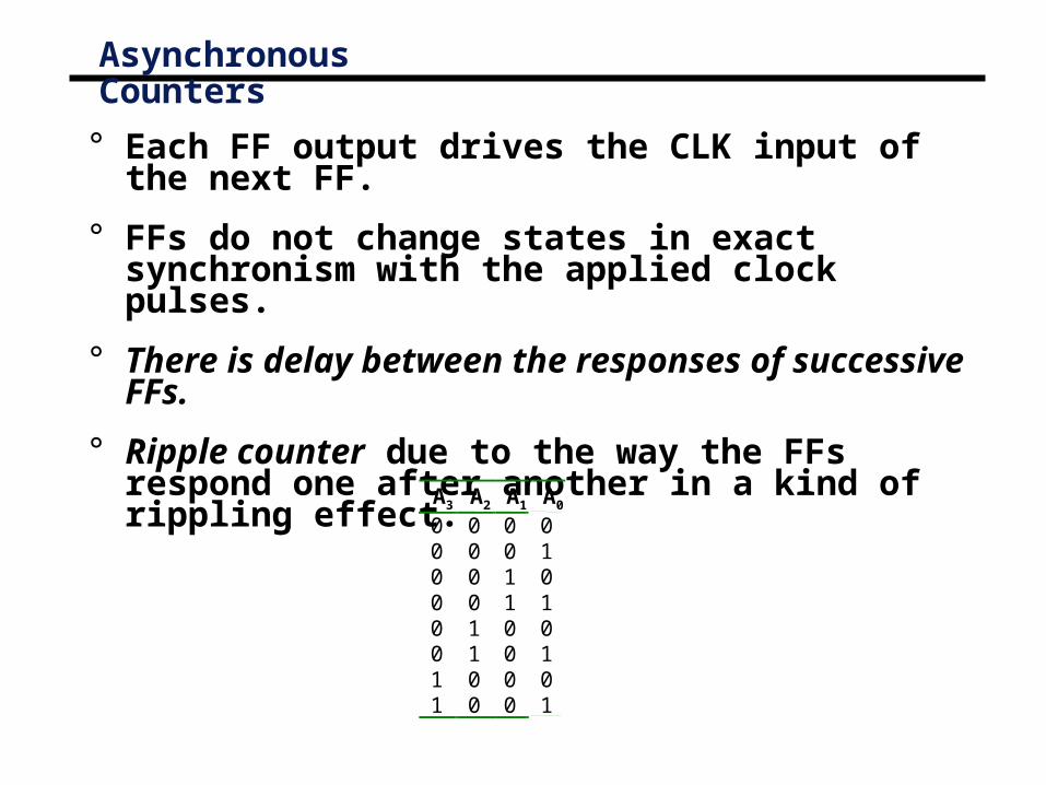
Asynchronous Counters
° Each FF output drives the CLK input of the next FF.
° FFs do not change states in exact synchronism with the applied clock pulses.
° There is delay between the responses of successive FFs.
° Ripple counter due to the way the FFs respond one after another in a kind of rippling effect.
A3 A20 00 00 00 00 10 11 01 0
A100110000
A001010101

Decade Decimal BCD Counter
Three-decade decimal BCD counter
A decade counter, since it counts from 0 to 9. Tocount in decimal from 0 to 99, we need a two-decade counter. And To count from 0 to 999

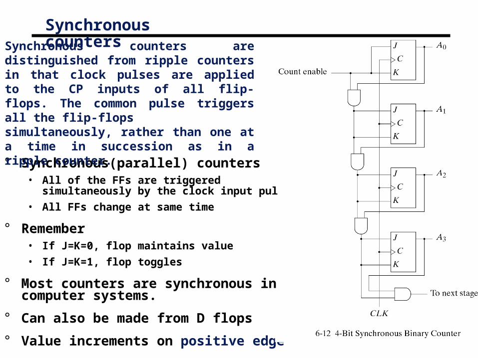
Synchronous counters
° Synchronous(parallel) counters• All of the FFs are triggered simultaneously by the
clock input pulses.
• All FFs change at same time
° Remember• If J=K=0, flop maintains value
• If J=K=1, flop toggles
° Most counters are synchronous in computer systems.
° Can also be made from D flops
° Value increments on positive edge
Synchronous counters are distinguished from ripple counters in that clock pulses are applied to the CP inputs of all flip-flops. The common pulse triggers all the flip-flopssimultaneously, rather than one at a time in succession as in a ripple counter.

Synchronous counters
° Synchronous counters• Same counter as previous slide except Count enable replaced
by J=K=1
• Note that clock signal is a square wave
• Clock fans out to all clock inputs

Circuit operation
° Count value increments on each negative edge
° Note that low-order bit (A) toggles on each clock cycle

Synchronous UP/Down counters
° Up/Down Counter can either count up or down on each clock cycle
° Up counter counts from 0000 to 1111 and then changes back to 0000
° Down counter counts from 1111 to 0000 and then back to 1111
° Counter counts up or down each clock cycle
° Output changes occur on clock rising edge
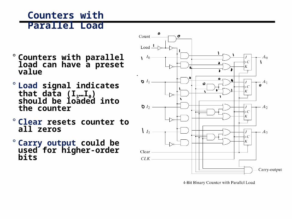
Counters with Parallel Load
° Counters with parallel load can have a preset value
° Load signal indicates that data (I3…I0) should be loaded into the counter
° Clear resets counter to all zeros
° Carry output could be used for higher-order bits

Counters with Parallel Load
Clear Clk Load Count Function 0 X X X Clear to 0 1 ↑ 1 X Load inputs 1 ↑ 0 1 Count 1 ↑ 0 0 No Change
Function Table
° If Clear is asserted (0), the counter is cleared
° If Load is asserted data inputs are loaded
° If Count asserted counter value is incremented

Binary Counter with Parallel Load and Preset• Presettable parallel counter with
asynchronous preset.
If PL’ = 0, load P into flops

Binary Counter with Parallel Load and Preset
• Commercial version of binary counter


° D0 = Q0 XOR Enable
° D1 = Q1 XOR Q0 & Enable
° D2 = Q2 XOR Q1 & Q0 & Enable
° D3 = Q3 XOR Q2 & Q1 & Q0 & Enable
4 Bit Binary Counter with D Flip Flops
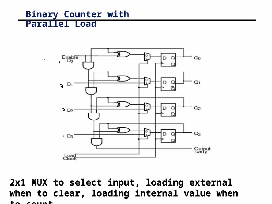
2x1 MUX to select input, loading external when to clear, loading internal value when to count.
Binary Counter with Parallel Load
BCD
°In computing and electronic systems, binary-coded decimal (BCD) (sometimes called natural binary-coded decimal, NBCD) or, in its most common modern implementation, packed decimal, is an encoding for decimal numbers in which each digit is represented by its own binary sequence. Its main virtue is that it allows easy conversion to decimal digits for printing or display, and allows faster decimal calculations. Its drawbacks are a small increase in the complexity of circuits needed to implement mathematical operations. Uncompressed BCD is also a relatively inefficient encoding—it occupies more space than a purely binary representation.
°In BCD, a digit is usually represented by four bits which, in general, represent the decimal digits 0 through 9. Other bit combinations are sometimes used for a sign or for other indications (e.g., error or overflow).
°Although uncompressed BCD is not as widely used as it once was, decimal fixed-point and floating-point are still important and continue to be used in financial, commercial, and industrial computing.

BCD: 0000 0001 0010 0011 0100 0101 0110 0111 1000 1001
Basics for BCD
•To encode a decimal number using the common BCD encoding, each decimal digit is stored in a 4-bit nibble:
•Decimal: 0 1 2 3 4 5 6 7 8 9
•Thus, the BCD encoding for the number 127 would be:
0001 0010 0111
•Whereas the pure binary number would be:
0111 1111

Binary-coded-decimal(BCD) counters

• Consists of two modulo-10 counters, one for each BCD digit.
• It is necessary to reset the four flip-flops after the count of 9 has been obtained. Thus the Load input to each stage is equal to 1 when Q3=Q0=1, which causes 0s to be loaded into the flip-flops at the next positive edge of the clock signal.
• Keeping the Enable signal for BCD1 low at all times except when BCD0 = 9
IBM and BCD
•IBM used the terms binary-coded decimal and BCD for 6-bit alphamerics codes that represented numbers, upper-case letters and special characters. Some variation of BCD alphamerics was used in most early IBM computers, including the IBM 1620, IBM 1400 series, and non-Decimal Architecture members of the IBM 700/7000 series.
•Today, BCD data is still heavily used in IBM processors and databases, such as IBM DB2, mainframes, and Power6. In these products, the BCD is usually zoned BCD (as in EBCDIC or ASCII), Packed BCD (two decimal digits per byte), or "pure" BCD encoding (one decimal digit stored as BCD in the low four bits of each byte). All of these are used within hardware registers and processing units, and in software.
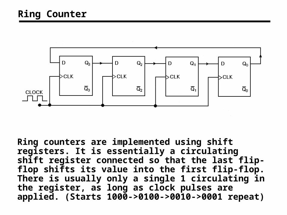
Ring counters are implemented using shift registers. It is essentially a circulating shift register connected so that the last flip-flop shifts its value into the first flip-flop. There is usually only a single 1 circulating in the register, as long as clock pulses are applied. (Starts 1000->0100->0010->0001 repeat)
Ring Counter

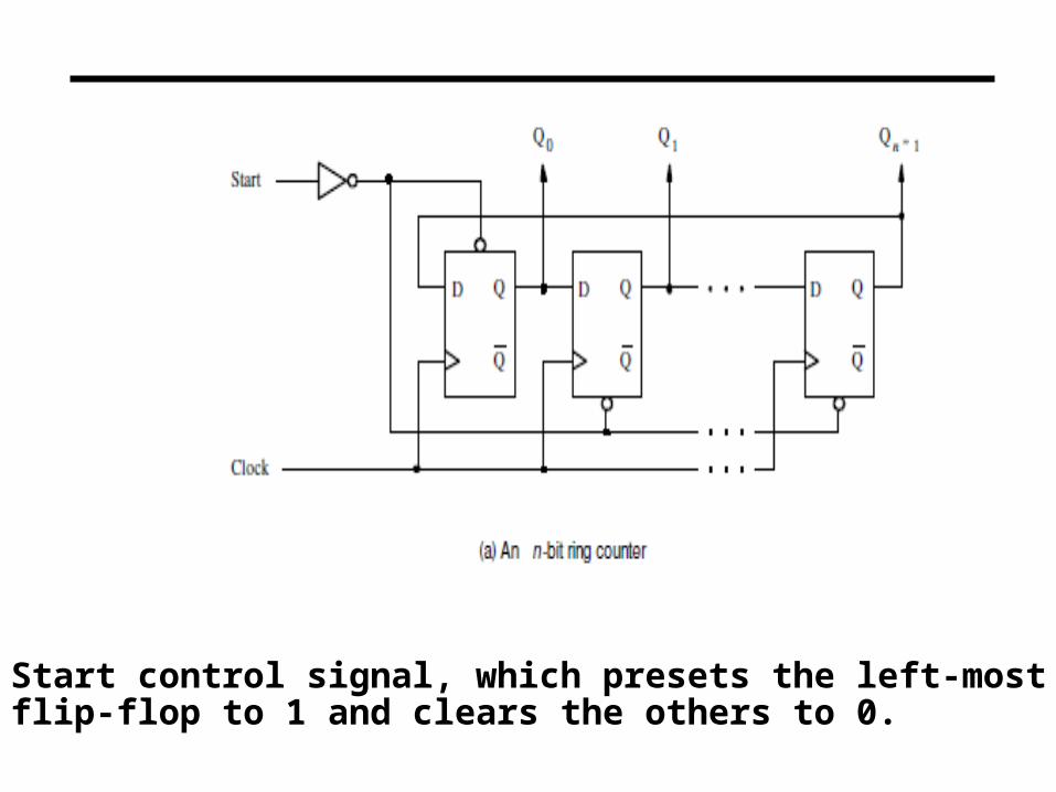
Start control signal, which presets the left-most flip-flop to 1 and clears the others to 0.

Johnson Counter
The Johnson counter, also known as the twisted-ring counter, is exactly the same as the ring counter except that the inverted output of the last flip-flop is connected to the input of the first flip-flop. Let’s say, starts from 000, 100, 110, 111, 011 and 001, and the sequence is repeated so long as there is input pulse.
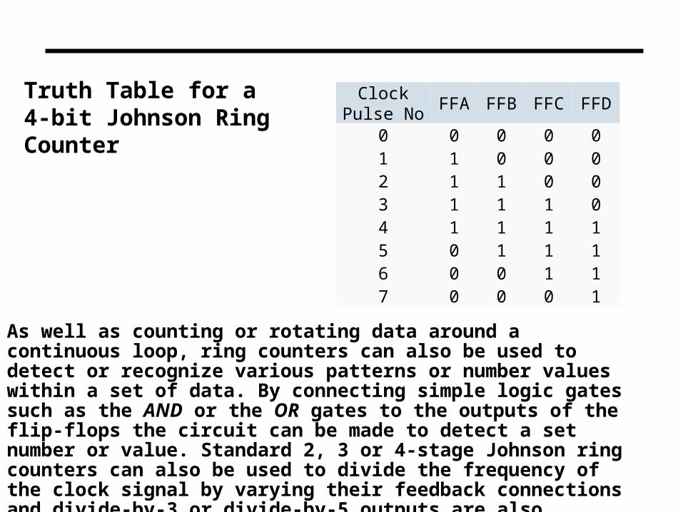
As well as counting or rotating data around a continuous loop, ring counters can also be used to detect or recognize various patterns or number values within a set of data. By connecting simple logic gates such as the AND or the OR gates to the outputs of the flip-flops the circuit can be made to detect a set number or value. Standard 2, 3 or 4-stage Johnson ring counters can also be used to divide the frequency of the clock signal by varying their feedback connections and divide-by-3 or divide-by-5 outputs are also available.
Clock Pulse No
FFA FFB FFC FFD
0 0 0 0 01 1 0 0 02 1 1 0 03 1 1 1 04 1 1 1 15 0 1 1 16 0 0 1 17 0 0 0 1
Truth Table for a 4-bit Johnson Ring Counter

To initialize the operation of the Johnson counter, it is necessary to reset all flip-flops, as shown in the figure. Observe that neither the Johnson nor the ring counter will generate the desired counting sequence if not initialized properly.


Summary
° Binary counters can be ripple or synchronous
° Ripple counters use flip flop outputs as flop triggers• Some delay before all flops settle on a final value
• Do no require a clock signal
° Synchronous counters are controlled by a clock• All flip flops change at the same time
° Up/Down counters can either increment or decrement a stored binary value
• Control signal determines if counter counts up or down
° Counters with parallel load can be set to a known value before counting begins.
° D, T and J/K Flip Flops can be used for counter design