lecture 3.4 temperature and light sensors - lunyax's blog · pdf fileand generates an...
TRANSCRIPT
Temperature and light sensors
principle of working of some of the temperature sensors are discussed in following sections. 1. Bimetallic strips
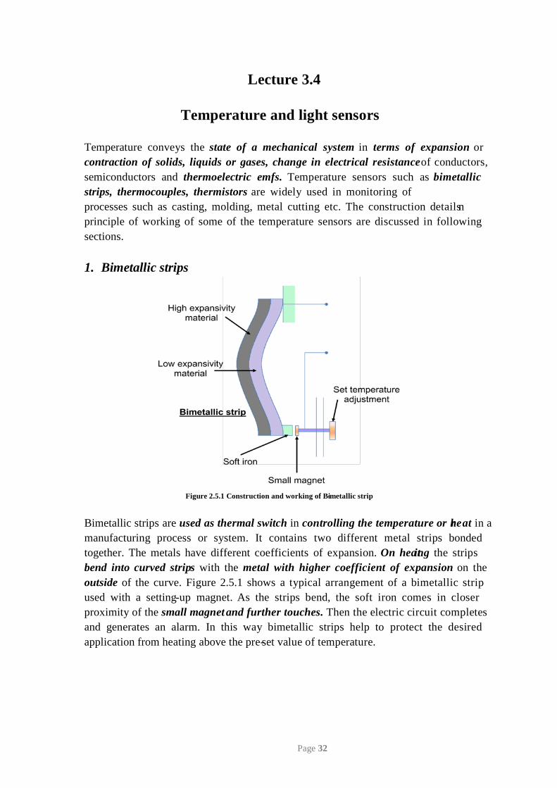
Figure 2.5.1 Construction and working of Bi-metallic strip
manufacturing process or system. It contains two different metal strips bonded
used with a setting-up magnet. As the strips bend, the soft iron comes in closer
and generates an alarm. In this way bimetallic strips help to protect the desired application from heating above the pre-set value of temperature.
Lecture 3.4
Page 32
Temperature conveys the state of a mechanical system in terms of expansion or contraction of solids, liquids or gases, change in electrical resistance of conductors, semiconductors and thermoelectric emfs. Temperature sensors such as bimetallic strips, thermocouples, thermistors are widely used in monitoring of processes such as casting, molding, metal cutting etc. The construction detailsn
Bimetallic strips are used as thermal switch in controlling the temperature or her at in a
together. The metals have different coefficients of expansion. On heaint g the strips bend into curved strips with the metal with higher coefficient of expansion on the outside of the curve. Figure 2.5.1 shows a typical arrangement of a bimetallic strip
proximity of the small magnet and further touches. Then the electric circuit completes

2. Resistance temperature detectors (RTDs)
a linear relationship as shown in Figure 2.5.2. The correlation is
t 0
where Rt is the resistance at temperature T (⁰C) and R0 is the temperature at 0⁰C and α
sensor is usually made to have a resistance of 100 Ω at 0 °C
Figure 2.5.2 Behavior of RTD materials [1]
Figure 2.5.3 Construction of a Resistance temperature detector (RTD)
Figure 2.5.3 shows the construction of a RTD. It has a resistor element connected to a Wheatstone bridge. The element and the connection leads are insulated and protected by a sheath. A small amount of current is continuously passing though the coil. As the
Wheatstone bridge.
Page 33
RTDs work on the principle that the electric resistance of a metal changes due to change in its temperature. On heating up metals, their resistance increases and follows
= R (1 + αT) (2.5.1) R
is the constant for the metal termed as temperature coefficient of resistance. The
temperature changes the resistance of the coil changes which is detected at the
RTDs are used in the form of thin films, wire wound or coil. They are generally made of metals such as platinum, nickel or nickel-copper alloys. Platinum wire held by a high-temperature glass adhesive in a ceramic tube is used to measure the temperature in a metal furnace. Other applications are:
• Air conditioning and refrigeration servicing • Food Processing • Stoves and grills • Textile production • Plastics processing • Petrochemical processing • Micro electronics • Air, gas and liquid temperature measurement in pipes and tanks • Exhaust gas temperature measurement
3. Thermistors
such as a sintered metal oxide (mixtures of metal oxides, chromium, cobalt, iron, manganese and nickel) or doped polycrystalline ceramic containing barium titanate
dimensions. They exhibit nonlinear response characteristics.
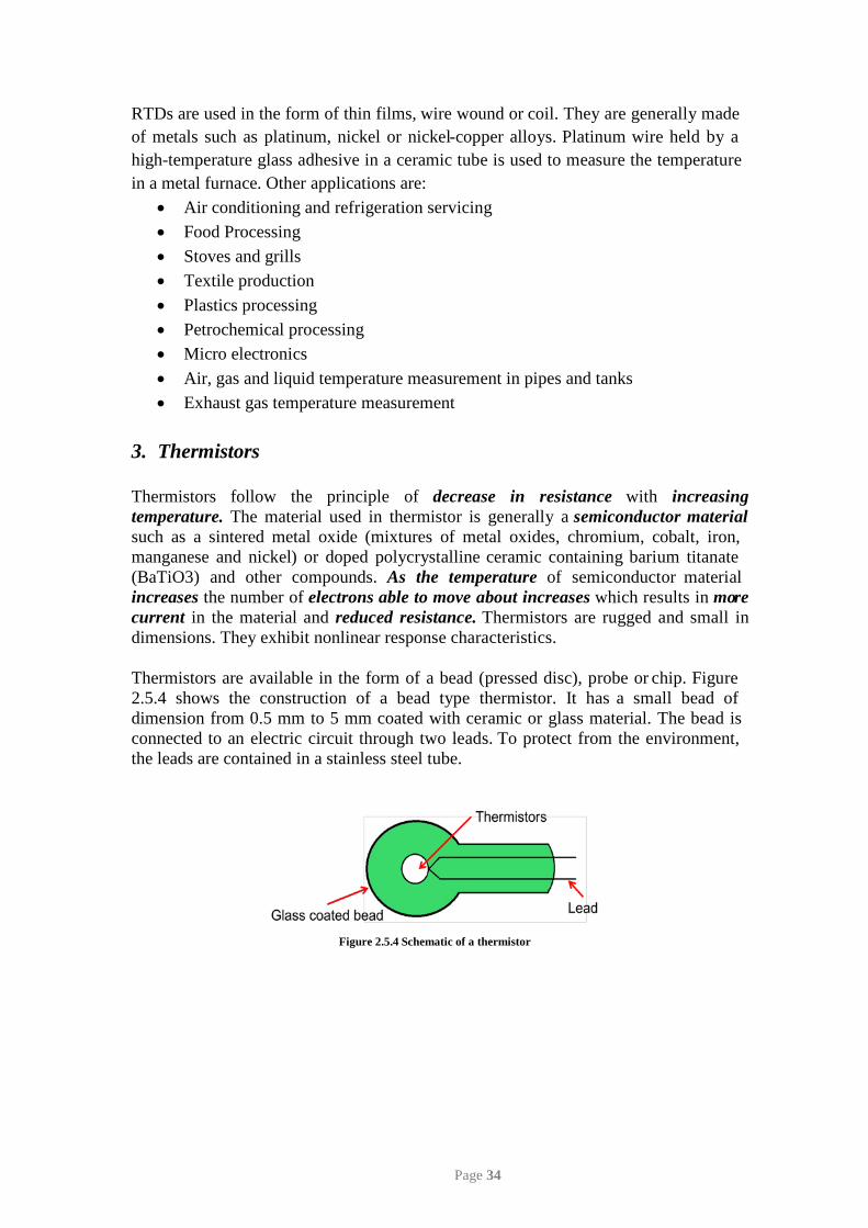
Thermistors are available in the form of a bead (pressed disc), probe or chip. Figure 2.5.4 shows the construction of a bead type thermistor. It has a small bead of dimension from 0.5 mm to 5 mm coated with ceramic or glass material. The bead is connected to an electric circuit through two leads. To protect from the environment, the leads are contained in a stainless steel tube.
Figure 2.5.4 Schematic of a thermistor
Page 34
Thermistors follow the principle of decrease in resistance with increasing temperature. The material used in thermistor is generally a semiconductor material
(BaTiO3) and other compounds. As the temperature of semiconductor material increases the number of electrons able to move about increases which results in more current in the material and reduced resistance. Thermistors are rugged and small in
Applications of Thermistors
• To monitor the coolant temperature and/or oil temperature inside the engine • To monitor the temperature of an incubator • Thermistors are used in modern digital thermostats • To monitor the temperature of battery packs while charging • To monitor temperature of hot ends of 3D printers • To maintain correct temperature in the food handling and processing industry
equipments • To control the operations of consumer appliances such as toasters, coffee
makers, refrigerators, freezers, hair dryers, etc.
4. Thermocouple
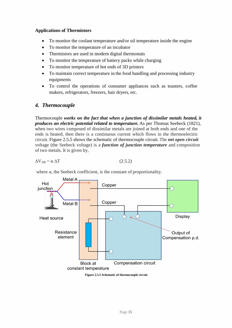
when two wires composed of dissimilar metals are joined at both ends and one of the ends is heated, then there is a continuous current which flows in the thermoelectric
of two metals. It is given by, ∆VAB = α ∆T (2.5.2) where α, the Seebeck coefficient, is the constant of proportionality.
Figure 2.5.5 Schematic of thermocouple circuit
Page 35
produces an electric potential related to temperature. As per Thomas Seebeck (1821), Thermocouple works on the fact that when a junction of dissimilar metals heated, it
circuit. Figure 2.5.5 shows the schematic of thermocouple circuit. The net open circuit voltage (the Seebeck voltage) is a function of junction temperature and composition
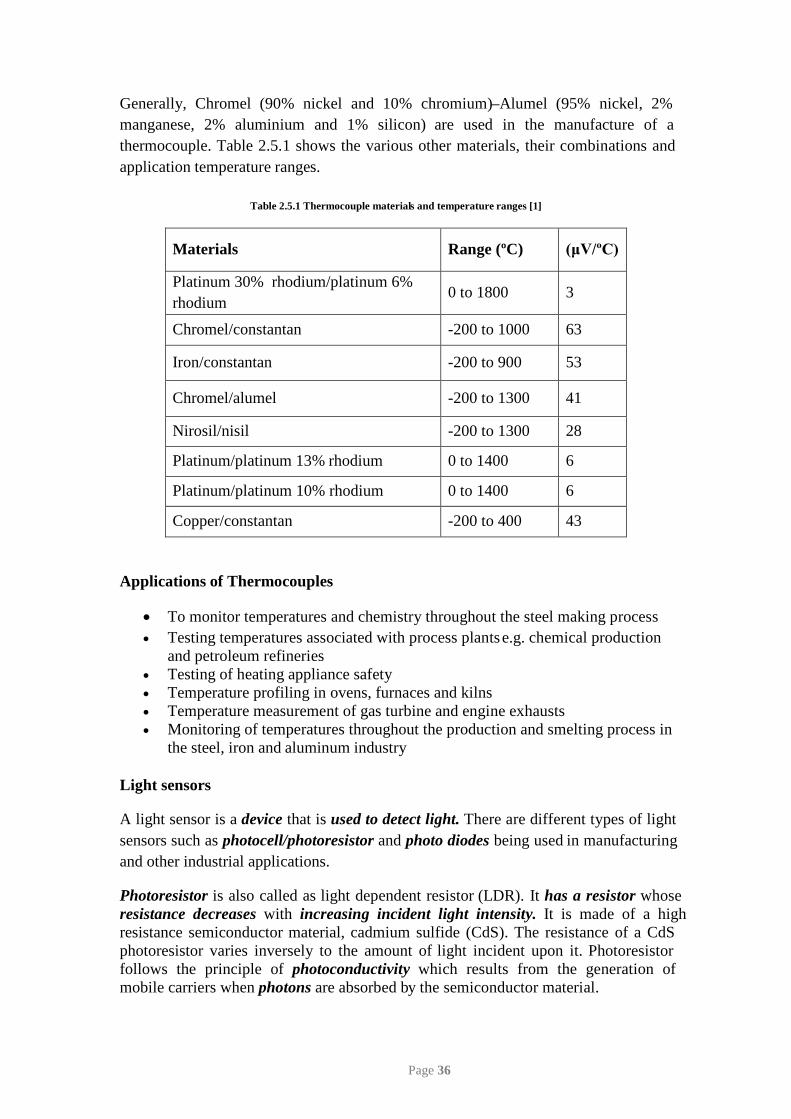
Generally, Chromel (90% nickel and 10% chromium)–Alumel (95% nickel, 2% manganese, 2% aluminium and 1% silicon) are used in the manufacture of a thermocouple. Table 2.5.1 shows the various other materials, their combinations and application temperature ranges.
Table 2.5.1 Thermocouple materials and temperature ranges [1]
Materials Range (ºC) (μV/ºC)
Platinum 30% rhodium/platinum 6% rhodium
0 to 1800 3
Chromel/constantan -200 to 1000 63
Iron/constantan -200 to 900 53
Chromel/alumel -200 to 1300 41
Nirosil/nisil -200 to 1300 28
Platinum/platinum 13% rhodium 0 to 1400 6
Platinum/platinum 10% rhodium 0 to 1400 6
Copper/constantan -200 to 400 43
Applications of Thermocouples
• To monitor temperatures and chemistry throughout the steel making process • Testing temperatures associated with process plants e.g. chemical production
and petroleum refineries • Testing of heating appliance safety • Temperature profiling in ovens, furnaces and kilns • Temperature measurement of gas turbine and engine exhausts • Monitoring of temperatures throughout the production and smelting process in
the steel, iron and aluminum industry
Light sensors
and other industrial applications.
resistance semiconductor material, cadmium sulfide (CdS). The resistance of a CdS photoresistor varies inversely to the amount of light incident upon it. Photoresistor
Page 36
sensors such as photocell/photoresistor and photo diodes being used in manufacturing
Photoresistor is also called as light dependent resistor (LDR). It has a resistor whose resistance decreases with increasing incident light intensity. It is made of a high
follows the principle of photoconductivity which results from the generation of mobile carriers when photons are absorbed by the semiconductor material.
A light sensor is a device that is used to detect light. There are different types of light
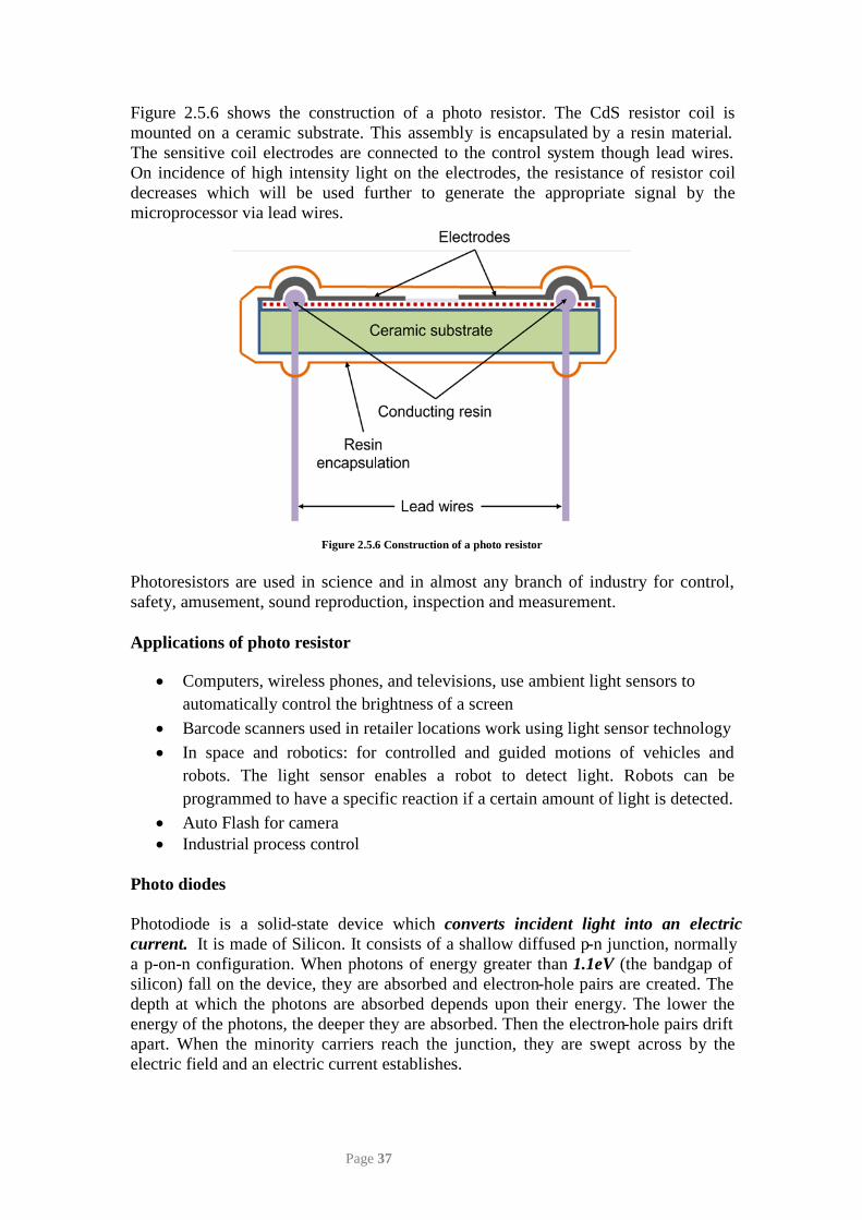
Figure 2.5.6 shows the construction of a photo resistor. The CdS resistor coil is mounted on a ceramic substrate. This assembly is encapsulated by a resin material. The sensitive coil electrodes are connected to the control system though lead wires. On incidence of high intensity light on the electrodes, the resistance of resistor coil decreases which will be used further to generate the appropriate signal by the microprocessor via lead wires.
Figure 2.5.6 Construction of a photo resistor
Photoresistors are used in science and in almost any branch of industry for control, safety, amusement, sound reproduction, inspection and measurement.
Applications of photo resistor
• Computers, wireless phones, and televisions, use ambient light sensors to automatically control the brightness of a screen
• Barcode scanners used in retailer locations work using light sensor technology • In space and robotics: for controlled and guided motions of vehicles and
robots. The light sensor enables a robot to detect light. Robots can be programmed to have a specific reaction if a certain amount of light is detected.
• Auto Flash for camera • Industrial process control
Photo diodes
silicon) fall on the device, they are absorbed and electron-hole pairs are created. The depth at which the photons are absorbed depends upon their energy. The lower the energy of the photons, the deeper they are absorbed. Then the electron-hole pairs drift apart. When the minority carriers reach the junction, they are swept across by the electric field and an electric current establishes.
Page 37
Photodiode is a solid-state device which converts incident light into an electric current. It is made of Silicon. It consists of a shallow diffused p-n junction, normally a p-on-n configuration. When photons of energy greater than 1.1eV (the bandgap of
fiber connection to allow light to reach the sensitive part of the device.
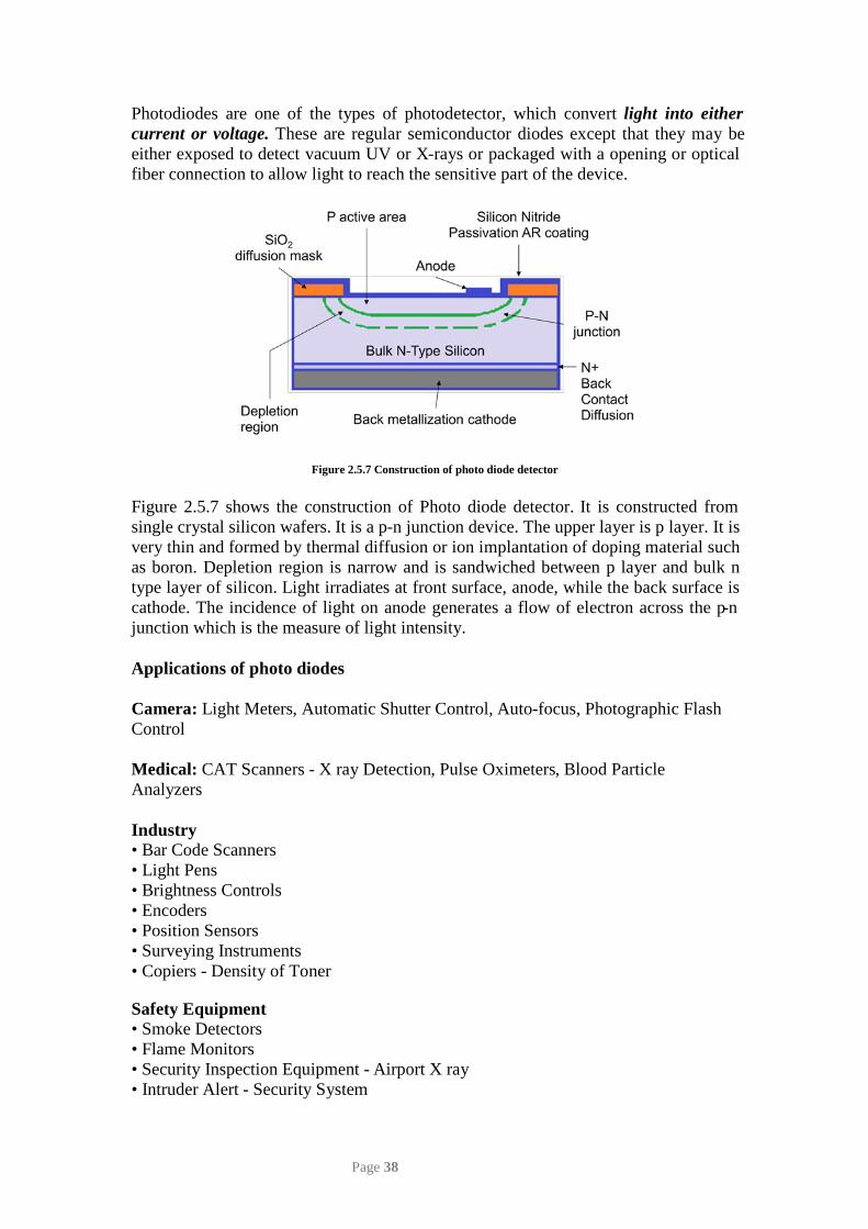
Figure 2.5.7 Construction of photo diode detector
Figure 2.5.7 shows the construction of Photo diode detector. It is constructed from single crystal silicon wafers. It is a p-n junction device. The upper layer is p layer. It is very thin and formed by thermal diffusion or ion implantation of doping material such as boron. Depletion region is narrow and is sandwiched between p layer and bulk n type layer of silicon. Light irradiates at front surface, anode, while the back surface is cathode. The incidence of light on anode generates a flow of electron across the p-n junction which is the measure of light intensity.
Applications of photo diodes
Camera: Light Meters, Automatic Shutter Control, Auto-focus, Photographic Flash Control Medical: CAT Scanners - X ray Detection, Pulse Oximeters, Blood Particle Analyzers Industry • Bar Code Scanners • Light Pens • Brightness Controls • Encoders • Position Sensors • Surveying Instruments • Copiers - Density of Toner
Safety Equipment • Smoke Detectors • Flame Monitors • Security Inspection Equipment - Airport X ray • Intruder Alert - Security System
Page 38
Photodiodes are one of the types of photodetector, which convert light into either
either exposed to detect vacuum UV or X-rays or packaged with a opening or optical current or voltage. These are regular semiconductor diodes except that they may be
Automotive • Headlight Dimmer • Twilight Detectors • Climate Control - Sunlight Detector Communications • Fiber Optic Links • Optical Communications • Optical Remote Control Quiz:
1. ‘In thermistor sensors, resistance decreases in a very nonlinear manner with increase in temperature.’ State true or false and justify.
2. List the various temperature sensors used by we in/around our home/office/university.
3. Develop a conceptual design of a Light sensors based control system for counting a number of milk packets being packed for discharge. Assume suitable data if necessary.
References
1. Boltan, W., Mechatronics: electronic control systems in mechanical and electrical engineering, Longman, Singapore, 1999.
Page 39