lecture 7: elements
TRANSCRIPT

Lecture 7:ELEMENTS
TECHSummer School at WUST, Steel Structures 22-23.07.2019
Dr Michal Redecki

ELEMENTSLecture 7.1 : Methods of Analysis of Steel StructuresLecture 7.2 : Cross-Section Classification
Lecture 7.3 : Local BucklingLecture 7.4.1 : Tension Members ILecture 7.4.2 : Tension Members II
Lecture 7.5.1 : Columns ILecture 7.5.2 : Columns IILecture 7.6 : Built-up Columns
Lecture 7.7 : Buckling LengthsLecture 7.8.1 : Restrained Beams ILecture 7.8.2 : Restrained Beams II
Lecture 7.9.1 : Unrestrained Beams I
Lecture 7.9.2 : Unrestrained Beams IILecture 7.10.1 : Beam Columns I
Lecture 7.10.2 : Beam Columns IILecture 7.10.3 : Beam Columns IIILecture 7.11 : Frames
Lecture 7.12 : Trusses and Lattice Girders
Lecture 7.9.1: Unrestrained Beams I 2

Lecture 7.9.1 : Unrestrained Beams I
SUMMARY: This lecture is restricted to beams whose design may be based on simple strength of materials considerations. Behaviour in simple bending is discussed, leading to the concept of section modulus as the basis for strength design. Subsidiary considerations of shear strength, resistance to local loads and adequate stiffness against deflection are also mentioned. Behaviour under complex loading, producing bending about both principal axes, or combined bending and torsion is introduced.

ADDITIONAL NOTATIONC coefficient to account for type of loadingd overall depth
EIz flexural rigidity about the minor axisfd design strength of materialfy material yield strength
iz minor axis radius of gyrationk coefficient to account for conditions of lateralsupportL span
Mb.Rd buckling resistance momentMcr elastic critical buckling momentMpl plastic moment of cross-section
MRd moment resistance of cross-section
tf flange thicknessu lateral deflection
αLT parameter in design formula, see Equation (2)
χLT reduction factor for lateral-torsional bucklingλLT beam slendernessλLT basic slendernessparameter used to determine LT, see Equation (4)
φ twistφLT parameter used to determine χLT, see Equation (2)
ψ moment ratio, see Equation (5)
Lecture 7.9.1: Unrestrained Beams I 4

1. INTRODUCTIONWhen designing a steel beam it is usual to think first of the need to provide adequate strength and stiffness against vertical bending. This leads naturally to a cross-sectional shape in which the stiffness in the vertical plane is much greater than that in the horizontal plane. Sections normally used as beams have the majority of their material concentrated in the flanges, which are relatively narrow so as to prevent local buckling. The need to connect beams to adjacent members with ease normally suggests the use of an open section, for which the torsional stiffness will be comparatively low. Figure 1, which compares section properties for four different shapes of equal area, shows that the high vertical bending stiffness of typical beam sections is obtained at the expense of both horizontal bending and torsional stiffness.
Lecture 7.9.1: Unrestrained Beams I 5

1. INTRODUCTION
Lecture 7.9.1: Unrestrained Beams I 6

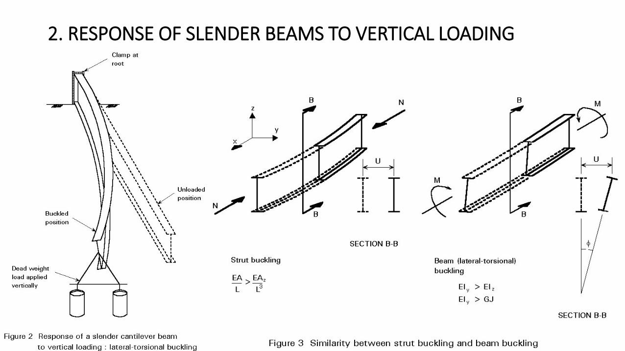
2. RESPONSE OF SLENDER BEAMS TO VERTICAL LOADINGIt is known from our understanding of the behaviour of struts that, whenever a slender structural element is loaded in its stiff plane (axially in the case of the strut), there exists a tendency for it to fail by buckling in a more flexible plane (by deflecting sideways in the case of the strut). Figure 2 illustrates the response of a slender cantilever beam to a vertical end load; this phenomenon is termed lateral-torsional buckling. Although it involves both a lateral deflection (u) and twisting about a vertical axis through the web (f), as shown in Figure 3, this type of instability is quite similar to the simpler flexural buckling of an axially loaded strut. Loading the beam in its stiffer plane (the plane of the web) has induced a failure by buckling in a less stiff-direction (by deflecting sideways and twisting).
Lecture 7.9.1: Unrestrained Beams I 7
2. RESPONSE OF SLENDER BEAMS TO VERTICAL LOADING
Lecture 7.9.1: Unrestrained Beams I 8

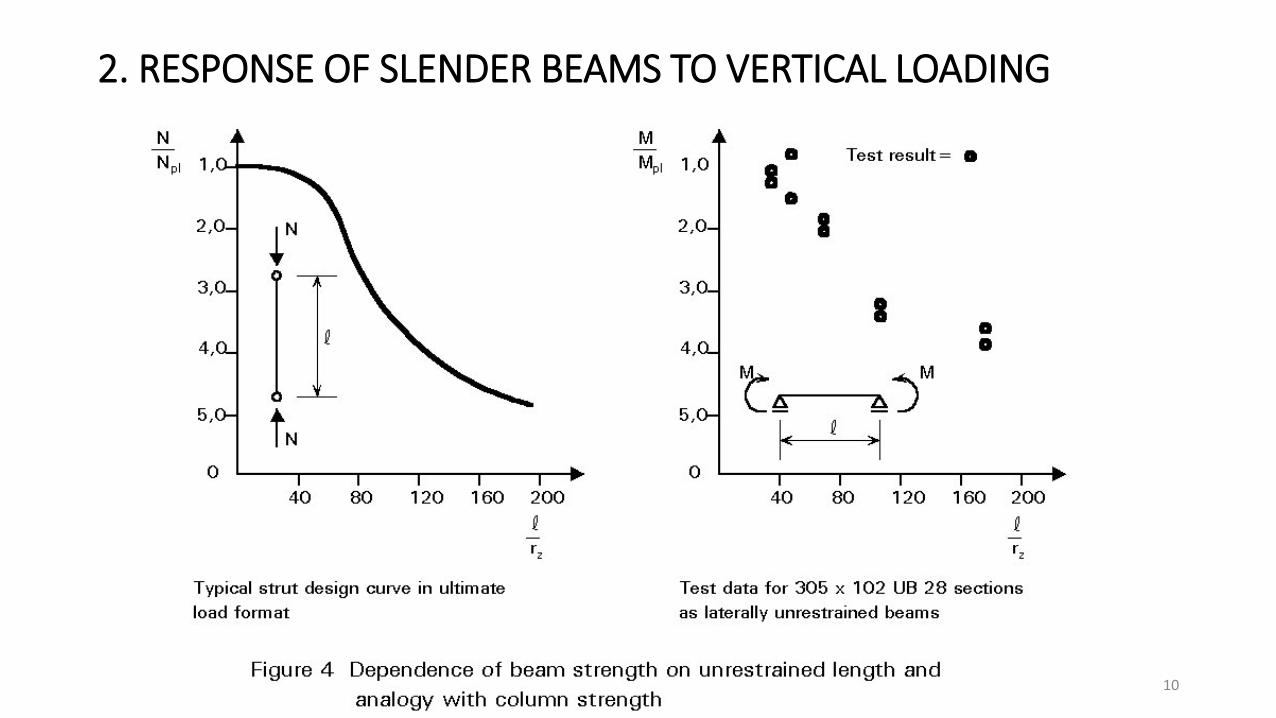
2. RESPONSE OF SLENDER BEAMS TO VERTICAL LOADINGOf course, many types of construction effectively prevent this form of buckling, thereby enabling the beam to be designed with greater efficiency as fully restrained (see Lecture 7.8.1). In this context it is important to realise that during erection of the structure certain beams may well receive far less lateral support than will be the case when floors, decks, bracings, etc., are present, so that stability checks, at this stage, are also necessary.Lateral-torsional instability influences the design of laterally unrestrained beams in much the same way that flexural buckling influences the design of columns. Thus the bending strength will now be a function of the beam's slenderness, as indicated in Figure 4, requiring the use in design of an iterative procedure similar to the use of column curves in strut design. However, because of the type of structural actions involved, the analysis of lateral-torsional buckling is considerably more complex. This is reflected in a design approach which requires a rather greater degree of calculation.
Lecture 7.9.1: Unrestrained Beams I 9
2. RESPONSE OF SLENDER BEAMS TO VERTICAL LOADING
Lecture 7.9.1: Unrestrained Beams I 10

3. SIMPLE PHYSICAL MODELBefore considering the analysis of the problem, it is useful to attempt to gain an insight into the physical behaviour by considering a simplified model. Since bending of an I-section beam is resisted principally by the tensile and compressive forces developed in two flanges, as shown in Figure 5, the compression flange may be regarded as a strut. Compression members exhibit a tendency to buckle and in this case the weaker direction would be for the flange to buckle downwards. However, this is prevented by the presence of the web. Therefore the flange is forced to buckle sideways, which will induce some degree of twisting in the section as the web too is required to deform. Whilst this approach neglects the real influence of torsion and the role of the tension flange, it does, nevertheless, approximate the behaviour of very deep girders with very thin webs or of trusses or open web joists. Indeed, early attempts at analysing lateral-torsional buckling started with this approach.
Lecture 7.9.1: Unrestrained Beams I 11

4. FACTORS INFLUENCING LATERAL STABILITYThe compression flange/strut analogy, discussed in the previous section, is also helpful in understanding the following:1. The buckling load of the beam is likely to be dependent on its unbraced span, i.e.the distance between
points at which lateral deflection is prevented, and on its lateral bending stiffness (ELz) because strut resistance µELz/L2.
2. The shape of the cross-section may be expected to have some influence, with the web and the tension flange being more important for relatively shallow sections, than for deep slender sections. In the former case the proximity of the stable tension flange to the unstable compression flange increases stability and also produces a greater twisting of the cross-section. Thus torsional behaviour becomes more important.
Lecture 7.9.1: Unrestrained Beams I 12

4. FACTORS INFLUENCING LATERAL STABILITY3. For beams under non-uniform moment, the force in the compression flange will no longer be
constant, as shown in Figure 6. Therefore such members might reasonably be expected to be more stable than similar members under a more uniform pattern of moment.
Lecture 7.9.1: Unrestrained Beams I 13

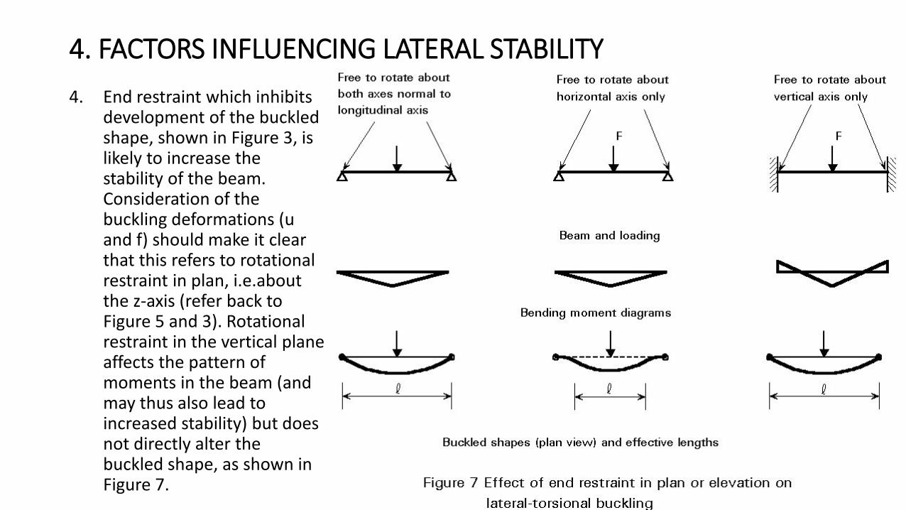
4. FACTORS INFLUENCING LATERAL STABILITY4. End restraint which inhibits
development of the buckled shape, shown in Figure 3, is likely to increase the stability of the beam. Consideration of the buckling deformations (u and f) should make it clear that this refers to rotational restraint in plan, i.e.aboutthe z-axis (refer back to Figure 5 and 3). Rotational restraint in the vertical plane affects the pattern of moments in the beam (and may thus also lead to increased stability) but does not directly alter the buckled shape, as shown in Figure 7. Lecture 7.9.1: Unrestrained Beams I 14
4. FACTORS INFLUENCING LATERAL STABILITY4. End restraint which inhibits
development of the buckled shape, shown in Figure 3, is likely to increase the stability of the beam. Consideration of the buckling deformations (u and f) should make it clear that this refers to rotational restraint in plan, i.e.aboutthe z-axis (refer back to Figure 5 and 3). Rotational restraint in the vertical plane affects the pattern of moments in the beam (and may thus also lead to increased stability) but does not directly alter the buckled shape, as shown in Figure 7. Lecture 7.9.1: Unrestrained Beams I 15

5. BRACING AS A MEANS OF IMPROVING PERFORMANCEBracing may be used to improve the strength of a beam that is liable to lateral-torsional instability. Two requirements are necessary:The bracing must be sufficiently stiff to hold the braced point effectively against lateral movement (this can normally be achieved without difficulty).
The bracing must be sufficiently strong to withstand the forces transmitted to it by the main member (these forces are normally a percentage of the force in the compression flange of the braced member).
Lecture 7.9.1: Unrestrained Beams I 16
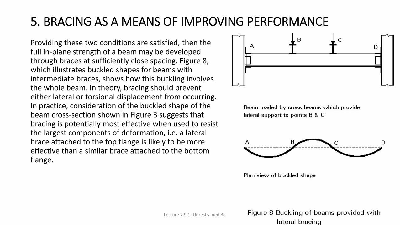
5. BRACING AS A MEANS OF IMPROVING PERFORMANCEProviding these two conditions are satisfied, then the full in-plane strength of a beam may be developed through braces at sufficiently close spacing. Figure 8, which illustrates buckled shapes for beams with intermediate braces, shows how this buckling involves the whole beam. In theory, bracing should prevent either lateral or torsional displacement from occurring. In practice, consideration of the buckled shape of the beam cross-section shown in Figure 3 suggests that bracing is potentially most effective when used to resist the largest components of deformation, i.e. a lateral brace attached to the top flange is likely to be more effective than a similar brace attached to the bottom flange.
Lecture 7.9.1: Unrestrained Beams I 17

6. DESIGN APPLICATIONDirect use of the theory of lateral-torsional instability for design is inappropriate because:• The formulae are too complex for routine use, e.g. Equation
(17) of Lecture 7.9.2.
• Significant differences exist between the assumptions which form the basis of the theory and the characteristics of real beams. Since the theory assumes elastic behaviour, it provides an upper bound on the true strength (this point is discussed in general terms in Lecture 6.6.2).
Figure 9 compares a typical set of lateral-torsional buckling test data obtained using actual hot-rolled sections with the theoretical elastic critical moments given
Lecture 7.9.1: Unrestrained Beams I 18

6. DESIGN APPLICATIONIn Figure 9a only one set of data for a narrow flanged beam section is shown. The use of the λLT non-dimensional format in Figure 9b has the advantage of permitting results from different test series (using different cross-sections and different material strengths) to be compared directly. In both figures three distinct regions of behaviour can be observed:• Stocky beams which are able to attain Mpl, with values of λLT below about 0,4 in Figure 9b.
• Slender beams which fail at moments close to Mcr, with values of λLT above 1,2 in Figure 9b.• Beams of intermediate slenderness which fail to reach either Mpl or Mcr, with 0,4 < λLT < 1,2 in
Figure 9b.Only in the case of beams in region 1 does lateral stability not influence design. For beams in region 2, which covers much of the practical range of beams without lateral restraint, design must be based on considerations of inelastic buckling suitably modified to allow for geometrical imperfections, residual stresses, etc.,. Thus both theory and tests must play a part, with the inherent complexity of the problem being such that the final design rules are likely to involve some degree of empiricism.
Lecture 7.9.1: Unrestrained Beams I 19

6. DESIGN APPLICATIONSection 7 outlines the provisions of Eurocode 3 [1] with regard to beam design, assuming typical sections as shown in Figure 10a and 10b. It should be noted that sections of the type illustrated in Figure 10b, with one axis of symmetry, e.g.channels, may only be included if the section is bent about the axis of symmetry, i.e. loads are applied through the shear centre parallel to the web of the channel. Singly-symmetrical sections bent in the other plane, e.g. an unequal flanged I-section bent about its major-axis as shown in Figure 10c, may only be treated by an extended version of the theory, principally because the section's shear centre no longer lies on the neutral axis.
Lecture 7.9.1: Unrestrained Beams I 20

7. METHOD OF EUROCODE 3The buckling resistance moment [1] is given by:
MbRd = χLT MRd (1)where MRd is the moment resistance of the cross-section
χLT is the reduction factor for lateral-torsional bucklingIn determining MRd the section classification should, of course, be noted and the appropriate section modulus used in conjunction with the material design strength fd. The value of χLT depends on the beam's slenderness λLT and is given by:
χLT = 1/ {φLT + [φLT2
- λLT2]1/2} (2)
where φLT = 0,5 [1 + αLT(λLT - 0,20) + λLT2]
and αLT = 0,21 for rolled sectionsαLT = 0,49 for welded beams
Lecture 7.9.1: Unrestrained Beams I 21

7. METHOD OF EUROCODE 3Figure 11 illustrates the relationship between cLT and λLT, showing how it follows the pattern of behaviour exhibited by the test data of Figure 9. When λLT <= 0,4, the value of χLT is sufficiently close to unity that design may be based on the full resistance moment MRd.
Lecture 7.9.1: Unrestrained Beams I 22

7. METHOD OF EUROCODE 3The slenderness λLT, which is a measure of the extent to which lateral-torsional buckling reduces a beam's load carrying resistance, is a function of MRd and Mcr. Mcr is the elastic critical buckling moment, a quantity similar in concept to the Euler load for a strut since it is derived from a theory (see Lecture 7.9.2) that assumes "perfect" behaviour, i.e. an initially straight member, elastic response, no misalignment of the loading, etc..Thus λLT is taken as:
λLT = [MRd / Mcr]1/2 (3)For calculation purposes Equation (3) may be rewritten as:λLT = [λLT / λ1] (4)
where λ1 = π[E/fy]1/2
= 93,9[235/fy]1/2
where
and ψ is the end moment ratio defined in Figure 13.
Lecture 7.9.1: Unrestrained Beams I 23

7. METHOD OF EUROCODE 3Taking as an example the end span of a continuous beam for which y = 0 gives C1=1,75 and thus λLT will be reduced to 0,76 (= 1/ √1,75) of the value for uniform moment, leading to an increase in χLT and thus in MbRd.Variations in the conditions of lateral restraint may be treated by introducing k-coefficients to modify the geometrical length L into kL when determining Mcr. For conditions with more restraint, values of k < 1,0 are appropriate, leading to an increase in Mcr and thus, via a reduction in λLT , to increases in χLT and MbRd.
Lecture 7.9.1: Unrestrained Beams I 24

7. METHOD OF EUROCODE 3Similarly additional C-coefficients may be used directly in the determination of Mcr to provide modified values of λLT appropriate for a wide range of load types. In particular, this method should be used to calculate the reduced Mcr appropriate for destabilising loads. These are loads that act above the level of the beam's shear centreand are free to move sideways with the beam as it buckles, as shown in Figure 14.For cross-sections of the type illustrated in Figure 9c, for which the shear centre and centroid do not lie on the same horizontal axis, evaluation of Mcr becomes more complex.
Lecture 7.9.1: Unrestrained Beams I 25
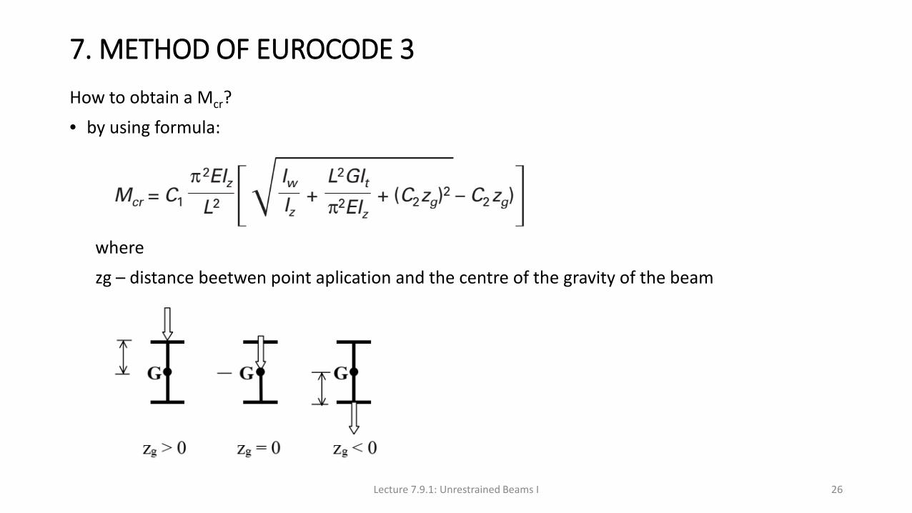
7. METHOD OF EUROCODE 3How to obtain a Mcr?• by using formula:
wherezg – distance beetwen point aplication and the centre of the gravity of the beam
Lecture 7.9.1: Unrestrained Beams I 26

7. METHOD OF EUROCODE 3C1, C2 – coefficients responsible for adjusting formula to real bending moment distribution.
Lecture 7.9.1: Unrestrained Beams I 27

7. METHOD OF EUROCODE 3• by using numerical analysis:
• LTBeam
Lecture 7.9.1: Unrestrained Beams I 28
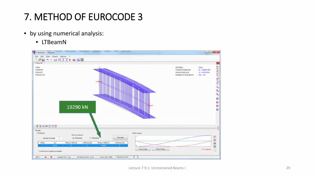
7. METHOD OF EUROCODE 3• by using numerical analysis:
• LTBeamN
Lecture 7.9.1: Unrestrained Beams I 29

7. METHOD OF EUROCODE 3• by using numerical analysis:
• advanced numericalsystems (Abaus, Ansys,…)
Lecture 7.9.1: Unrestrained Beams I 30

8. CONCLUDING SUMMARY• Beams that are not restrained along their length and are bent about their strong axis are subject
to lateral torsional buckling.• Unbraced span, lateral slenderness (L/iz), cross-sectional shape (torsional and warping rigidities),
moment distribution and end restraint are the primary influences on buckling resistance.
• Bracing of sufficient stiffness and strength, that restrains either torsional or lateral deformations, may be used to increase buckling resistance.
• Although elastic critical load theory provides a background for understanding the behaviour of laterally unrestrained beams, it requires both simplifications and empirical modification if it is to form a suitable basis for a design approach.
• In order to check the lateral buckling resistance of a trial section, its effective slenderness λLT must first be obtained.
• Variation in either lateral support conditions or the form of the applied loading may be accommodated in the design process by means of coefficients k and C, used to modify either the basic slenderness λLT or the basic elastic critical moment Mcr.
Lecture 7.9.1: Unrestrained Beams I 31

9. REFERENCES[1] Eurocode 3: "Design of Steel Structures": ENV 1993-1-1: Part 1.1: General rules and rules for buildings, CEN, 1992.
Lecture 7.9.1: Unrestrained Beams I 32

10. ADDITIONAL READING1. Narayanan, R., Editor, "Beams and Beam Columns: Stability and Strength", Applied Science
Publishers 1983.2. Chen, W. F. and Atsuta, T. "Theory of Beam Columns Volume 2, Space Behaviour and Design",
McGraw Hill 1977.Chapter 3 deals with laterally unrestrained beams.
3. Timoshenko, S. P. and Gere, J. M., "Theory of Elastic Stability" Second Edition, McGraw Hill 1961.Basic derivations for the elastic critical moment for a variety of beam problems are provided in Chapter 6.
4. Bleich, F., "Buckling Strength of Metal Structures", McGraw Hill 1952.Chapter 4 presents the basic theory of lateral buckling of beams.
5. Galambos, T. V., "Structural Members and Frames", Prentiss Hall 1968.Chapter 2 deals with the fundamentals of elastic behaviour, whilst Chapter 3 covers elastic and inelastic behaviour and design of laterally unrestrained beams.
6. Trahair, N. S. and Bradford, M. A., "The Behaviour and Design of Steel Structures", Chapman and Hall, Second Edition, 1988.
7. Laterally unrestrained beams are dealt with in Chapter 6.Lecture 7.9.1: Unrestrained Beams I 33