lecture 7: pumps, energy equation with pumps, pump...
TRANSCRIPT
Copyright ©2010, ©1996 by Pearson Education, Inc.
All rights reserved.
Fundamentals of Hydraulic Engineering Systems, Fourth Edition
Robert J. Houghtalen • A. Osman Akan • Ned H. C. Hwang
ENVE 204
LECTURE 7:
Pumps, energy equation with
pumps, pump curves, pumps in
parallel, pumps in series

Copyright ©2010, ©1996 by Pearson Education, Inc.
All rights reserved.
Fundamentals of Hydraulic Engineering Systems, Fourth Edition
Robert J. Houghtalen • A. Osman Akan • Ned H. C. Hwang
PUMPS
Pumps are divided into:
• Roto-dynamic or centrifugal pumps and
• Positive displacement pumps
Within these main groups there are many
different types of pumps

Copyright ©2010, ©1996 by Pearson Education, Inc.
All rights reserved.
Fundamentals of Hydraulic Engineering Systems, Fourth Edition
Robert J. Houghtalen • A. Osman Akan • Ned H. C. Hwang
Turbo-hydraulic pumps
Move fluids with a rotating vane or another moving fluid.
•Centrifugal pumps
•Propeller pumps
•Jet pumps
Positive-displacement pumps
Move fluids strictly by presice machine displacements such
as a gear system rotating with a closed housing (screw
pumps) or a piston moving in a sealed cylinder (reciprocal
pumps)
Copyright ©2010, ©1996 by Pearson Education, Inc.
All rights reserved.
Fundamentals of Hydraulic Engineering Systems, Fourth Edition
Robert J. Houghtalen • A. Osman Akan • Ned H. C. Hwang
Centrifugal pumps
Reciprocating Pump
Screw pump

Copyright ©2010, ©1996 by Pearson Education, Inc.
All rights reserved.
Fundamentals of Hydraulic Engineering Systems, Fourth Edition
Robert J. Houghtalen • A. Osman Akan • Ned H. C. Hwang
CENTRIFUGAL PUMP
• A centrifugal pump is one of the simplest equipment pieces in any process plant
• Purpose: convert energy of a motor velocity or kinetic energy pressure energy of a fluid.
Two main parts of the pump
1) impeller : rotating part (convert driver energy into kinetic energy)
2) diffuser: stationary part (convert kinetic energy into pressure energy)

Copyright ©2010, ©1996 by Pearson Education, Inc.
All rights reserved.
Fundamentals of Hydraulic Engineering Systems, Fourth Edition
Robert J. Houghtalen • A. Osman Akan • Ned H. C. Hwang
Figure 5.1 Demour’s centrifugal pump

Copyright ©2010, ©1996 by Pearson Education, Inc.
All rights reserved.
Fundamentals of Hydraulic Engineering Systems, Fourth Edition
Robert J. Houghtalen • A. Osman Akan • Ned H. C. Hwang
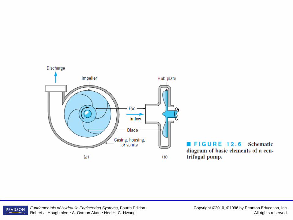
Liquid flow path inside a centrifugal
pump
Copyright ©2010, ©1996 by Pearson Education, Inc.
All rights reserved.
Fundamentals of Hydraulic Engineering Systems, Fourth Edition
Robert J. Houghtalen • A. Osman Akan • Ned H. C. Hwang
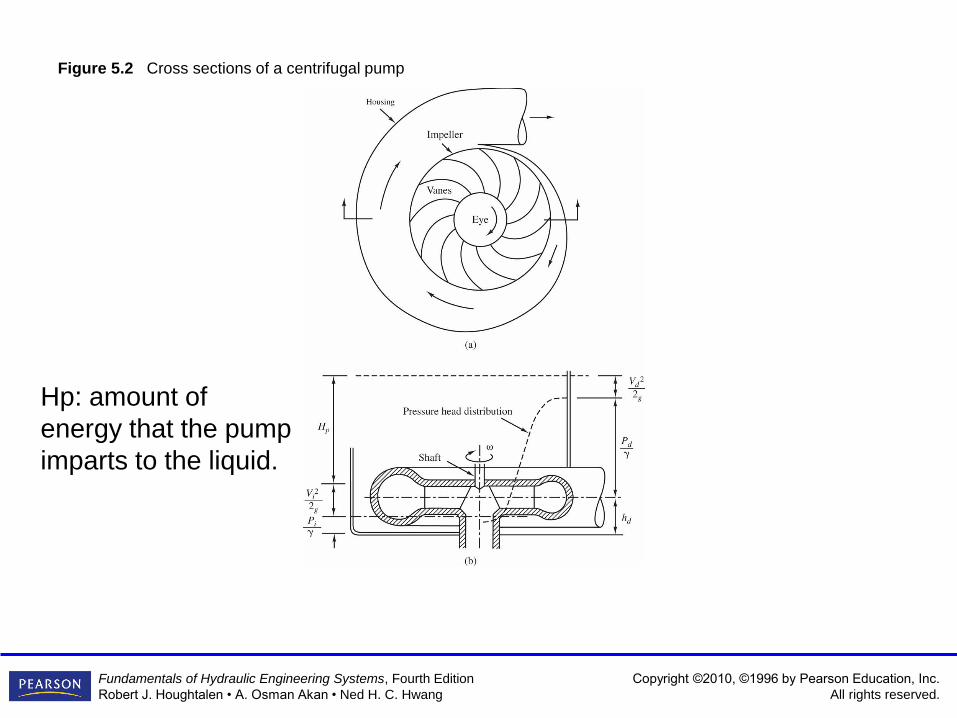
Figure 5.2 Cross sections of a centrifugal pump
Hp: amount of
energy that the pump
imparts to the liquid.
Copyright ©2010, ©1996 by Pearson Education, Inc.
All rights reserved.
Fundamentals of Hydraulic Engineering Systems, Fourth Edition
Robert J. Houghtalen • A. Osman Akan • Ned H. C. Hwang
Copyright ©2010, ©1996 by Pearson Education, Inc.
All rights reserved.
Fundamentals of Hydraulic Engineering Systems, Fourth Edition
Robert J. Houghtalen • A. Osman Akan • Ned H. C. Hwang
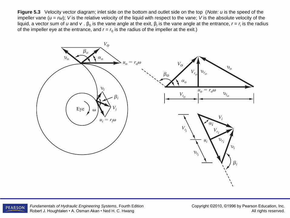
Figure 5.3 Velocity vector diagram; inlet side on the bottom and outlet side on the top (Note: u is the speed of the
impeller vane (u = rω); V is the relative velocity of the liquid with respect to the vane; V is the absolute velocity of the
liquid, a vector sum of u and ѵ . β0 is the vane angle at the exit, βi is the vane angle at the entrance, r = ri is the radius
of the impeller eye at the entrance, and r = r0 is the radius of the impeller at the exit.)

Copyright ©2010, ©1996 by Pearson Education, Inc.
All rights reserved.
Fundamentals of Hydraulic Engineering Systems, Fourth Edition
Robert J. Houghtalen • A. Osman Akan • Ned H. C. Hwang
Hydraulic Types of Pumps

Copyright ©2010, ©1996 by Pearson Education, Inc.
All rights reserved.
Fundamentals of Hydraulic Engineering Systems, Fourth Edition
Robert J. Houghtalen • A. Osman Akan • Ned H. C. Hwang
Impeller Types

Copyright ©2010, ©1996 by Pearson Education, Inc.
All rights reserved.
Fundamentals of Hydraulic Engineering Systems, Fourth Edition
Robert J. Houghtalen • A. Osman Akan • Ned H. C. Hwang
Figure 5.4 Propeller pump
Copyright ©2010, ©1996 by Pearson Education, Inc.
All rights reserved.
Fundamentals of Hydraulic Engineering Systems, Fourth Edition
Robert J. Houghtalen • A. Osman Akan • Ned H. C. Hwang
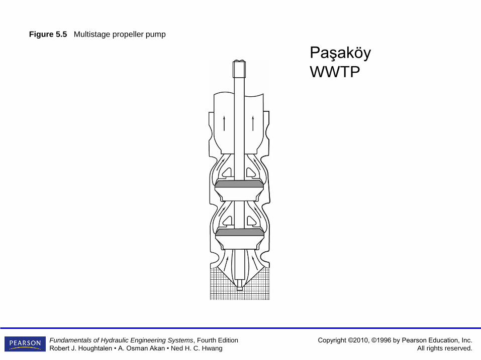
Figure 5.5 Multistage propeller pump
Paşaköy
WWTP

Copyright ©2010, ©1996 by Pearson Education, Inc.
All rights reserved.
Fundamentals of Hydraulic Engineering Systems, Fourth Edition
Robert J. Houghtalen • A. Osman Akan • Ned H. C. Hwang
Figure 5.6 Jet pump

Copyright ©2010, ©1996 by Pearson Education, Inc.
All rights reserved.
Fundamentals of Hydraulic Engineering Systems, Fourth Edition
Robert J. Houghtalen • A. Osman Akan • Ned H. C. Hwang
Figure 5.7 Jet pump as a booster

Copyright ©2010, ©1996 by Pearson Education, Inc.
All rights reserved.
Fundamentals of Hydraulic Engineering Systems, Fourth Edition
Robert J. Houghtalen • A. Osman Akan • Ned H. C. Hwang
Definition of Important Terms
• Capacity
• Head
• BHP (Brake Horse Power)
• BEP (Best Efficiency Point)
• Specific Speed
Copyright ©2010, ©1996 by Pearson Education, Inc.
All rights reserved.
Fundamentals of Hydraulic Engineering Systems, Fourth Edition
Robert J. Houghtalen • A. Osman Akan • Ned H. C. Hwang
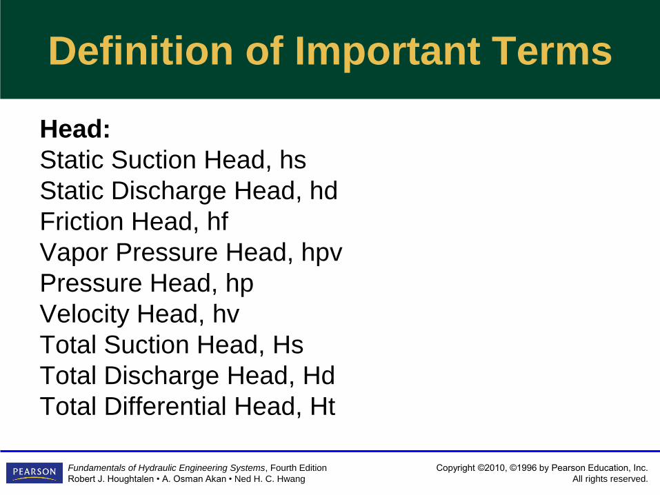
Definition of Important Terms
Head:
Static Suction Head, hs
Static Discharge Head, hd
Friction Head, hf
Vapor Pressure Head, hpv
Pressure Head, hp
Velocity Head, hv
Total Suction Head, Hs
Total Discharge Head, Hd
Total Differential Head, Ht
Copyright ©2010, ©1996 by Pearson Education, Inc.
All rights reserved.
Fundamentals of Hydraulic Engineering Systems, Fourth Edition
Robert J. Houghtalen • A. Osman Akan • Ned H. C. Hwang
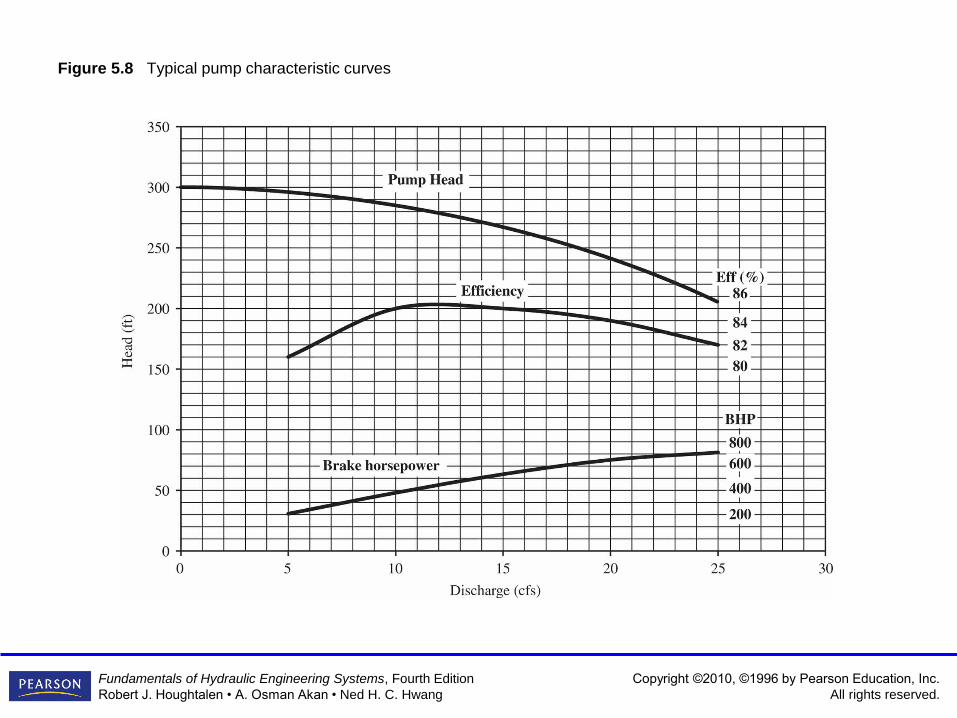
Figure 5.8 Typical pump characteristic curves

Copyright ©2010, ©1996 by Pearson Education, Inc.
All rights reserved.
Fundamentals of Hydraulic Engineering Systems, Fourth Edition
Robert J. Houghtalen • A. Osman Akan • Ned H. C. Hwang
Figure 5.9 Single pump and pipeline
EA+Hp=EB+hfor
Hp=EB-EA+hf-Part of the energy added to the flow by the pump is expended in raising water from
elevation EA to EB
-Part of it expended to overcome the flow resistance
EB-EA= Hs= elevation rise (static head)
Hp= Hs +Hf

Copyright ©2010, ©1996 by Pearson Education, Inc.
All rights reserved.
Fundamentals of Hydraulic Engineering Systems, Fourth Edition
Robert J. Houghtalen • A. Osman Akan • Ned H. C. Hwang
Figure 5.10A Single pump and pipeline analysis

Copyright ©2010, ©1996 by Pearson Education, Inc.
All rights reserved.
Fundamentals of Hydraulic Engineering Systems, Fourth Edition
Robert J. Houghtalen • A. Osman Akan • Ned H. C. Hwang
Figure 5.10B Single pump and pipeline analysis at a different rotational speed

Copyright ©2010, ©1996 by Pearson Education, Inc.
All rights reserved.
Fundamentals of Hydraulic Engineering Systems, Fourth Edition
Robert J. Houghtalen • A. Osman Akan • Ned H. C. Hwang

Copyright ©2010, ©1996 by Pearson Education, Inc.
All rights reserved.
Fundamentals of Hydraulic Engineering Systems, Fourth Edition
Robert J. Houghtalen • A. Osman Akan • Ned H. C. Hwang
Pump performance & efficiency curve

Copyright ©2010, ©1996 by Pearson Education, Inc.
All rights reserved.
Fundamentals of Hydraulic Engineering Systems, Fourth Edition
Robert J. Houghtalen • A. Osman Akan • Ned H. C. Hwang
Operating Conditions (Q, Hp, Eff.)

Copyright ©2010, ©1996 by Pearson Education, Inc.
All rights reserved.
Fundamentals of Hydraulic Engineering Systems, Fourth Edition
Robert J. Houghtalen • A. Osman Akan • Ned H. C. Hwang
Figure 5.11 Pump characteristics for two pumps in parallel
Q1 Q2 Q= Q1+Q2
Copyright ©2010, ©1996 by Pearson Education, Inc.
All rights reserved.
Fundamentals of Hydraulic Engineering Systems, Fourth Edition
Robert J. Houghtalen • A. Osman Akan • Ned H. C. Hwang
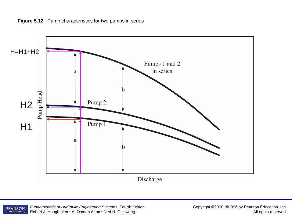
Figure 5.12 Pump characteristics for two pumps in series
H1
H2
H=H1+H2

Copyright ©2010, ©1996 by Pearson Education, Inc.
All rights reserved.
Fundamentals of Hydraulic Engineering Systems, Fourth Edition
Robert J. Houghtalen • A. Osman Akan • Ned H. C. Hwang
Figure 5.13 Typical performance curves of two pumps connected in parallel B and in series C
Copyright ©2010, ©1996 by Pearson Education, Inc.
All rights reserved.
Fundamentals of Hydraulic Engineering Systems, Fourth Edition
Robert J. Houghtalen • A. Osman Akan • Ned H. C. Hwang
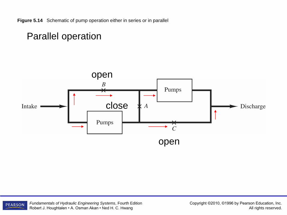
Figure 5.14 Schematic of pump operation either in series or in parallel
Parallel operation
open
open
close

Copyright ©2010, ©1996 by Pearson Education, Inc.
All rights reserved.
Fundamentals of Hydraulic Engineering Systems, Fourth Edition
Robert J. Houghtalen • A. Osman Akan • Ned H. C. Hwang
Figure 5.14 Schematic of pump operation either in series or in parallel
Series operation
close
close
open

Copyright ©2010, ©1996 by Pearson Education, Inc.
All rights reserved.
Fundamentals of Hydraulic Engineering Systems, Fourth Edition
Robert J. Houghtalen • A. Osman Akan • Ned H. C. Hwang
Figure 5.15 Single pump and two pipes

Copyright ©2010, ©1996 by Pearson Education, Inc.
All rights reserved.
Fundamentals of Hydraulic Engineering Systems, Fourth Edition
Robert J. Houghtalen • A. Osman Akan • Ned H. C. Hwang
Figure 5.16 Graphical solution for Example 5.5

Copyright ©2010, ©1996 by Pearson Education, Inc.
All rights reserved.
Fundamentals of Hydraulic Engineering Systems, Fourth Edition
Robert J. Houghtalen • A. Osman Akan • Ned H. C. Hwang
Figure 5.17 Branching pipe system of Example 5.6

Copyright ©2010, ©1996 by Pearson Education, Inc.
All rights reserved.
Fundamentals of Hydraulic Engineering Systems, Fourth Edition
Robert J. Houghtalen • A. Osman Akan • Ned H. C. Hwang
Figure 5.18 Graphical solution for Example 5.6

Copyright ©2010, ©1996 by Pearson Education, Inc.
All rights reserved.
Fundamentals of Hydraulic Engineering Systems, Fourth Edition
Robert J. Houghtalen • A. Osman Akan • Ned H. C. Hwang
Figure 5.19 Pipe network for Example 5.7

Copyright ©2010, ©1996 by Pearson Education, Inc.
All rights reserved.
Fundamentals of Hydraulic Engineering Systems, Fourth Edition
Robert J. Houghtalen • A. Osman Akan • Ned H. C. Hwang
Figure 5.20 Energy and pressure relationship in a centrifugal pump

Copyright ©2010, ©1996 by Pearson Education, Inc.
All rights reserved.
Fundamentals of Hydraulic Engineering Systems, Fourth Edition
Robert J. Houghtalen • A. Osman Akan • Ned H. C. Hwang
Table 5.1 Conversion of Specific Speed

Copyright ©2010, ©1996 by Pearson Education, Inc.
All rights reserved.
Fundamentals of Hydraulic Engineering Systems, Fourth Edition
Robert J. Houghtalen • A. Osman Akan • Ned H. C. Hwang
Figure 5.21 Relative impeller shapes and the approximate values of shape numbers, S, as defined in Table 5.1

Copyright ©2010, ©1996 by Pearson Education, Inc.
All rights reserved.
Fundamentals of Hydraulic Engineering Systems, Fourth Edition
Robert J. Houghtalen • A. Osman Akan • Ned H. C. Hwang
Figure 5.22 Discharge, head, and power requirements of different types of pumps

Copyright ©2010, ©1996 by Pearson Education, Inc.
All rights reserved.
Fundamentals of Hydraulic Engineering Systems, Fourth Edition
Robert J. Houghtalen • A. Osman Akan • Ned H. C. Hwang
Figure 5.23 Pump model selection chart
Copyright ©2010, ©1996 by Pearson Education, Inc.
All rights reserved.
Fundamentals of Hydraulic Engineering Systems, Fourth Edition
Robert J. Houghtalen • A. Osman Akan • Ned H. C. Hwang
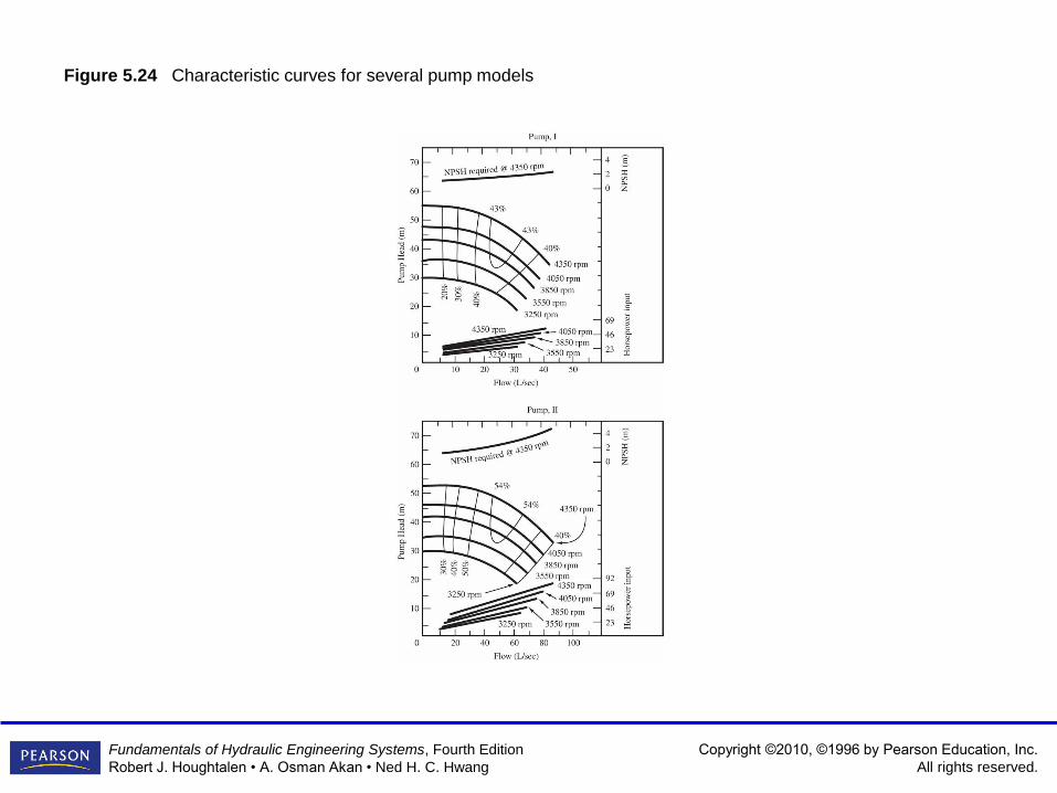
Figure 5.24 Characteristic curves for several pump models

Copyright ©2010, ©1996 by Pearson Education, Inc.
All rights reserved.
Fundamentals of Hydraulic Engineering Systems, Fourth Edition
Robert J. Houghtalen • A. Osman Akan • Ned H. C. Hwang
Figure 5.24 (continued) Characteristic curves for several pump models

Copyright ©2010, ©1996 by Pearson Education, Inc.
All rights reserved.
Fundamentals of Hydraulic Engineering Systems, Fourth Edition
Robert J. Houghtalen • A. Osman Akan • Ned H. C. Hwang
Problem 5.4.5 (Hwang, 3rd Edition) : A 70-kW motor is avaliable to drive one of
the pumps shown in Figure 5.24. The system is designed to deliver a minimum
discharge of 80 L/s, over an elevation difference of 20 m. The system uses a
wrought iron pipe, 150 m long and 15 cm in diameter to transport water at 100C.
Select the pump based on the consideration of lowest energy consumption.
Min. Desired flowrate: 80 l/s (Pump III or IV can be used)
70 kw motor is avaliable
Static Head: 20 m, e: 0.045 (wrought iron pipe), L:150 m, D:
0.15 m, T: 100C.

Copyright ©2010, ©1996 by Pearson Education, Inc.
All rights reserved.
Fundamentals of Hydraulic Engineering Systems, Fourth Edition
Robert J. Houghtalen • A. Osman Akan • Ned H. C. Hwang
Pump III
3250 rpm
Q=52 L/s < 80 L/s
3550 rpm
Q=65 L/s < 80 L/s
3850 rpm
Q= 80 l/s
H=39 m
Eff= 59 %
4050 rpm
Q=86 L/s
H=42 m, Eff= 58-59 %

Copyright ©2010, ©1996 by Pearson Education, Inc.
All rights reserved.
Fundamentals of Hydraulic Engineering Systems, Fourth Edition
Robert J. Houghtalen • A. Osman Akan • Ned H. C. Hwang
Pump IV
3250 rpm
Q=55 L/s < 80 L/s
3550 rpm
Q=74 L/s < 80 L/s
3850 rpm
Q= 85 l/s
H=38 m
Eff= 55 %

Copyright ©2010, ©1996 by Pearson Education, Inc.
All rights reserved.
Fundamentals of Hydraulic Engineering Systems, Fourth Edition
Robert J. Houghtalen • A. Osman Akan • Ned H. C. Hwang
Pump III
3850 rpm
Q= 80 l/s
H=39 m
Eff= 59 %
Pump IV
3850 rpm
Q= 85 l/s
H=38 m
Eff= 55 %

Copyright ©2010, ©1996 by Pearson Education, Inc.
All rights reserved.
Fundamentals of Hydraulic Engineering Systems, Fourth Edition
Robert J. Houghtalen • A. Osman Akan • Ned H. C. Hwang
Pump III
3250 rpm
Q=52 L/s < 80 L/s
3550 rpm
Q=65 L/s < 80 L/s
3850 rpm
Q= 80 l/s
H=39 m
Eff= 59 %
4050 rpm
Q=86 L/s
H=42 m, Eff= 58-59 %

Copyright ©2010, ©1996 by Pearson Education, Inc.
All rights reserved.
Fundamentals of Hydraulic Engineering Systems, Fourth Edition
Robert J. Houghtalen • A. Osman Akan • Ned H. C. Hwang
Pump IV
3250 rpm
Q=55 L/s < 80 L/s
3550 rpm
Q=74 L/s < 80 L/s
3850 rpm
Q= 85 l/s
H=38 m
Eff= 55 %