lecture 8: finite state machines · lecture 8: finite state machines ... moore mars life...
TRANSCRIPT

Lecture 8: Finite State Machines
And Sequential circuit Design
CSE 140: Components and Design Techniques for Digital Systems
Diba Mirza
Dept. of Computer Science and Engineering University of California, San Diego
1
2
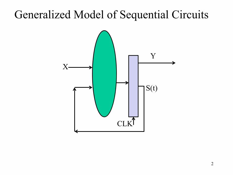
Generalized Model of Sequential Circuits
S(t)
X Y
CLK

3
Mealy Machine: yi(t) = fi(X(t), S(t)) Moore Machine: yi(t) = fi(S(t))
si(t+1) = gi(X(t), S(t))
C1 C2
CLK
x(t)
y(t)
Mealy Machine
S(t)
C1 C2
CLK
x(t) y(t)
Moore Machine S(t)
Canonical Form: Mealy and Moore Machines

4
C1 C2
CLK
x(t)
y(t)
Mealy Machine
C1 C2
CLK
x(t) y(t)
Moore Machine S(t) S(t)
Differences in State Diagram: Mealy vs. Moore Machines

This Counter Design Is: A. Moore machine B. Mealy machine C. None of the above
D Q D Q D Q
OUT1 OUT2 OUT3
CLK
"1"

Life on Mars?
6
This pattern recognizer should have A. One state because it has one output B. One state because it has one input C. Two states because the input can be 0 or 1 D. More than two states because …. E. None of the above
Mars rover has a binary input x. When it receives the input sequence x(t-2, t) = 001 from its life detection sensors, it means that the it has detected life on Mars J and the output y(t) = 1, otherwise y(t) = 0 (no life on Mars L).
Implement the Life-on-Mars Pattern Recognizer!

Life on Mars?
7
Mars rover has a binary input x. When it receives the input sequence x(t-2, t) = 001 from its life detection sensors, it means that the it has detected life on Mars J and the output y(t) = 1, otherwise y(t) = 0 (no life on Mars L).

Mars Life Recognizer FSM
8
S1 S0 0/0
1/0
0/0
1/1
S2 0/0
1/0
Which of the following diagrams is a correct Mealy solution for the 001 pattern recognizer on the Mars rover?
A.
S1 S0 0/0
1/0
1/0
0/0
S2 1/1
B. 0/0
C. Both A and B are correct
D. None of the above

9
Pattern Recognizer ‘001’
S1 S0 0/0
1/0
0/0
1/1
S2 0/0
1/0
C1 C2
CLK
x(t)
y(t)
Mealy Machine
S(t)
What does state table need to show to design controls of C1? A. (current input x(t), current state S(t) vs. next state, S(t+1)) B. (current input, current state vs. current output y(t)) C. (current input, current state vs. current output, next state) D. None of the above
Mars Life Recognizer FFs

10
State Diagram => State Table with State Assignment
State Assignment S0: 00 S1: 01 S2: 10
S(t)\x 0 1
S0 S1,0 S0,0
S1 S2,0 S0,0
S2 S2,0 S0,1
S(t)\x 0 1
00 01,0 00,0
01 10,0 00,0
10 10,0 00,1 Q1(t+1)Q0(t+1), y
C1 C2
CLK
x(t)
y(t)
Mealy Machine S(t)
S1 S0 0/0
1/0
0/0
1/1
S2 0/0
1/0

11
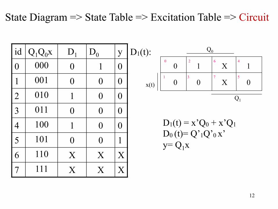
State Diagram => State Table => Excitation Table => Circuit
Q1(t) Q0(t)\x 0 1 00 01,0 00,0 01 10,0 00,0 10 10,0 00,1
id Q1Q0x D1 D0 y 0 000 0 1 0 1 001 0 0 0 2 010 1 0 0 3 011 0 0 0 4 100 1 0 0 5 101 0 0 1 6 110 X X X 7 111 X X X
C1 C2
CLK
x(t)
y(t)
Mealy Machine S(t)
12
0 2 6 4
1 3 7 5
x(t)
Q1
0 1 X 1
0 0 X 0
Q0 D1(t):
D1(t) = x’Q0 + x’Q1 D0 (t)= Q’1Q’0 x’ y= Q1x
State Diagram => State Table => Excitation Table => Circuit
id Q1Q0x D1 D0 y 0 000 0 1 0 1 001 0 0 0 2 010 1 0 0 3 011 0 0 0 4 100 1 0 0 5 101 0 0 1 6 110 X X X 7 111 X X X

13
D1(t) = x’Q0 + x’Q1 D0 (t)= Q’1Q’0 x’ y= Q1x
D Q
Q’
D Q
Q’
Q1
Q0
D1
D0
Q0
Q1
x’
x
y
Q’1
Q’0 x’
State Diagram => State Table => Excitation Table => Circuit
C1 C2
CLK
x(t)
y(t)
Mealy Machine S(t)

Moore FSM for the Mars Life Recognizer
14
S1 S0 0/0
1/0
0/0
1/1
S2 0/0
1/0
Which of the following diagrams is a correct Moore solution to the ‘001’ pattern recognizer?
A.
B.
C. Both A and B are correct D. None of the above
S1 0
S0 0
0
1
0
1 S2 0
0
1
S3 1
1 0

Moore Mars Life Recognizer: FF Input Specs
15
Pattern Recognizer ‘001’
What does state table need to show to design controls of C2? A. (current input x(t), current state S(t) vs. next state, S(t+1)) B. (current input, current state vs. current output y(t)) C. (current state vs. current output y(t) and next state) D. (current state vs. current output y(t) ) E. None of the above
C1 C2
CLK
x(t) y(t)
Moore Machine S(t)
S1 0
S0 0
0
1
0
1 S2 0
0
1
S3 1
1 0

Q1Q0\x 0 1
00 01,0 00,0
01 10,0 00,0
10 10,0 11,0
11 01,1 00,1 Q1(t+1)Q0(t+1), y
ID Q1Q0x D1 D0 y 0 000 0 1 0 1 001 0 0 0 2 010 1 0 0 3 011 0 0 0 4 100 1 0 0 5 101 1 1 0 6 110 0 1 1 7 111 0 0 1
S(t)\x 0 1
S0 S1,0 S0,0
S1 S2,0 S0,0
S2 S2,0 S3,0
S3 S1,1 S0,1
Moore Mars Life Recognizer: State Table
S1 0
S0 0
0
1
0
1 S2 0
0
1
S3 1
1 0

id Q1Q0x D1 D0 y 0 000 0 1 0 1 001 0 0 0 2 010 1 0 0 3 011 0 0 0 4 100 1 0 0 5 101 1 1 0 6 110 0 1 1 7 111 0 0 1
0 2 6 4
1 3 7 5
x(t)
Q1
1 0 1 0
0 0 0 1
Q0 D0(t):
0 2 6 4
1 3 7 5
x(t)
Q1
0 1 0 1
0 0 0 1
Q0 D1(t):
0 2 6 4
1 3 7 5
x(t)
Q1
0 0 1 0
0 0 1 0
Q0 y(t):
Mars Life Recognizer: Combinational Circuit Design

Mars Life Recognizer Circuit Implementation
18
D Q
Q’
D Q
Q’
Q1
Q0
D1
D0 y
State Diagram => State Table => Excitation Table => Circuit
C1 C2
CLK
x(t) y(t)
Moore Machine S(t)
D1(t)= Q1(t)Q0(t)’+Q1(t)’Q0(t) x(t) D0(t)= Q1(t)’Q0(t)’x(t)’+ Q1(t)Q0(t) x(t)’+Q1(t)Q0(t)’ x(t) y(t)= Q1(t)Q0(t)

FSM Specification
19
Q0(t)
Q1(t)
D Q
Q’
D Q
Q’
CLK
x(t)
Q0(t)
Q1(t) y(t)

From circuit to FSM
20
Q0(t)
Q1(t)
D Q
Q’
D Q
Q’
CLK
x(t)
Q0(t)
Q1(t)
y(t)
y(t) = Q1(t)Q0(t) Q0(t+1) = D0(t) = x(t)’ Q0(t)’ Q1(t+1) = D1(t) = x(t)’(Q0(t) + Q1(t))

21
State table
0 0 0 1 1 0 1 1
PS input
x=0 x=1
Q1(t) Q0(t) | (Q1(t+1) Q0(t+1), y(t)) Present State | Next State, Output
Netlist ó State Table ó State Diagram ó Input Output Relation Characteristic Expression:
y(t) = Q1(t)Q0(t) Q0(t+1) = D0(t) = x(t)’ Q0(t)’ Q1(t+1) = D1(t) = x(t)’(Q0(t) + Q1(t))

22
State table
0 0 0 1 1 0 1 1
PS input
x=0 x=1 01, 0 00, 0 10, 0 00, 0 11, 0 00, 0 00, 1 00, 1
Q1(t) Q0(t) | Q1(t+1) Q0(t+1), y(t) Present State | Next State, Output
S0 S1 S2 S3
PS input
x=0 x=1 S1, 0 S0, 0 S2, 0 S0, 0 S3, 0 S0, 0 S0, 1 S0, 1
Let: S0 = 00 S1 = 01 S2 = 10 S3 = 11
Remake the state table using symbols instead of binary code , e.g. ’00’
Netlist ó State Table ó State Diagram ó Input Output Relation
State Assignment
y(t) = Q1(t)Q0(t) Q0(t+1) = D0(t) = x(t)’ Q0(t)’ Q1(t+1) = D1(t) = x(t)’(Q0(t) + Q1(t))

23
Netlist ó State Table ó State Diagram ó Input Output Relation
S1 S2 S3 S0 S0 S1 S2 S3
PS input
x=0 x=1 S1, 0 S0, 0 S2, 0 S0, 0 S3, 0 S0, 0 S0, 1 S0, 1

24
Netlist ó State Table ó State Diagram ó Input Output Relation
Example: Given inputs and initial state, derive output sequence
Time 0 1 2 3 4 5 Input 0 1 0 0 0 - State S0 S1 S0 S1 S2 S3 Output 0 0 0 0 0 1
(0 or 1)
S0 S1 S2 S3
PS input
x=0 x=1 S1, 0 S0, 0 S2, 0 S0, 0 S3, 0 S0, 0 S0, 1 S0, 1
x/y
S1 0
S2 0
S3 1
S0 0 0 0 0
1
1 1

25
Finite State Machine Example • Traffic light controller
– Traffic sensors: TA, TB (TRUE when there’s traffic) – Lights: LA, LB
TA
LA
TA
LB
TB
TB
LA
LB
Academic Ave.Bravado
Blvd.
Dorms
Fields
DiningHall
Labs

26
FSM Black Box • Inputs: CLK, Reset, TA, TB
• Outputs: LA, LB
TA
TB
LA
LB
CLK
Reset
TrafficLight
Controller

27
FSM State Transition Diagram • Moore FSM: outputs labeled in each state • States: Circles • Transitions: Arcs
S0LA: greenLB: red
ResetTA
LA
TA
LB
TB
TB
LA
LB
Academic Ave.
BravadoBlvd.
Dorms
Fields
DiningHall
Labs

28
FSM State Transition Diagram • Moore FSM: outputs labeled in each state
S0LA: greenLB: red
S1LA: yellowLB: red
S3LA: redLB: yellow
S2LA: redLB: green
TATA
TB
TB
Reset
Which of the following is true about the controller? A. The traffic light on Academic Ave
(LA) remains green as long as there is traffic on that street
B. The traffic light on both avenues are green for exactly once clock cycle in every four clock cycles
TA
LA
TA
LB
TB
TB
LA
LB
Academic Ave.
BravadoBlvd.
Dorms
Fields
DiningHall
Labs

29
FSM State Transition Table
PS Inputs NS Output
TA TB LA LB S0 0 X S1
S0 1 X S0
S1 X X S2
S2 X 0 S3
S2 X 1 S2
S3 X X S0
S0LA: greenLB: red
S1LA: yellowLB: red
S3LA: redLB: yellow
S2LA: redLB: green
TATA
TB
TB
Reset

30
FSM State Transition Table PS Inputs NS Output
TA TB LA LB S0 0 X S1 green red
S0 1 X S0 green red
S1 X X S2 yellow red
S2 X 0 S3 red green
S2 X 1 S2 red green
S3 X X S0 red yellow
S0LA: greenLB: red
S1LA: yellowLB: red
S3LA: redLB: yellow
S2LA: redLB: green
TATA
TB
TB
Reset
State Encoding
S0 00
S1 01
S2 10
S3 11
PS Inputs NS
Q1(t) Q0(t) TA TB Q1(t +1) Q0(t +1)
0 0 0 X 0 1
0 0 1 X 0 0
0 1 X X 1 0
1 0 X 0 1 1
1 0 X 1 1 0
1 1 X X 0 0

31
State Transition Table PS Inputs NS
Q1(t) Q0(t) TA TB Q1(t +1) Q0(t +1) 0 0 0 X 0 1 0 0 1 X 0 0 0 1 X X 1 0 1 0 X 0 1 1 1 0 X 1 1 0 1 1 X X 0 0
Q1(t+1)= Q1(t) xor Q0(t) Q0(t+1)= Q’1(t)Q’0(t)T’A + Q1(t)Q’0(t)T’B
32
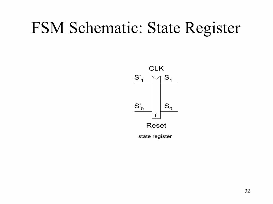
FSM Schematic: State Register
S1
S0
S'1
S'0
CLK
state register
Reset
r

33
Logic Diagram
S1
S0
S'1
S'0
CLK
next state logic state register
Reset
TA
TB
inputs
S1 S0
r
Q1(t+1)= Q1(t) xor Q0(t) Q0(t+1)= Q’1(t)Q’0(t)T’A + Q1(t)Q’0(t)T’B
S1=Q1 S0=Q0

34
FSM Output Table
PS Outputs
Q1 Q0 LA1 LA0 LB1 LB0
0 0 0 0 1 0
0 1 0 1 1 0
1 0 1 0 0 0
1 1 1 0 0 1
Output Encoding
green 00
yellow 01
red 10
LA1 = Q1 LA0 = Q’1Q0
LB1 = Q’1 LB0 = Q1Q0
PS Inputs NS Output
TA TB LA LB S0 0 X S1 green red
S0 1 X S0 green red
S1 X X S2 yellow red
S2 X 0 S3 red green
S2 X 1 S2 red green
S3 X X S0 red yellow

35
FSM Schematic: Output Logic
S1
S0
S'1
S'0
CLK
next state logic output logicstate register
Reset
LA1
LB1
LB0
LA0
TA
TB
inputs outputs
S1 S0
r
LA1 = Q1 LA0 = Q’1Q0
LB1 = Q’1 LB0 = Q1Q0

Summary: Implementation
36
• Set up canonical form • Mealy or Moore machine
• Identify the next states • state diagram ⇨ state table • state assignment
• Derive excitation table • Inputs of flip flops
• Design the combinational logic • don’t care set utilization