lecture 9 - phase controlled ac-dc converters 9...9.2.4 single-phase, half-controlled bridge...
TRANSCRIPT

ELEC4614 Power Electronics
Lecture 9 - Controlled 1 F. Rahman AC-DC Converters
Lecture 9 - Phase-controlled AC-DC converters Controlled AC-DC rectifier circuits with thyristors are commonly used in applications requiring continuously variable DC supplies from a few kilowatts to several hundreds or thousands of kilowatts. The thyristor switch may be viewed as a controlled diode which is turned on by the gate current; a few milliamps will turn even the largest device ON, when its anode to cathode voltage is positive. Once the thyristor is fired or triggered ON, the gate loses control and the anode current runs its course. The thyristor turns OFF when the anode current falls to zero or below a threshold close to zero, brought about AC supply voltage reversal and the load parameters. The thyristor, therefore, must be turned ON with the desired firing angle synchronously with each cycle of the AC supply voltage. The gate firing control circuit is isolated from the AC mains by means of a synchronizing transformer. When turning on, the gate current must persist until the anode current reaches a threshold called the latching current. In some converter circuits, the firing pulses for each thyristor are maintained for the intended duration of conduction for the thyristor. The firing angle , is normally defined to be the angle for which the output DC voltage is maximum.

ELEC4614 Power Electronics
Lecture 9 - Controlled 2 F. Rahman AC-DC Converters
Figure 9.1(a) Rectifier and phase controller for a half-
wave converter.
Firing ControlCircuit
Vmaxsint
Load
10V
+10V
10V
vsT
vo
Vd
iL
vsync
ELEC4614 Power Electronics
Lecture 9 - Controlled 3 F. Rahman AC-DC Converters
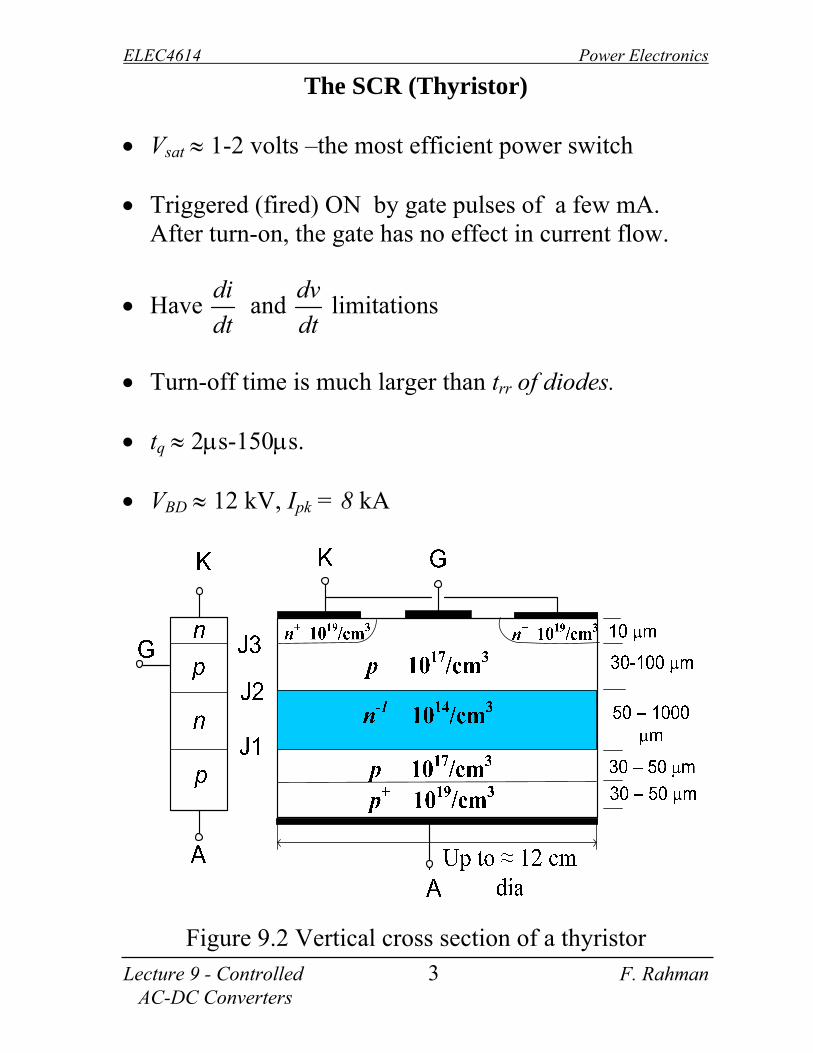
The SCR (Thyristor) Vsat 1-2 volts –the most efficient power switch Triggered (fired) ON by gate pulses of a few mA.
After turn-on, the gate has no effect in current flow.
Have di
dt and
dv
dt limitations
Turn-off time is much larger than trr of diodes. tq 2s-150s. VBD 12 kV, Ipk = 8 kA
Figure 9.2 Vertical cross section of a thyristor

ELEC4614 Power Electronics
Lecture 9 - Controlled 4 F. Rahman AC-DC Converters
Figure 9.3 Top view
Figure 9.4 Thyristor symbol and analogy.
Gate
Wafer
GateCathode
Wafer
G
A K

ELEC4614 Power Electronics
Lecture 9 - Controlled 5 F. Rahman AC-DC Converters
Figure 9.5 Static characteristic of a thyristor
Fdi
dt
tdon = delay time; tr = current rise time;
tps = plasma spreading time in m/sec; tps > tr;
Fdi
dt limiting rate of current rise, A/sec.
Figure 9.6 Thyristor voltage and current transients at turn-on.

ELEC4614 Power Electronics
Lecture 9 - Controlled 6 F. Rahman AC-DC Converters
Fdv
dt
Figure 9.7 Thyristor voltage and current transients at turn-off.

ELEC4614 Power Electronics
Lecture 9 - Controlled 7 F. Rahman AC-DC Converters
9.1 Single-phase half-wave AC – DC converter
Figure 9.8 Half-wave converter and waveforms.

ELEC4614 Power Electronics
Lecture 9 - Controlled 8 F. Rahman AC-DC Converters
9.2 Single-phase controlled converter circuits
9.2.1 Fully-controlled, center-tap thyristor converter
Figure 9.9(a) Converter circuit
(b)
i s 2 T 2
T 1i s 1
V m a x s i n tv s
i p
R
L
i L
v o
v s 1
v s 1

ELEC4614 Power Electronics
Lecture 9 - Controlled 9 F. Rahman AC-DC Converters
(c)
Figure 9.9 Waveforms in the circuit of figure 9.9(a)
Assuming continuous conduction, the output DC voltage is given by
d1
V V sin( t )d( t )max
(9.1)
max2V
cos
(9.2)
The peak reverse voltage of the thyristors is 2Vmax, where Vmax is the peak line to center-tap voltage.

ELEC4614 Power Electronics
Lecture 9 - Controlled 10 F. Rahman AC-DC Converters
Figure 9.10 Vd vs characteristic Note that the fundamental input current waveform now lags the input voltage waveform by , approximately.
Note also that the converter is capable of operating in two quadrants: the first quadrant with positive output DC voltage and current (rectifier operation with 0 90) and the fourth quadrant with negative output voltage and positive output current (inverter operation with 90 180). Operation in the fourth quadrant implies energy flow from the load side to the AC source, which is possible only when the load includes a DC source, such as an overhauling motor. In the absence of such a source, i.e., with passive load only, the converter can not operate continuously in the inversion mode. This means that if the firing angle is increased beyond 90 and the load does not have a DC source, the load current can not be maintained continuous.
Vd

ELEC4614 Power Electronics
Lecture 9 - Controlled 11 F. Rahman AC-DC Converters
Figure 9.11. Operating quadrants. If the load is highly inductive, the load current can be assumed to be smooth and ripple-free. The input current waveform can then be treated as a square-wave, with flat top and 180 conduction angle in each half cycle. Such a waveform easily lends itself to Fourier analysis. The output voltage waveform is also easily analyzed this way. It should be expected that the output voltage ripple will be maximum for = 90, assuming continuous conduction of load current. Because of the single device voltage drop (1.5 V) in the forward path, the center-tap converter is energy efficient. Each secondary winding, however, caries unidirectional current, and each half of the secondary is unused for half of the input AC cycle.
Q1
Q4
V d
Id

ELEC4614 Power Electronics
Lecture 9 - Controlled 12 F. Rahman AC-DC Converters
9.2.2 Single-phase, fully-controlled bridge rectifier (p = 2)
Figure 9.12(a) Single-phase fully-controlled bridge
converter
Figure 9.12(b) Waveforms for α = 45°
Vd
ip
vs = Vmaxsint T1
T2T4
T3 iL
vo
+

ELEC4614 Power Electronics
Lecture 9 - Controlled 13 F. Rahman AC-DC Converters
Figure 9.12(c) Waveforms in the converter of figure 9.12(a) for α = 145°.
Assuming continuous conduction, the dc output voltage is given by
d max1
V V sin td( t )
max2V
cos
(9.3)
where Vmax is peak of the input line-line voltage. Note that for the same dc output voltage, the input AC voltage is now half that of the CT rectifier. This converter operates in quadrants one and four, the latter mode for inversion. Note that there are now two device drops (about 3V) between the transformer and the load. Note also that the transformer secondary current is bi-directional and its

ELEC4614 Power Electronics
Lecture 9 - Controlled 14 F. Rahman AC-DC Converters
phase angle with respect to the ac supply voltage to the converter is roughly given by the firing angle . With continuous conduction, each thyristor conducts for 180 in each cycle.
Vd VS characteristic
Figure 9.13 Voltage regulation characteristic of the converter of figure 9.4(a)
This 2-pulse converter operates in two quadrants, Q1 and Q4.
Figure 9.14. Operating quadrants of fully-controlled, single-phase bridge converter.
Q 1
Q 4
V d
I d
Firing angle,
Vd

ELEC4614 Power Electronics
Lecture 9 - Controlled 15 F. Rahman AC-DC Converters
Analysis of load voltage and input current waveforms
For continuous conduction of smooth, ripple-free load current, the waveforms of the output voltage and the input current are completely specified by the firing angles, supply voltage and the load resistance. For the converters of 9.2.1 and 9.2.2, the output voltage waveform (assuming continuous conduction) can be expressed as:
Figure 9.15 Voltage waveform (a) = 30 and (b) =
90
The ripple voltages in the output are obtained by Fourier analysis of the output voltage waveforms as indicated above. For any firing angle , the Fourier coefficients (amplitudes) for the ac ripple components are given by
max
ncos n 1 cos n 1V
a2 n 1 n 1
(9.4)

ELEC4614 Power Electronics
Lecture 9 - Controlled 16 F. Rahman AC-DC Converters
max
nsin n 1 sin n 1V
b2 n 1 n 1
(9.5)
2 2
n n nv a b (9.7)
for n = 2, 4, 6, …….. The output voltage ripples are the highest for the firing angle of = 90 for which the dc output voltage is zero. In general, the output voltage ripple magnitudes increase as the firing angle is increased from 0 (or reduced from 180) towards 90.
0 30 60 90 120 150 1800
0.2
0.4
0.6
0.8
1
Firing angle in degree
O utput ripples of a 1phase fully controlled rect.
N=2
N=4
N=6
N=8
Figure 9.16. Output voltage harmonics vs firing angle.
For smooth and ripple free load current, the converter input current waveform is an approximate square waveform. Its angular displacement from the ac supply voltage is largely determined by the firing angle α. The

ELEC4614 Power Electronics
Lecture 9 - Controlled 17 F. Rahman AC-DC Converters
harmonic content of such a waveform can be found as described below.
d no n
22
V VI ; I
R R n L
(9.8)
It should be noted that the when the converter output voltage is reduced by phase angle control, it is accompanied invariably by higher output voltage ripple and increased input displacement angle (i.e., low input displacement factor).
Figure 9.17 Input current waveform and its harmonic spectrum.

ELEC4614 Power Electronics
Lecture 9 - Controlled 18 F. Rahman AC-DC Converters
9.2.4 Single-phase, half-controlled bridge converter
In a single-phase, half-controlled bridge converter, two of the bridge arm thyristors are diodes. A third, free-wheeling, diode is normally used to prevent the load current from circulating through two devices in a bridge arm. Note that the output voltage for this converter can not become negative, because whenever it tends to do so, (at , 3 and so on) the load current commutates to the freewheeling diode and the output voltage becomes zero. The input AC source is then relieved from supplying the lagging component of the load current. The absence of this lagging component of the source current implies that this converter operates with a higher power factor than the fully controlled converter.
Assuming continuous conduction of load current, the DC output voltage of the converter is given by
d max1
V V sin t d( t )
maxV1 cos
(9.9)

ELEC4614 Power Electronics
Lecture 9 - Controlled 19 F. Rahman AC-DC Converters
Figure 9.18(a) Single-phase, half-controlled converter circuit
(b) = 45
vo iL
Vdip Vmaxsint T1
D2D4
T3
Df
V s
iL
V o
iT 1
iD f
ip
0 2 3

ELEC4614 Power Electronics
Lecture 9 - Controlled 20 F. Rahman AC-DC Converters
(c) = 145 Figure 9.18 Waveforms in the converter of figure of
figure 9.18(a) for = 45 and 145.
Vd VS characteristic
Figure 9.19. Vd versus firing angle characteristic of the half-controlled converter (assuming continuous conduction).
Firing angle,
Vd
V s
i L
V o
i T 1
i D f
i s

ELEC4614 Power Electronics
Lecture 9 - Controlled 21 F. Rahman AC-DC Converters
A close look at the output voltage and input current waveforms should indicate that this 2-pulse converter operates only in quadrant 1 and that its output voltage ripple magnitudes and the input displacement angles are lower than the fully controlled converter. In other words, when operation in quadrant 4 is not required, a half-controlled converter should be chosen to reduce the cost of the converter and to obtain better harmonic performance.
Figure 9.20. Operating quadrants of single-phase H-C converter.
Q1Vd
Id

ELEC4614 Power Electronics
Lecture 9 - Controlled 22 F. Rahman AC-DC Converters
9.3.3 Three-phase thyristor ac-dc converters
9.3.1 Center-tap thyristor converter (p = 3)
As for the CT diode rectifier, the load is connected between the converter positive terminal (cathodes of all thyristors) and the supply neutral.
Figure 9.21(a) Three-phase, fully-controlled, centre-tap converter.
T2
T1
T3c
n van
vbn
vcn
a
b
L
R vo
iL

ELEC4614 Power Electronics
Lecture 9 - Controlled 23 F. Rahman AC-DC Converters
Figure 9.21 Waveforms in the converter of figure 9.21(a)
Note that the firing angle is now defined to be zero from the zero crossings of the input voltages. [A firing angle of zero degree produces the maximum output DC voltage for all AC-DC converter circuits].
56 max
d max
6
3 3V1V V sin td( t ) cos
2 / 3 2
(9.10)
where Vmax is the peak of the supply line-neutral voltage. Note also that the maximum voltage a thyristor may block (i.e., its PRV) is maxl lV . Assuming that current conduction is continuous, each thyristor carries current for 120, followed by 240 of non-conduction. The converter output can be varied between +Vdmax to Vdmax where
maxd max
3 3VV
2 .

ELEC4614 Power Electronics
Lecture 9 - Controlled 24 F. Rahman AC-DC Converters
Figure 9.22 Vd vs α characteristic of the 3-phase CT converter.
Figure 9.23 Operating quadrants of the 3-phase CT converter.
by varying the firing angle in the range of 180. For > 90, the output dc voltage is negative, whilst the load current is positive and continuous. This implies operation of the converter in the fourth quadrant of the Vd-Id plane, where the converter operates in the inversion mode. This mode of operation is only possible when the load has an active source, which is able to supply power to the AC
Vd
Firing angle,
Q 1
Q 4
V d
I d

ELEC4614 Power Electronics
Lecture 9 - Controlled 25 F. Rahman AC-DC Converters
supply through the converter, steadily. This mode of operation is called regenerative conversion. For example, a battery or an overhauling DC motor can supply its stored energy to the AC mains using such a converter. In the case of the overhauling motor, controlled braking is thus possible.
Note that
d
TdcI
I3
and d
TrmsI
I3
where Id is the level of smooth, ripple-free load current. Note also that the transformer winding carries dc currents, and therefore its core suffers from DC magnetisation. 9.3.2 CT converters with higher pulse numbers
In a fashion similar to the diode rectifiers, two three-phase, CT converters can be supplied from two sets of transformer secondaries and connected through an inter-phase reactor across, as shown in the figure below for a 6-pulse converter. The two converter groups conduct independently and share the load current. Each thyristor carries half the load dc current and conducts for 120. Note that as the firing angle a increases, the voltage supported across the inter-phase reactor also increases. For = 90, the voltage across the reactor is roughly rectangular with a peak value of Vmax (the worst case), and

ELEC4614 Power Electronics
Lecture 9 - Controlled 26 F. Rahman AC-DC Converters
period of 120. The inter-phase reactor core should be chosen for this condition of operation.
nv'an van
ib
v'cn
v'bn
ic
Interphasereactor
Id/2
Id/2
Id
Vd
Van
Vcn
VbnV'cn
V'bn
V'an
ia
vbn
vcn
i'a
i'c
i'b
vRY
vYB
vBR
iY
iB
iR
B
Y
R
VRY
VYB VBR
Figure 9.24 Six-pulse, hexa-phase converter with inter-phase reactor
Converters with pulse number higher than six (such as 12, 24, etc) can be made with modular 3-phase converter groups with inter-phase reactors in a similar way.

ELEC4614 Power Electronics
Lecture 9 - Controlled 27 F. Rahman AC-DC Converters
α = 45
Figure 9.24(b) AC input voltages, vo and inter-phase reactor voltage waveforms
α = 90
Figure 9.24(c) AC input voltages, vo and inter-phase reactor voltage waveforms.

ELEC4614 Power Electronics
Lecture 9 - Controlled 28 F. Rahman AC-DC Converters
9.3.3 Three-phase, fully controlled bridge converters
In this circuit, the thyristor connected with the positive DC rail, which has the most positive voltage at its anode, conducts when triggered. Of the thyristors connected with the negative DC rail, the thyristor with the most negative voltage at its cathode returns the load current, if triggered. Note the numbering of the thyristors and the sequential triggering of the thyristors. Commutation of the load current from one thyristor to the next occurs at the firing instant, when the incoming thyristor reverse biases the previously conducting thyristor. Having established the conduction times of the thyristors, the output DC voltage waveform is determined by the difference of potentials of the positive and negative rails. Note that for continuous conduction, the potentials of each rail are known at all times from the firing angles and the input AC voltages, regardless of the load.

ELEC4614 Power Electronics
Lecture 9 - Controlled 29 F. Rahman AC-DC Converters
R
L
Vd
vo
T1 T3 T5
T4 T6 T2
iL ia
ib
ic
van
vbn
vcn n
+VD/2
VD/2
Figure 9.25(a) Three-phase, fully controlled bridge converter circuit
Figure 9.25(b) Waveforms in the converter circuit of
figure 9.25(a) for α = 45.

ELEC4614 Power Electronics
Lecture 9 - Controlled 30 F. Rahman AC-DC Converters
Figure 9.25(c) Waveforms in the converter circuit of
figure 9.25(a) for α = 145 Assuming continuous conduction,
2
3d max l l
3
max l l
1V V sin td( t )
/ 3
3Vcos
(9.11)

ELEC4614 Power Electronics
Lecture 9 - Controlled 31 F. Rahman AC-DC Converters
This converter operates in quadrants 1 and 4, developing both positive and negative polarity dc output voltage. For
firing angles o o0 90 , the converter operates in quadrant 1 (giving positive output power, i.e., rectifier operation) and for o o90 180 , the operation is in quadrant 4 (giving negative output power, i.e., inverter operation). Operation in quadrant 4 is of course possible only when the load includes an active DC source, able to supply power into the AC supply circuit steadily.
Vd vs characteristic
Figure 9.26 Vd-α characteristic and quadrants of operation
of the 3-phase, fully-controlled converter.
Q 1
Q 4
V d
Id
Vd
Firing angle,

ELEC4614 Power Electronics
Lecture 9 - Controlled 32 F. Rahman AC-DC Converters
9.3.4 Three-phase, half-controlled bridge converter (p = 6)
For this converter, the commutation of the load current among the thyristors connected with the positive DC voltage rail takes place at the firing instant. The diodes connected with negative DC rail commutates at the zero crossing of the phase voltages. The freewheeling diode Df prevents circulation of the load current through two devices in the same leg of the converter. The freewheeling diode offers an alternate path for the load current to flow, thus relieving the AC source to supply the load current when the output voltage attempts to become negative.
Assuming continuous conduction,
d max l l1
V V sin td t2 / 3
= max l l3V1 cos
2
(9.12)

ELEC4614 Power Electronics
Lecture 9 - Controlled 33 F. Rahman AC-DC Converters
Figure 9.27(a) Circuit diagram of a 3-phase, half-controlled converter
Figure 9.27(b) Waveforms in the converter of figure 9.28(a) for = 45
T1 T3 T5
T4 T6 T2
Load R
L
Vd
vo
iLLs
ib
ic
van
vbn
vcn n
+VD/2
VD/2
Ls
ia
Df
iDf
van vcnvbn
vbcvab
v
vca
0
vp
vl-l
vo, io
ia
ib
ic
iDF

ELEC4614 Power Electronics
Lecture 9 - Controlled 34 F. Rahman AC-DC Converters
Figure 9.27(c) Waveforms in the converter of figure 9.27(a) for = 145.
Note that this converter operates in quadrant 1 only, because negative voltage across the DC rails will initiate freewheeling of the load current through Df, thus preventing the output voltage from becoming negative. Regenerative operation for this type of converter is not possible. It should be noted that freewheeling current in diode Df is present only when the firing angle is greater than 60. This implies that Idf rms is higher for a given load current when the output voltage Vd is lower. It should also
vp
vl-l
vo
ia
ib
ic
iDf
iL
van vbn vcn
vab vbc vca
=145

ELEC4614 Power Electronics
Lecture 9 - Controlled 35 F. Rahman AC-DC Converters
be noted that the input current waveform is not symmetrical, because the commutation of the load current occurs via the free-wheeling diode, thereby relieving the input source of the lagging component of its current. [The converter input current waveform will thus include some even order harmonics]. As a result, the input displacement angle for a given firing angle is smaller for this converter than for the fully controlled converter. The output voltage ripples for this converter is lower than the F-C converter. Vd VS characteristic
Figure 9.28 Vd - α characteristic of the 3-phase, H-C
converter
Figure 9.29 Operating quadrants of the 3-phase H-C converter
Q1Vd
Id
Firing angle
Vd
400
200
0

ELEC4614 Power Electronics
Lecture 9 - Controlled 36 F. Rahman AC-DC Converters
9.3.5 Three-phase, bridge converters with pulse numbers higher than 6.
As for diode rectifiers, controlled dc output voltage with pulse numbers 12, 24, or 36 is obtained by connecting more than one three-phase bridge converters through inter-phase reactors, as indicated in figures 9.30. Each converter must be supplied with its own three-phase supply, appropriately phase shifted from the others through transformer connection. Series and parallel connections are preferable for high voltage-low current and low voltage-high current applications, respectively.
3-phase AC
Supply
Vd
Id
Id /2
Id /2
Figure 9.30(a) 12-pulse rectifier: parallel connection
3-phase AC
Supply
Vd /2 _
+
+
Vd /2 _
Vd
Id
Figure 9.31(b) 12-pulse rectifier: series connection

ELEC4614 Power Electronics
Lecture 9 - Controlled 37 F. Rahman AC-DC Converters
Figure 9.31 shows waveforms in two parallel connected converters with Y and (indicated by subscripts Y and ) connected supply transformers. Normally, the turns-ratios of the two transformers are such that the line-line input voltage of each converter will be equal. Note that the line-line voltages of the Y and delta connected secondaries are 30 out of phase, so that the voY and vod of the two converters connected in parallel are also out of phase by 30. Averaging of these two output voltage across the inter-phase reactor produces the 12-pulse output. Each converter shares the load current equally. The current waveform in each secondary winding and its primary counterpart can be found using three-phase and transformer relations. This is further discussed in a tutorial problem.

ELEC4614 Power Electronics
Lecture 9 - Controlled 38 F. Rahman AC-DC Converters
Figure 9.31(a) AC voltages for the Y- and -connections and the output voltages vo for each converter. = 45
Figure 9.31(b) Output voltage vo and the input AC current waveform.

ELEC4614 Power Electronics
Lecture 9 - Controlled 39 F. Rahman AC-DC Converters
Figure 9.32. AC source, vo and input current waveforms
in the 12 converter; = 145.

ELEC4614 Power Electronics
Lecture 9 - Controlled 40 F. Rahman AC-DC Converters
Figure 9.33 AC source voltage and input current waveforms in the 12-pulse converter; = 145
9.4 Summary
1. Fully controlled converters operate in quadrants 1 and 4. Operation in quadrant 4 only for active loads.
2. Half-controlled converters operate in quadrant 1 only.
3. The output voltage of the converters has even order ripples.
4. The lowest ripple frequency in the output voltage is given by the pulse number.
5. If smooth and ripple-free load current is assumed, the input current waveform is flat-topped, at fundamental frequency and carrying harmonics of frequency np 1 where p is the pulse number and n is any integer.
6. Increasing the pulse number (ie the complexity of the converter), improves the output voltage and input current waveforms.

ELEC4614 Power Electronics
Lecture 9 - Controlled 41 F. Rahman AC-DC Converters
7. The input displacement angle of the converter is largely determined by the firing angle , as is the input power factor.
8. As the firing angle is increased to reduce the DC output voltage, the power factor of the converter falls. (For a fully controlled converter, the Input PF cos , if harmonics are neglected).
9. A half-controlled converter operates at a higher power factor than an equivalent output fully controlled converter.
10. The output voltage ripple increases with firing angle, becoming maximum when = 90.