lecture 9 state of strain at a point of deformable solid
TRANSCRIPT

V. DEMENKO MECHANICS OF MATERIALS 2020
11/18/2020 3:24:14 PMW:\+МЕХАНИКА МАТЕРИАЛОВ W\++НМКД АНГЛ\082 LECTURES 2020\09 State of Strain at a Point of Deformable Solid.doc
1
LECTURE 9 State of Strain at a Point of Deformable Solid
1 General Definition of Extensional and Shear Strain
Extensional strain is the change in length of a line segment divided by the
original length of the line segment in the deformable solid under external loading
(Fig. 1).
To define the extensional (linear)
strain in a direction n at a point P in a body,
we take an infinitesimal line segment of
length s , in direction n, starting at P as
shown in Fig. 2. That is, we take the
infinitesimal line segment PQ of length s
as the original line segment. After
deformation, the line segment PQ becomes
the infinitesimal arc P*Q* with arclength
*s , as shown in Fig. 3. To determine the
extensional strain right at point P, we need
to start with a very short length s , that is,
we must pick Q very close to point P. By
picking Q closer and closer to P, we get, in the limit as 0s , the extensional strain
right a point P. Then, the extensional strain at point P in direction n, denoted by ( )n P
is defined by
0
*( ) limn
s
s sP
s
. (1)
When a body deforms, the change in angle that occurs between two line
segments that were originally perpendicular to each other is called shear strain. To
define the shear strain, let us consider the undeformed body in Fig. 3 (left) and the
deformed body in Fig. 3 (right). Let PQ and PR be infinitesimal line segments in the n
direction and t direction, respectively, in the undeformed body. After deformation, line
Fig. 1 Deformable solid under external
loading

V. DEMENKO MECHANICS OF MATERIALS 2020
11/18/2020 3:24:14 PMW:\+МЕХАНИКА МАТЕРИАЛОВ W\++НМКД АНГЛ\082 LECTURES 2020\09 State of Strain at a Point of Deformable Solid.doc
2
segments PQ and PR become arcs P*Q* and P*R*. Secant lines P*Q* and P*R*
define an angle * in the deformed body.
Fig. 2 The infinitesimal line segment used to define extensional strain
Fig. 3 The angles used to define shear strain
In the limit, as we pick Q and R closer and closer to P, the angle * approaches the
angle between tangents to the arcs at P*, shown as dashed lines in Fig. 3 (right). The
shear strain between line segments extending from P in directions n and t is defined by
the equation
( ) lim 90 *Q PR P
P
(2)
V. DEMENKO MECHANICS OF MATERIALS 2020
11/18/2020 3:24:14 PMW:\+МЕХАНИКА МАТЕРИАЛОВ W\++НМКД АНГЛ\082 LECTURES 2020\09 State of Strain at a Point of Deformable Solid.doc
3
It is important to note that extensional strain and shear strain vary with position in
a body and with the orientation of the reference directions not only on the solid surface
but also inside it. We will continue strain analysis applying the concept of strain
element with infinitesimal dimensions.
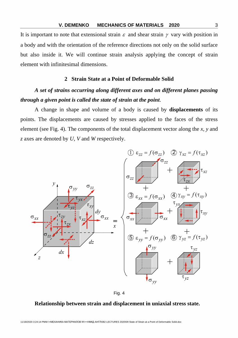
2 Strain State at a Point of Deformable Solid
A set of strains occurring along different axes and on different planes passing
through a given point is called the state of strain at the point.
A change in shape and volume of a body is caused by displacements of its
points. The displacements are caused by stresses applied to the faces of the stress
element (see Fig. 4). The components of the total displacement vector along the x, y and
z axes are denoted by U, V and W respectively.
Fig. 4
Relationship between strain and displacement in uniaxial stress state.

V. DEMENKO MECHANICS OF MATERIALS 2020
11/18/2020 3:24:14 PMW:\+МЕХАНИКА МАТЕРИАЛОВ W\++НМКД АНГЛ\082 LECTURES 2020\09 State of Strain at a Point of Deformable Solid.doc
4
In the most simple case of axial deformation illustrating on Fig. 5 first, third and
fifth components of combined stress state, shown on Fig. 4 relationship between
longitudinal strain and axial displacement is clear from Fig. 5. A-point is displaced
along x-axis with u displacement, and B-point is displaced with increment u, i.e. with
u du displacement. Elongation of AB segment is
' ' ( )A B AB dx u du u dx du . Then relative strain x equals to
xdu
dx . (3)
Fig. 5
Relationship between strain and displacement components in three-
dimensional stress state.
Consider as the plane problem a segment AB whose direction coincides with the
x axis (see Fig. 6). The distance between the points A and B is selected as infinitely
little. Denote it by dx. The components of the displacement vector at the point B differ
from those at the point A by amounts corresponding to the change in coordinate.

V. DEMENKO MECHANICS OF MATERIALS 2020
11/18/2020 3:24:14 PMW:\+МЕХАНИКА МАТЕРИАЛОВ W\++НМКД АНГЛ\082 LECTURES 2020\09 State of Strain at a Point of Deformable Solid.doc
5
Fig. 6
The increment in length of the segment AB onto x axis is U
dxx
. This increment
is the absolute elongation, i.e.:
1 1ABU
l A B AB dxx
. (4)
The ratio of the length increment of the element AB to its original length is called
longitudinal relative deformation or linear strain (relative elongation):
ABx
Udx
l Ux
AB dx x
. (5)
Similarly,
yV
y
; zW
z
. (6)
The angle of rotation of the segment AB in the xy plane is equal to the ratio of the
difference between the displacement of the points B and A along the x axis to the length
of the segment dx, i.e.,
1V
x
. (7)

V. DEMENKO MECHANICS OF MATERIALS 2020
11/18/2020 3:24:14 PMW:\+МЕХАНИКА МАТЕРИАЛОВ W\++НМКД АНГЛ\082 LECTURES 2020\09 State of Strain at a Point of Deformable Solid.doc
6
The angle of rotation of the segment AC in the xy plane is
2U
y
. (8)
The sum of the angles 1 and 2 represents the change in right angle BAC i.e.,
the angle of shear in the xy plane
yxV U
x y
. (9)
The expressions for the angles of shear in the other two coordinate planes can be
derived in a similar way.
Thus we have the following relations between displacements and strains at a
point
xU
x
; yV
y
; xW
z
;
xyU V
y x
; yzV W
z y
; zxW U
x z
. (10)
The analysis of the state of strain shows that it possesses properties closely
similar to those of the state of stress.
3 Hooke's Law
As has been established by the results of experimental tests (Figs 7–9) of
specimens made from various structural materials, there exists a direct proportionality
between normal stresses acting in cross-section and the strain , though certain
limits (Fig. 8).
This relationship, which is the principal one in mechanics of materials is called
Hooke's law and written as
E , (11)
where is normal stress, proportionality factor E is called the modulus of elasticity
(Young’s modulus); is relative elongation (strain). It is necessary to know that the
elasticity modulus is dependent on the temperature (see Fig. 10).

V. DEMENKO MECHANICS OF MATERIALS 2020
11/18/2020 3:24:14 PMW:\+МЕХАНИКА МАТЕРИАЛОВ W\++НМКД АНГЛ\082 LECTURES 2020\09 State of Strain at a Point of Deformable Solid.doc
7
Force F
Grip
Movable
crosshead
Gage
length
Grip
Test sample
(specimen)
Stationary
platen
Diameter
Fig. 7 Experimental device for material
tensile mechanical tests
Fig. 8 Stress-strain curve (diagram) showing
elastoplastic behavior of ductile material
Fig. 9 Specimens used in tensile mechanical tests
Relative elongation is
dimensionless and is often given as
percentage of the original length:
% 100%l
l
. (12)
The elastic modulus E is
measured in the same units as the stress
, i.e. in Pascals or megaPascals
2
NPa
m
. A stress of 1 Pa is very
small. 1 MPa = 106 Pa (ten to the power
of six).
The moduli of elasticity for various engineering materials are shown in Table 1.
Tangsten
Steel
Aluminium
-400 0 400 800 1200 1600
Modu
lus
of
ela
stic
ity (
GP
a)
Mod
ulu
s of
elas
ticit
y (
psi
)
Temperature ( C)°
Temperature ( K)°
400
300
200
100
0
70
60
50
40
30
20
10
0200-200 0 400 600 800
Fig. 10 Dependence of the Young’s modulus on
the temperature for different materials

V. DEMENKO MECHANICS OF MATERIALS 2020
11/18/2020 3:24:14 PMW:\+МЕХАНИКА МАТЕРИАЛОВ W\++НМКД АНГЛ\082 LECTURES 2020\09 State of Strain at a Point of Deformable Solid.doc
8
Table 1 Modulus of Elasticity Values for Various Engineering Materials (Room-
Temperature Conditions)
Material Modulus of Elasticity
GPa 106 psi
1 2 3
METALS AND METAL ALLOYS
Plain Carbon and Low Alloy Steels
Steel alloy A36 207 30
Steel alloy 1020 207 30
Steel alloy 1040 207 30
Steel alloy 4140 207 30
Steel alloy 4340 207 30
Stainless alloy 304 193 28
Stainless alloy 316 193 28
Stainless alloy 405 200 29
Stainless alloy 440A 200 29
Stainless alloy 17-7PH 204 29.5
Cast Irons
Gray irons
• Grade G1800
66-97a
9.6-14a
• Grade G3000 90-113a 13.0-16.4
a
• Grade G4000 110-138a 16-20
a
Ductile irons
• Grade 60-40-18
169
24.5
• Grade 80-55-06 168 24.4
• Grade 120-90-02 164 23.8
Aluminum Alloys
Alloy 1100 69 10
Alloy 2024 72.4 10.5
Alloy 6061 69 10
Alloy 7075 71 10.3
Alloy 356.0 72.4 10.5
Copper Alloys
C11000 (electrolytic tough pitch) 115 16.7
C17200 (beryllium-copper) 128 18.6
C26000 (cartridge brass) 110 16
C36000 (free-cutting brass) 97 14
C71500 (copper-nickel, 30%) 150 21.8
C93200 (bearing bronze) 100 14.5
Magnesium Alloys
Alloy AZ31B 45 6.5
Alloy AZ91D 45 6.5
Titanium Alloys
Commercially pure (ASTM grade 1) 103 14.9
Alloy Ti-5Al-2.5Sn 110 16

V. DEMENKO MECHANICS OF MATERIALS 2020
11/18/2020 3:24:14 PMW:\+МЕХАНИКА МАТЕРИАЛОВ W\++НМКД АНГЛ\082 LECTURES 2020\09 State of Strain at a Point of Deformable Solid.doc
9
Alloy Ti-6Al-4V 114 16.5
Precious Metals
Gold (commercially pure) 77 11.2
Platinum (commercially pure) 171 24.8
Silver (commercially pure) 74 10.7
Refractory Metals
Molybdenum (commercially pure) 320 46.4
Tantalum (commercially pure) 185 27
Tungsten (commercially pure) 400 58
Miscellaneous Nonferrous Alloys
Nickel 200 204 29.6
Inconel 625 207 30
Monel 400 180 26
Haynes alloy 25 236 34.2
Invar 141 20.5
Super invar 144 21
Kovar 207 30
Chemical lead 13.5 2
Tin (commercially pure) 44.3 6.4
Lead-Tin solder (60Sn-40Pb) 30 4.4
Zinc (commercially pure) 104.5 15.2
Zirconium, reactor grade 702 99.3 14.4
GRAPHITE, CERAMICS, AND
SEMICONDUCTING MATERIALS
Aluminum oxide
• 99.9% pure
380
55
• 96% 303 44
• 90% 275 40
Concrete 25.4-36.6a 3.7-5.3
a
Diamond
• Natural
700-1200
102-174
• Synthetic 800-925 116-134
Gallium arsenide, single crystal
• In the (100) direction
85 12.3
• In the (110) direction 122 17.7
• In the (111) direction 142 20.6
Glass, borosilicate (Pyrex) 70 10.1
Glass, soda-lime 69 10
Glass ceramic (Pyroceram) 120 17.4
Graphite
• Extruded 11 1.6
• Isostatically molded 11.7 1.7
Silica, fused 73 10.6
Silicon, single crystal

V. DEMENKO MECHANICS OF MATERIALS 2020
11/18/2020 3:24:14 PMW:\+МЕХАНИКА МАТЕРИАЛОВ W\++НМКД АНГЛ\082 LECTURES 2020\09 State of Strain at a Point of Deformable Solid.doc
10
• In the (100) direction 129 18.7
• In the (110) direction 168 24.4
• In the (111) direction 187 27.1
Silicon carbide
• Hot pressed
207-483
30-70
• Sintered 207-483 30-70
Silicon nitride
• Hot pressed
304
44.1
• Reaction bonded 304 44.1
• Sintered 304 44.1
Zirconia, 3 mol% Y2O3 205 30
POLYMERS
Elastomers
• Butadiene-acrylonitrile (nitrile)
0.0034b 0.00049
b
• Styrene-butadiene (SBR) 0.002-0.010b 0.0003-0.0015
b
Epoxy 2.41 0.35
Nylon 6,6 1.59-3.79 0.230-0.550
Phenolic 2.76-4.83 0.40-0.70
Polybutylene terephthalate (PBT) 1.93-3.00 0.280-0.435
Polycarbonate (PC) 2.38 0.345
Polyester (thermoset) 2.06-4.41 0.30-0.64
Polyetheretherketone (PEEK) 1.10 0.16
Polyethylene
• Low density (LDPE)
0.172-0.282
0.025-0.041
• High density (HDPE) 1.08 0.157
• Ultrahigh molecular weight (UHMWPE) 0.69 0.100
Polyethylene terephthalate (PET) 2.76-4.14 0.40-0.60
Polymethyl methacrylate (PMMA) 2.24-3.24 0.325-0.470
Polypropylene (PP) 1.14-1.55 0.165-0.225
Polystyrene (PS) 2.28-3.28 0.330-0.475
Polytetrafluoroethylene (PTFE) 0.40-0.55 0.058-0.080
Polyvinyl chloride (PVC) 2.41-4.14 0.35-0.60
FIBER MATERIALS
Aramid (Kevlar 49) 131 19
Carbon (PAN precursor)
• Standard modulus
230
33.4
• Intermediate modulus 285 41.3
• High modulus 400 58
E Glass 72.5 10.5
COMPOSITE MATERIALS
Aramid fibers-epoxy matrix ( 0.60fV )
Longitudinal
76
11

V. DEMENKO MECHANICS OF MATERIALS 2020
11/18/2020 3:24:14 PMW:\+МЕХАНИКА МАТЕРИАЛОВ W\++НМКД АНГЛ\082 LECTURES 2020\09 State of Strain at a Point of Deformable Solid.doc
11
Transverse 5.5 0.8
High modulus carbon fibers-epoxy matrix ( 0.60fV )
Longitudinal 220 32
Transverse 6.9 1.0
E glass fibers-epoxy matrix ( 0.60fV )
Longitudinal 45 6.5
Transverse 12 1.8
Wood
• Douglas fir (12% moisture)
Parallel to grain
10.8-13.6c
1.57-1.97c
Perpendicular to grain 0.54-0.68c 0.078-0.10
c
• Red oak (12% moisture)
Parallel to grain
11.0-14.1c
1.60-2.04c
Perpendicular to grain 0.55-0.71c 0.08-0.10
c
a Secant modulus taken at 25% of ultimate strength.
b Modulus taken at 100% elongation.
c Measured in bending.
4 Lateral Strain. Poisson's Ratio
Experiments show that (within elasticity limits) the extension of a bar in the
longitudinal direction is accompanied by its proportional contraction in the lateral
direction (Fig. 11).
Fig. 11 Unidirectional tension of stress element and corresponding contraction of its edges in
its lateral directions.

V. DEMENKO MECHANICS OF MATERIALS 2020
11/18/2020 3:24:14 PMW:\+МЕХАНИКА МАТЕРИАЛОВ W\++НМКД АНГЛ\082 LECTURES 2020\09 State of Strain at a Point of Deformable Solid.doc
12
If we consider x-direction then
,
,
.
long x
lat y
lat z
dx dx dx dx
dx dx
dy dy dy dy
dy dy
dz dz dz dz
dz dz
(13)
As experiments show,
lat long or (14)
,
.
y x
z x
(15)
where
lat
long
. (16)
The absolute magnitude of this ratio is called the Poisson's ratio.
The quantity characterizes the properties of a material and is determined
experimentally. The numerical values of lie within the limits from 0.25 … 0.35 for all
metals and alloys. Poisson’s ratio values for various engineering materials are shown in
Table 2.
Table 2 Poisson's Ratio Values for Various Engineering Materials (Room-
Temperature Conditions)
Material Poisson’s
Ratio Material
Poisson's
Ratio
1 2 3 4
METALS AND METAL ALLOY
Plain Carbon and Low Alloy Steels
Refractory Metals
Molybdenum (commercially pure) 0.32
Steel alloy A36 0.30
Steel alloy 1020 0.30 Tantalum (commercially pure) 0.35
Steel alloy 1040 0.30
Steel alloy 4140 0.30 Tungsten (commercially pure) 0.28

V. DEMENKO MECHANICS OF MATERIALS 2020
11/18/2020 3:24:14 PMW:\+МЕХАНИКА МАТЕРИАЛОВ W\++НМКД АНГЛ\082 LECTURES 2020\09 State of Strain at a Point of Deformable Solid.doc
13
Steel alloy 4340 0.30
Stainless Steels Miscellaneous Nonferrous Alloys
Stainless alloy 304 0.30 Nickel 200 0.31
Stainless alloy 316 0.30 Inconel 625 0.31
Stainless alloy 405 0.30 Monel 400 0.32
Stainless alloy 440A 0.30 Chemical lead 0.44
Stainless alloy 17-7PH 0.30 Tin (commercially pure) 0.33
Cast Irons Zinc (commercially pure) 0.25
Gray irons
• Grade G1800
0.26
Zirconium, reactor grade 702 0.35
GRAPHITE, CERAMICS, AND
SEMICONDUCTING MATERIALS • Grade G3000 0.26
• Grade G4000 0.26 Aluminum oxide
Ductile irons • 99.9% pure 0.22
• Grade 60-40-18 0.29 • 96% 0.21
• Grade 80-55-06 0.31 • 90% 0.22
• Grade 120-90-02 0.28 Concrete 0.20
Aluminum Alloys Diamond
Alloy 1100 0.33 • Natural 0.10-0.30
Alloy 2024 0.33
Alloy 6061 0.33 • Synthetic 0.20
Alloy 7075 0.33 Gallium arsenide
• (100) orientation
0.30 Alloy 356.0 0.33
Copper Alloys Glass, borosilicate (Pyrex) 0.20
C11000 (electrolytic tough pitch) 0.33 Glass, soda-lime 0.23
Glass ceramic (Pyroceram) 0.25
C17200 (beryllium-copper) 0.30 Silica, fused 0.17
C26000 (cartridge brass) 0.35 Silicon
C36000 (free-cutting brass) 0.34 • (100) orientation 0.28
C71500 (copper-nickel, 30%) 0.34 • (111) orientation 0.36
C93200 (bearing bronze) 0.34 Silicon carbide
Magnesium Alloys • Hot pressed 0.17
Alloy AZ31B 0.35 • Sintered 0.16
Alloy AZ91D 0.35 Silicon nitride
Titanium Alloys • Hot pressed 0.30
Commercially pure (ASTM grade 1) 0.34 • Reaction bonded 0.22
• Sintered 0.28
Alloy Ti-5Al-2.5Sn 0.34 Zirconia, 3 mol% Y2O3 0.31
Alloy Ti-6Al-4V 0.34 POLYMERS
Precious Metals Nylon 6,6 0.39
Gold (commercially pure) 0.42 Polycarbonate (PC) 0.36
Platinum (commercially pure) 0.39 Polystyrene (PS) 0.33
Polytetrafluoroethylene (PTFE) 0.46

V. DEMENKO MECHANICS OF MATERIALS 2020
11/18/2020 3:24:14 PMW:\+МЕХАНИКА МАТЕРИАЛОВ W\++НМКД АНГЛ\082 LECTURES 2020\09 State of Strain at a Point of Deformable Solid.doc
14
Silver (commercially pure) 0.37
COMPOSITE MATERIALS Polyvinyl chloride (PVC) 0.38
Aramid fibers-epoxy matrix
( 0.6fV )
0.34 FIBER MATERIALS
E Glass 0.22
High modulus carbon fibers-epoxy
matrix ( 0.6fV )
0.25 E glass fibers-epoxy matrix
( 0.6fV )
0.19
5 Generalized Hooke's Law for three dimensional stress-strain state
Fig. 12 Fig. 13
Generalized Hooke’s law represents the equations which connect components of
stress and strain states. To write these equations, we will consider the stress element
under the principal stresses loading (see Figs 12, 13). Our goal will be in finding the
relative elongations (strains) of three mutually perpendicular edges along x, y, z axes.
They will be denoted as x , y , z (x, y, z directions are principal).
Given: x , y , z , , E.
It is required to determine the quantities x , y , z .
Let’s note one more that the x, y and z axes coincide with the principal axes. The
relative elongation (linear strain) in the direction of the x axis due to the stress x is
x E .

V. DEMENKO MECHANICS OF MATERIALS 2020
11/18/2020 3:24:14 PMW:\+МЕХАНИКА МАТЕРИАЛОВ W\++НМКД АНГЛ\082 LECTURES 2020\09 State of Strain at a Point of Deformable Solid.doc
15
The stresses y and z produce elongations of opposite sign (lateral) along the
x axis which are equal to y
E
and z
E
. Consequently, total relative elongation
(strain) with respect to the x axis
yx zx
E E E
. (17)
Similar expressions are obtained by analogy for y and z . Thus
1,
1,
1.
x x y zE
y y x zE
z z y xE
(18)
If the x, y and z axes don't coincide with the principal ones, then we will have
1,
1,
1.
x x y zE
y y x zE
z z y xE
(19)
but six additional relationships, connecting shear stresses and angular strains it is
necessary to add in this case.
6 Relative Change of Volume (Unit Volume Change)
The initial volume of any infinitesimally small element before deformation
(see Fig. 14):
0dV dxdydz . (20)
After deformation, the lengths of the element
increase to dx dx , dy dy and dz dz
(see Fig. 14). Thus, the volume of the element
after deformation is
dV dx dx dy dy dz dz . (21)
The relative change of the volume (unit
volume change)
Fig. 14

V. DEMENKO MECHANICS OF MATERIALS 2020
11/18/2020 3:24:14 PMW:\+МЕХАНИКА МАТЕРИАЛОВ W\++НМКД АНГЛ\082 LECTURES 2020\09 State of Strain at a Point of Deformable Solid.doc
16
0
0 0
1 1VdV dV dV dx dx dy dy dz dz
edV dV dx dy dz
1 1 1 1 1 1 1x y z y x xy z
1 1 .z y y z x x z x y x y z x y z
In result,
V x y ze . (22)
Substituting expressions (17) into formula (20), we find
1 1
V x y z y x zeE E
1 1 2
z x y x y zE E
,
1 2V x y ze
E
, (23)
or
1 2 31 2
VeE
(24)
in terms of principal stresses.
7 Hook’s Law in Shear
Suppose now that there is a state
of stress in which the faces of an
isolated element are only acted on by
shearing stresses (see Fig. 15). Such
a state of stress is called pure shear.
Principal stresses and directions in
pure shear are situated at 45 relative
to directions of shear (see Fig. 16).
Principal stresses are equal 1 yz
(in OA direction), 2 0 , 3 yz .
Fig. 15

V. DEMENKO MECHANICS OF MATERIALS 2020
11/18/2020 3:24:14 PMW:\+МЕХАНИКА МАТЕРИАЛОВ W\++НМКД АНГЛ\082 LECTURES 2020\09 State of Strain at a Point of Deformable Solid.doc
17
Fig. 16
It is seen from Fig. 15, that the quantity S is absolute shear.
Let us calculate relative angle of shear:
tg yz yzS
a
. (25)
This relationship is valid because S a . Principal linear strain along OA
direction is
11
l
OA
. (26)
Because
1 cos452
Sl S
, (27)
and
2OA a , (28)
we found that
11 1
22 2
S S
aa
. (29)
Substituting (25) in (29) is resulted in
11
2xy . (30)
Otherwise, let us find the relative elongation 1 from generalized Hooke’s law for pure
shear deformation ( 1 yz , 2 0 , 3 yz ):

V. DEMENKO MECHANICS OF MATERIALS 2020
11/18/2020 3:24:14 PMW:\+МЕХАНИКА МАТЕРИАЛОВ W\++НМКД АНГЛ\082 LECTURES 2020\09 State of Strain at a Point of Deformable Solid.doc
18
1 1 2 31 1
yzE E
, (31)
Equating (30) and (31)
1 1
2yz yz
E
,
2 1yz yz
E
,
where proportionality factor
2 1
EG
(32)
is called modulus in shear (shear modulus)
Finally, we have
yz yzG . (33)
This relationship is called Hook's law in shear.
8 Strain Energy and Strain Energy Density
Strain energy is a fundamental concept in applied mechanics, and strain-energy
principles are widely used for determining the response of machines and structures to
loads. Now we introduce the subject of strain energy in its simplest form by
considering only axially loaded members subjected to static loads.
To illustrate the basic ideas, let us consider a prismatic bar subjected to a tensile
force (see Fig. 17). We assume that the load is applied slowly, so that is gradually
increases from 0 to its maximum value P. Such a load is called a static load because
there are no dynamic or inertial effects due to motion. The bar gradually elongates as
the load is applied, eventually reaching its maximum elongation at the same time
that the load reaches its full value P. There after, the load and elongation remain
unchanged.

V. DEMENKO MECHANICS OF MATERIALS 2020
11/18/2020 3:24:14 PMW:\+МЕХАНИКА МАТЕРИАЛОВ W\++НМКД АНГЛ\082 LECTURES 2020\09 State of Strain at a Point of Deformable Solid.doc
19
During the loading, the load P
moves slowly through the distance and
does a certain amount of work. To
evaluate this work, we recall from
elementary mechanics that a constant force
does work equal to the product of the force
at the distance through which it moves.
However, in our case the force varies in
magnitude from 0 to its maximum value
P. To find the work done by the load under
these conditions, we need to know the
manner in which the force varies. This
information is supplied by a load-displacement diagram, which is plotted for linearly
elastic material in Fig. 18. On this diagram the vertical axis represents the axial load
and the horizontal axis represents the corresponding elongation of the bar.
The work done by the load is
represented in the figure by the area of
the shaded strip below the load-
displacement curve. In geometric terms,
the work done by the load is equal to
the area below the load-displacement
curve.
When the load stretches the bar,
strains are produced. The presence of
these strains increases the energy level of
the bar itself. Therefore, a new quantity,
called strain energy, is defined as the
Fig. 17 Prismatic bar subjected to a statically
applied load
PA
P
O
B
2
PU
Fig. 18 Load-displacement diagram for a bar of
linearly elastic material.

V. DEMENKO MECHANICS OF MATERIALS 2020
11/18/2020 3:24:14 PMW:\+МЕХАНИКА МАТЕРИАЛОВ W\++НМКД АНГЛ\082 LECTURES 2020\09 State of Strain at a Point of Deformable Solid.doc
20
energy absorbed by the bar during the loading process. From the principle of
conservation of energy, we know that this strain energy is equal to the work done by
the load provided no energy is added or subtracted in the form of heat. Therefore,
2
PU W
(34)
in which U is the symbol of strain energy, W is symbol of work. Sometimes strain
energy is referred to as internal work to distinguish it from the external work done by
the load.
In Fig. 18, strain energy is the area of the shaded triangle OAB. The principle that
the work of the external loads is equal to the strain energy for the case of linearly
elastic behavior was first stated by the French engineer B.P.E. Clapeyron and is known
as Clapeyron theorem.
Since Hooke’s law establishes linear relationship between the load and
elongation or between the stress and strain in linearly elastic material, elongation of the
bar 0l l l is given by the equation
PL
EA , (35)
Because /P A , 0/l l , E .
Combining this equation with Eq. 34 enables us to express the strain energy for a
linearly elastic bar in the following form
2
2
P LU
EA . (36)
In many situations it is convenient to use a quantity called strain-energy
density, defined as the strain energy per unit volume of material. Expressions for
strain-energy density in the case of linearly elastic materials can be obtained from the
formula for strain energy of a prismatic bar (Eq. 36). Since the strain energy of the bar
is distributed uniformly throughout its volume, we can determine the strain-energy
density by dividing the total strain energy U by the volume AL of the bar. Thus, the
strain-energy density, denoted by the symbol 0U , can be expressed in the form

V. DEMENKO MECHANICS OF MATERIALS 2020
11/18/2020 3:24:14 PMW:\+МЕХАНИКА МАТЕРИАЛОВ W\++НМКД АНГЛ\082 LECTURES 2020\09 State of Strain at a Point of Deformable Solid.doc
21
2
0 22
PU
EA . (37)
If we replace /P A by the stress , we get
2
01
2 2U
E
. (38)
This equation give the strain-energy density in a linearly elastic material in terms of the
normal stress and the normal strain . This equation corresponds to uniaxial stress
state at a point of the bar.
The strain-energy stored in an elementary volume of elastic solid in its
deformation in three-dimensional stress-state is determined by the total work done by
the internal forces distributed over the surface of this stress element. The normal force
xdydz does work on the displacement xdx dx (see Fig. 13). This work of internal
elastic force is given by formula
1 1( )
2 2x x x x
dxdx dydz dxdydz
dx
, (39)
where x is the strain along the x axis.
Similar expressions are obtained for the work done by two other normal
components: 1
2y ydzdx dy ;
1
2z zdxdy dz .
Then total strain energy stored in an
elementary volume dxdydz (see Fig. 19) is:
1
2x x y y z zdU dxdydz .
(40)
For this stress element, strain-energy density
01
2x x y y z z
dUU
dV . (41)
Let’s express strains in terms of stresses by generalized Hook’s law:
Fig. 19

V. DEMENKO MECHANICS OF MATERIALS 2020
11/18/2020 3:24:14 PMW:\+МЕХАНИКА МАТЕРИАЛОВ W\++НМКД АНГЛ\082 LECTURES 2020\09 State of Strain at a Point of Deformable Solid.doc
22
1,
1,
1.
x x y z
y y x z
z z x y
E
E
E
(42)
Then
2 2 20
12
2x y z x y y z z xU
E
. (43)
Conclusion. Strain energy describes the possibility of elastic solid to change its shape
and also volume in deformation.
Example 1. Elastic aluminum block R is confined between plane parallel walls of
absolutely rigid block S (see Fig. 20). A uniformly distributed pressure p is applied to
the top of the block by a resultant force F. Disregarding friction between the blocks
find stresses on the R block faces and strains of its edges. Calculate also its relative
change in volume (dilatation).
Given: block R dimensions: 21 1 1 10 m. Its mechanical properties: 70E GPa,
0.3 . Pressure 60p MPa.
Fig. 20

V. DEMENKO MECHANICS OF MATERIALS 2020
11/18/2020 3:24:14 PMW:\+МЕХАНИКА МАТЕРИАЛОВ W\++НМКД АНГЛ\082 LECTURES 2020\09 State of Strain at a Point of Deformable Solid.doc
23
Due to disregarding friction, elastic block will be under principal stresses. Its
stress state may be described by Fig. 21. It is
evident that 60z MPa, 0y , 0x ,
0z , 0y , 0x .
Three unknown components of stress–strain
state we will determine using the equations of
generalized Hooke’s law (19):
1,
1,
1,
x x y zE
y y x zE
z z y xE
or for our case (in MPa):
3
3
3
10 0.3 60 ,
70 101
0 0.3 0 60 ,70 101
60 0.3 0 .70 10
x y
y y
z y
In result of solution we get
18y MPa, 333.4 10x , 378 10z
.
Relative change in volume is
3 333.4 0 78 10 44.6 10Ve (volume decreases).
Strain energy density is determined by formula (43):
2 2 20 1 2 3 1 2 2 3 3 1
12
2U
E
.
In our case of loading (in MPa):
2 2 30 3
10 ( 18) ( 60) 0.6(0 ( 18) ( 60) 0) 65.3 10
2 70 10U
G/m
3.
Fig. 21

V. DEMENKO MECHANICS OF MATERIALS 2020
11/18/2020 3:24:14 PMW:\+МЕХАНИКА МАТЕРИАЛОВ W\++НМКД АНГЛ\082 LECTURES 2020\09 State of Strain at a Point of Deformable Solid.doc
24
Example 2 An elastic aluminum block R with dimensions 21 1 1 10 m (Fig. 22)
is compressed inside of an absolutely rigid array by the force F that applies a uniformly
distributed pressure to the block equals to 60 MPa. Its elastic properties are 70E GPа,
0.3 . Determine stresses on the R block faces and strains of its edges. Calculate also
its relative change in volume (dilatation) and strain energy density.
Fig. 22
Solution.
Disregarding friction between the block and array
stress state of the R block may be described by
Fig. 23. It is evident that 60z MPa,
0x y , 0x y .
Three unknown components of stress-strain state
we will determine using the equations of
generalized Hooke’s law (19):
1,
1,
1,
x x y zE
y y x zE
z z y xE
or for our case (in MPa):
Fig. 23

V. DEMENKO MECHANICS OF MATERIALS 2020
11/18/2020 3:24:14 PMW:\+МЕХАНИКА МАТЕРИАЛОВ W\++НМКД АНГЛ\082 LECTURES 2020\09 State of Strain at a Point of Deformable Solid.doc
25
3
3
3
10 0.3 60 ,
70 10
10 0.3 60 ,
70 10
160 0.3 .
70 10
x x y
y y x
z x y
In result of solution we get 25.7y x MPa, 364 10z ,
Unit volume change
3 30
0
0 0 64 10 64 10V x y zV V
eV
(volume decreases).
Strain energy density is determined by formula (43).
In our case of loading 0 3
1
2 70 10U
2 2 2( 25.7) ( 25.7) ( 60) 2 0.3 ( 25.7) ( 25.7) ( 25.7) ( 60) ( 60) ( 25.7)
338 10 G/m3.