lecture basic of video technology psycho-optic · lecture basic of video technology psycho-optic...
TRANSCRIPT
Lecture basic of video technologyPsycho-Optic
-History: different levels of abstraction
- Figure 3-D onto 2-D- First graphics/drawings, cave paining
- Decomposition in pixels: Photocells, parallel transmission- Decomposition in temporal successive pixels (sampling), or images for moving images (B/W TV)
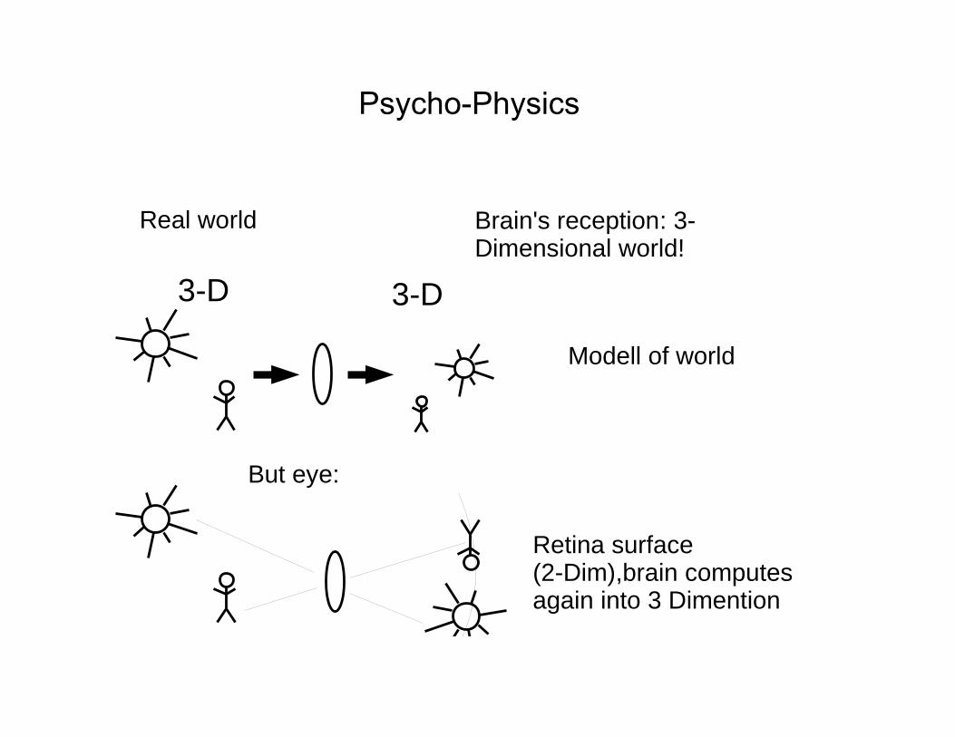
Psycho-Physics
3-D 3-D
Real world Brain's reception: 3-Dimensional world!
Modell of world
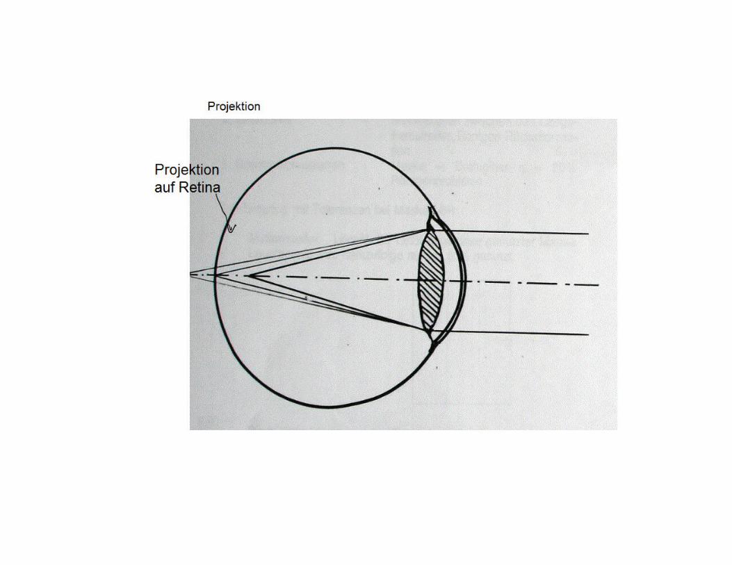
But eye:
Retina surface (2-Dim),brain computes again into 3 Dimention
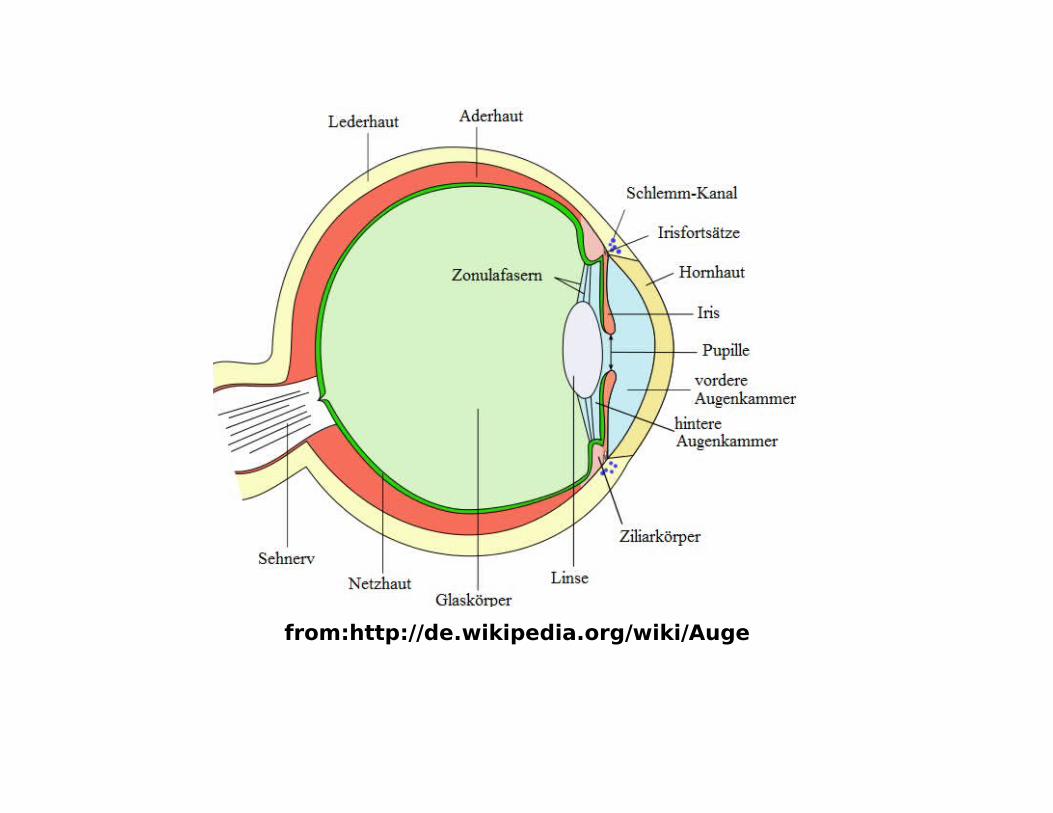
from:http://de.wikipedia.org/wiki/Auge
Projection matrix
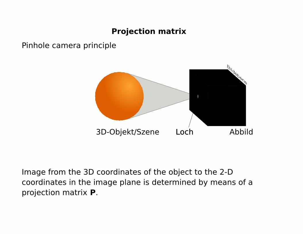
Pinhole camera principle
Image from the 3D coordinates of the object to the 2-D coordinates in the image plane is determined by means of a projection matrix P.
AbbildLochLoch3D-Objekt/Szene
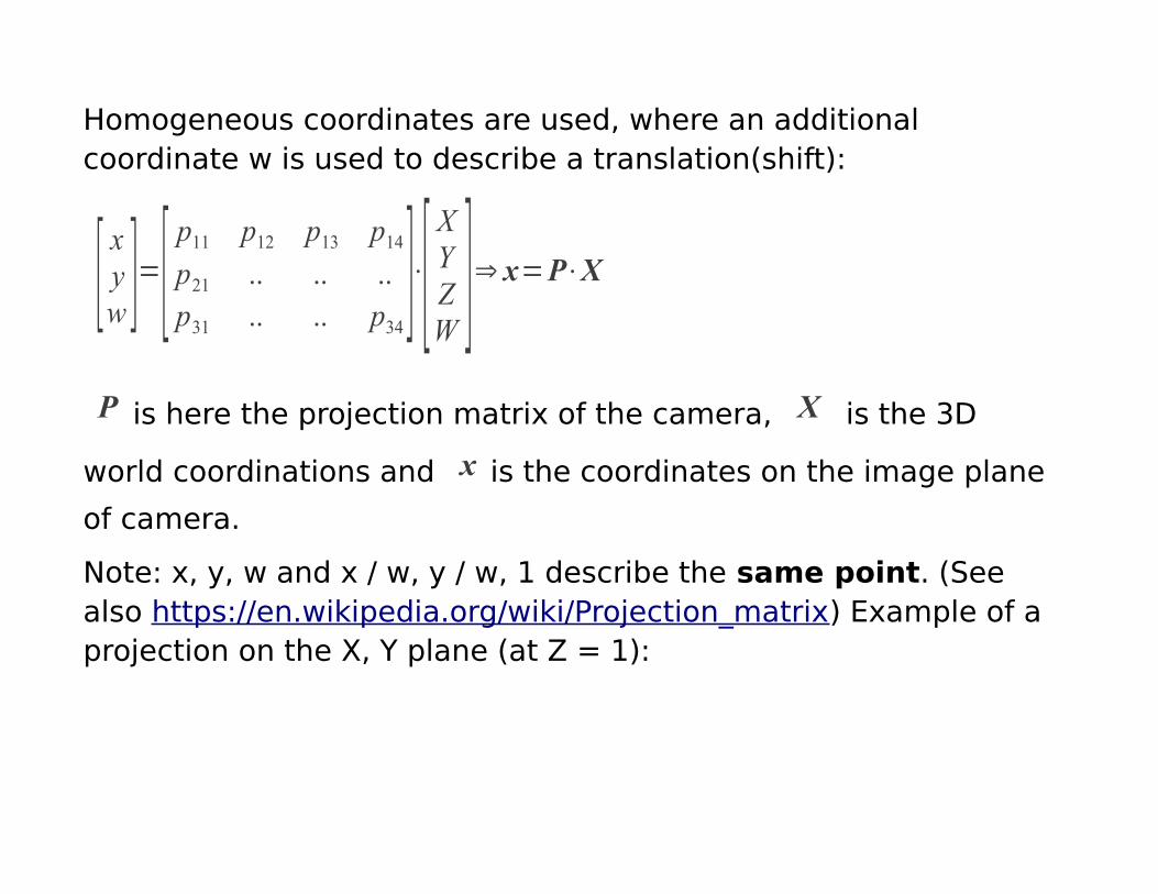
Homogeneous coordinates are used, where an additional coordinate w is used to describe a translation(shift):
[xyw ]=[
p11 p12 p13 p14p21 .. .. ..p31 .. .. p34
]⋅[XYZW
]⇒ x=P⋅XP is here the projection matrix of the camera, X is the 3D
world coordinations and x is the coordinates on the image plane
of camera.
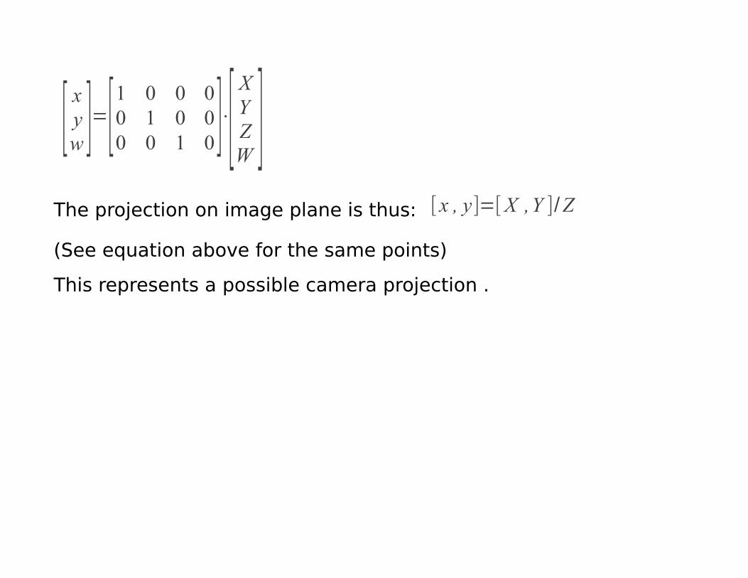
Note: x, y, w and x / w, y / w, 1 describe the same point. (See also https://en.wikipedia.org/wiki/Projection_matrix) Example of a projection on the X, Y plane (at Z = 1):
[xyw ]=[
1 0 0 00 1 0 00 0 1 0]⋅[
XYZW
]The projection on image plane is thus: [x , y]=[X ,Y ]/Z
(See equation above for the same points)
This represents a possible camera projection .

By normalization to Z=1, we perform a projection on the image plane at Z=1 .
x
z
z=1
z=0
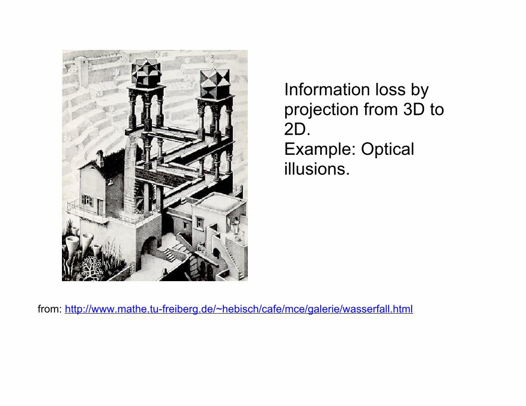
from: http://www.mathe.tu-freiberg.de/~hebisch/cafe/mce/galerie/wasserfall.html
Information loss by projection from 3D to 2D.Example: Optical illusions.
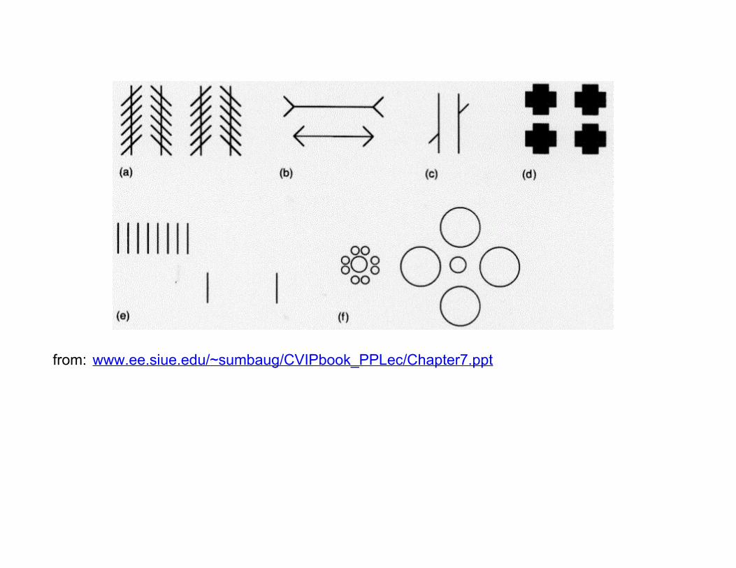
from: www.ee.siue.edu/~sumbaug/CVIPbook_PPLec/Chapter7.ppt
Decomposition into pixels
Important here: The brain recognizes partly hidden objects, so also hidden from the grid of the point grid
- The eye itself perceives images with individual visual cells, and composes images from them.
How do visual cells look, how many and which forms are there?
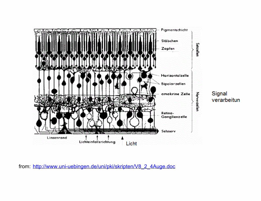
from: http://www.uni-uebingen.de/uni/pki/skripten/V8_2_4Auge.doc
-2 Types of photoreceptors: rods and cones:
-Rods: approx. 120 million rods, light-dark vision (scotopic vision).-Cones: approx. 6 million pins, in the so-called Yellow spot (macula lutea), color vision in daylight (photopic vision)
Difference of number important for transmission andCompression.
from: http://de.wikipedia.org/wiki/Photorezeptor

from: http://www-itiv.etec.uni-karlsruhe.de/opencms/de/research/workgroups/MST_Optik/ophthalmo/IOL_Test/imaging_quality.html
± 1 degree: greatest concentration
Blindspot
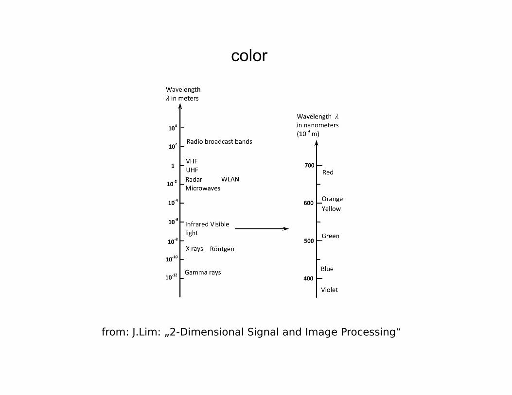
color
from: J.Lim: „2-Dimensional Signal and Image Processing“
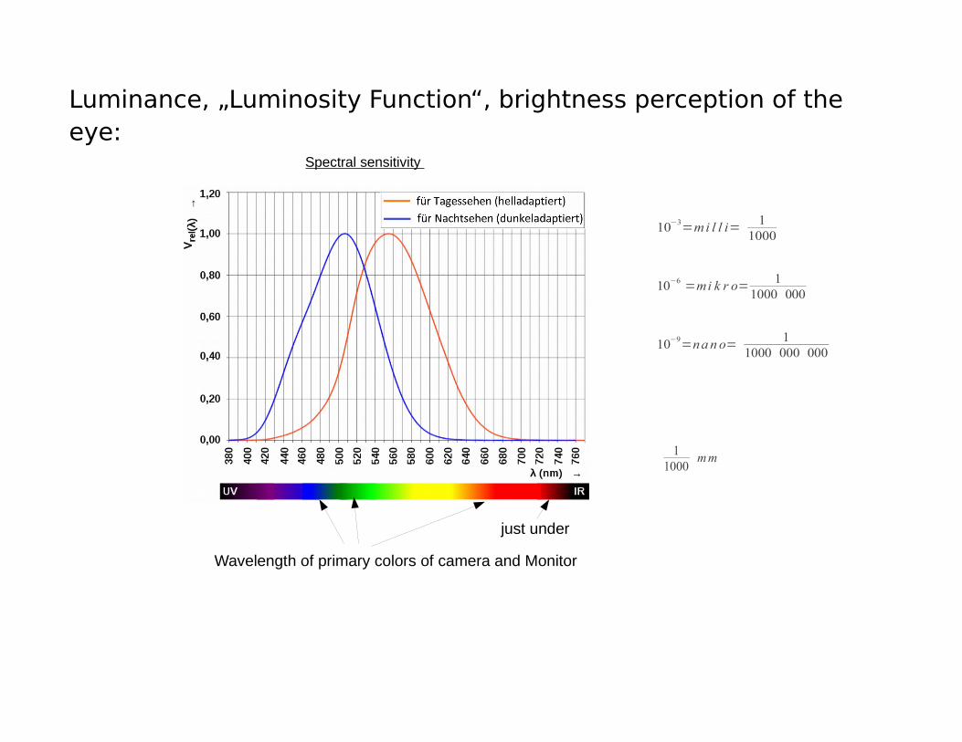
Luminance, „Luminosity Function“, brightness perception of the eye:
11000
mm
Spectral sensitivity
Wavelength of primary colors of camera and Monitor
just under
10−3=mi l l i= 11000
10−6 =mi k r o= 1
1000 000
10−9=nan o= 11000 000 000
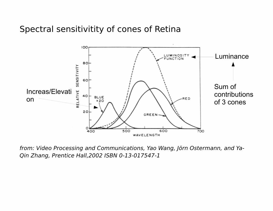
Spectral sensitivitity of cones of Retina
from: Video Processing and Communications, Yao Wang, Jörn Ostermann, and Ya-Qin Zhang, Prentice Hall,2002 ISBN 0-13-017547-1
Increas/Elevation
Luminance
Sum of contributions of 3 cones
Note: In the "Luminosity Function" we see quantitatively the different sensitivity of the eye for different wave lengths of the light. Cameras and monitors have their centers of their transmission areas of the primary color filters or the primary colors dyes of the monitors at the marked locations of the previous picture. There we can see the corresponding sensibility of the eye.
In addition, monitors and also cameras have a non-linear luminous or sensitivity characteristic, which is somewhat exponential (slower light rise with low control, fast increase with stronger control).
The combination of eye sensitivity and the non-linearity of the monitors results in the factors of the luminance component of image Y, which can easily be viewed as a black / white version of the color image (our virtual rods):
Y :=0.299R+0.587G+0.114B
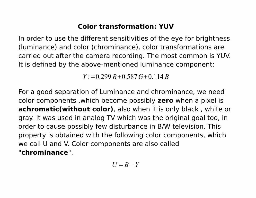
Color transformation: YUV
In order to use the different sensitivities of the eye for brightness (luminance) and color (chrominance), color transformations are carried out after the camera recording. The most common is YUV. It is defined by the above-mentioned luminance component:
Y :=0.299R+0.587G+0.114B
For a good separation of Luminance and chrominance, we need color components ,which become possibly zero when a pixel is achromatic(without color), also when it is only black , white orgray. It was used in analog TV which was the original goal too, in order to cause possibly few disturbance in B/W television. This property is obtained with the following color components, which we call U and V. Color components are also called "chrominance".
U=B−Y
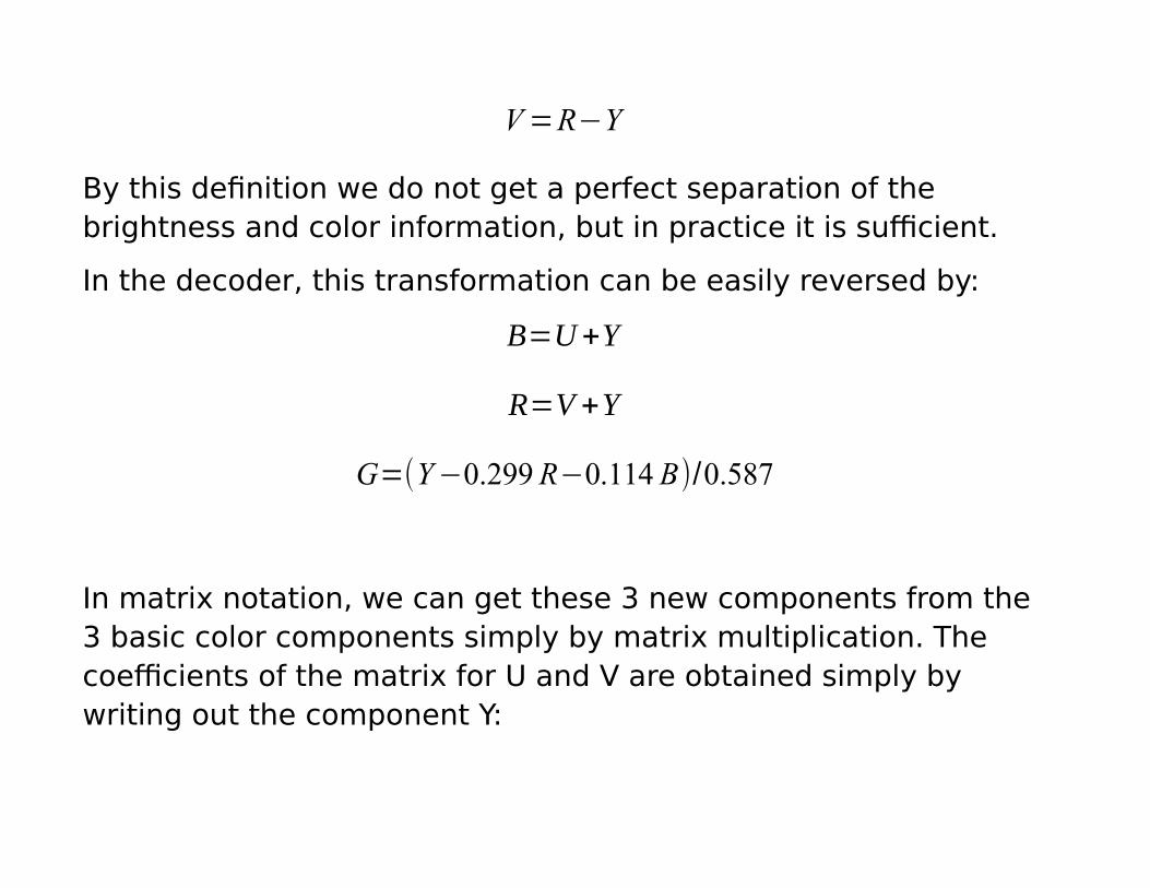
V=R−Y
By this definition we do not get a perfect separation of the brightness and color information, but in practice it is sufficient.
In the decoder, this transformation can be easily reversed by:
B=U+Y
R=V +Y
G=(Y−0.299R−0.114 B)/0.587
In matrix notation, we can get these 3 new components from the 3 basic color components simply by matrix multiplication. The coefficients of the matrix for U and V are obtained simply by writing out the component Y:
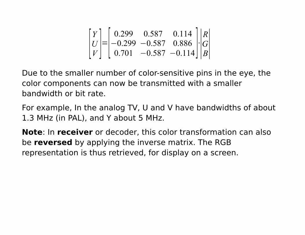
[YUV ]=[
0.299 0.587 0.114−0.299 −0.587 0.8860.701 −0.587 −0.114]⋅∣
RGB∣
Due to the smaller number of color-sensitive pins in the eye, the color components can now be transmitted with a smaller bandwidth or bit rate.
For example, In the analog TV, U and V have bandwidths of about1.3 MHz (in PAL), and Y about 5 MHz.
Note: In receiver or decoder, this color transformation can also be reversed by applying the inverse matrix. The RGB representation is thus retrieved, for display on a screen.
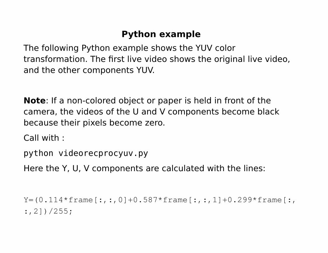
Python example
The following Python example shows the YUV color transformation. The first live video shows the original live video, and the other components YUV.
Note: If a non-colored object or paper is held in front of the camera, the videos of the U and V components become black because their pixels become zero.
Call with :
python videorecprocyuv.py
Here the Y, U, V components are calculated with the lines:
Y=(0.114*frame[:,:,0]+0.587*frame[:,:,1]+0.299*frame[:,:,2])/255;
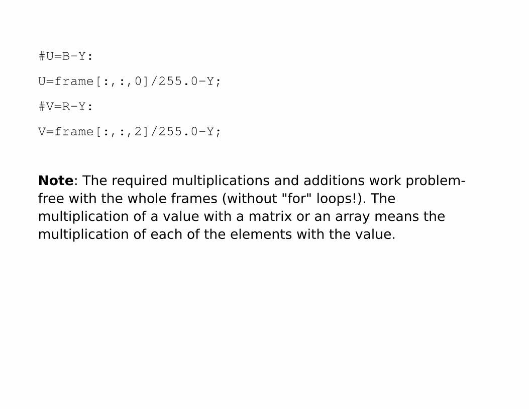
#U=B-Y:
U=frame[:,:,0]/255.0-Y;
#V=R-Y:
V=frame[:,:,2]/255.0-Y;
Note: The required multiplications and additions work problem-free with the whole frames (without "for" loops!). The multiplication of a value with a matrix or an array means the multiplication of each of the elements with the value.
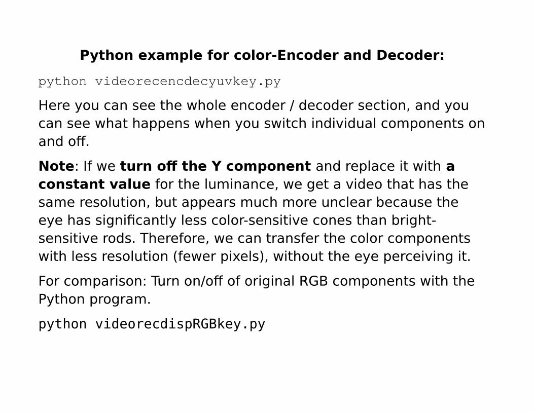
Python example for color-Encoder and Decoder:
python videorecencdecyuvkey.py
Here you can see the whole encoder / decoder section, and you can see what happens when you switch individual components onand off.
Note: If we turn off the Y component and replace it with a constant value for the luminance, we get a video that has the same resolution, but appears much more unclear because the eye has significantly less color-sensitive cones than bright-sensitive rods. Therefore, we can transfer the color components with less resolution (fewer pixels), without the eye perceiving it.
For comparison: Turn on/off of original RGB components with the Python program.
python videorecdispRGBkey.py
Note: Even if we consider only single color component R.G, or B, we perceive the video sharply in full spatial resolution because each of these color components also has different brightness sequences.
For this reason, the transformation is performed according to YUV(or YIQ).
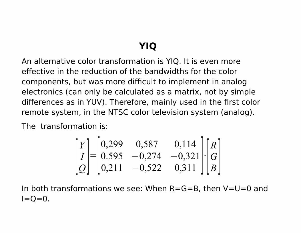
YIQ
An alternative color transformation is YIQ. It is even more effective in the reduction of the bandwidths for the color components, but was more difficult to implement in analog electronics (can only be calculated as a matrix, not by simple differences as in YUV). Therefore, mainly used in the first color remote system, in the NTSC color television system (analog).
The transformation is:
[YIQ]=[
0,299 0,587 0,1140.595 −0,274 −0,3210,211 −0,522 0,311 ]⋅[
RGB ]
In both transformations we see: When R=G=B, then V=U=0 and I=Q=0.
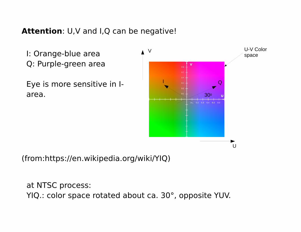
Attention: U,V and I,Q can be negative!
(from:https://en.wikipedia.org/wiki/YIQ)
at NTSC process:YIQ.: color space rotated about ca. 30°, opposite YUV.
I: Orange-blue areaQ: Purple-green area
Eye is more sensitive in I-area.
QI
300
V
U
U-V Color space
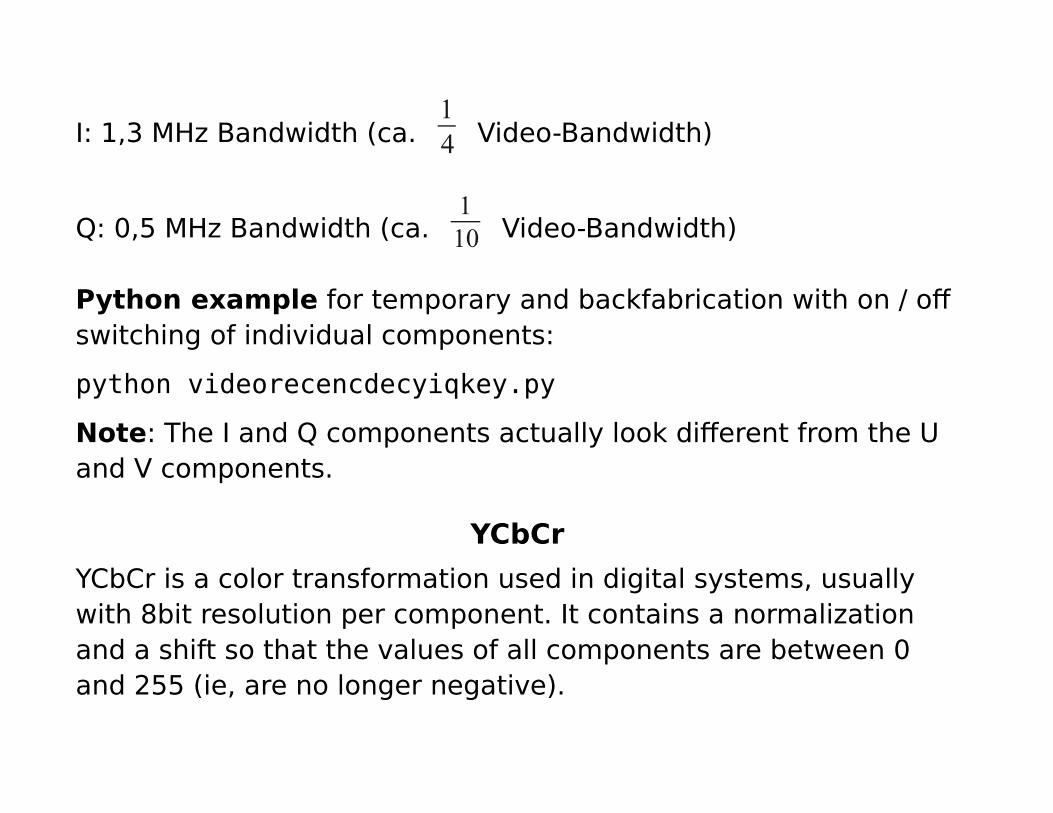
I: 1,3 MHz Bandwidth (ca. 14 Video-Bandwidth)
Q: 0,5 MHz Bandwidth (ca. 110 Video-Bandwidth)
Python example for temporary and backfabrication with on / offswitching of individual components:
python videorecencdecyiqkey.py
Note: The I and Q components actually look different from the U and V components.
YCbCr
YCbCr is a color transformation used in digital systems, usually with 8bit resolution per component. It contains a normalization and a shift so that the values of all components are between 0 and 255 (ie, are no longer negative).

The color transformation results from YUV :
[Y 'CbCr ]=[
0128128]+[
0.299 0.587 0.114−0.168736 −0.331264 0.5
0.5 −0.418688 −0.081312]⋅|R'G 'B'|
Y ', R', G ', B' have the " ‘ " because they now have only values between 0 and 255.
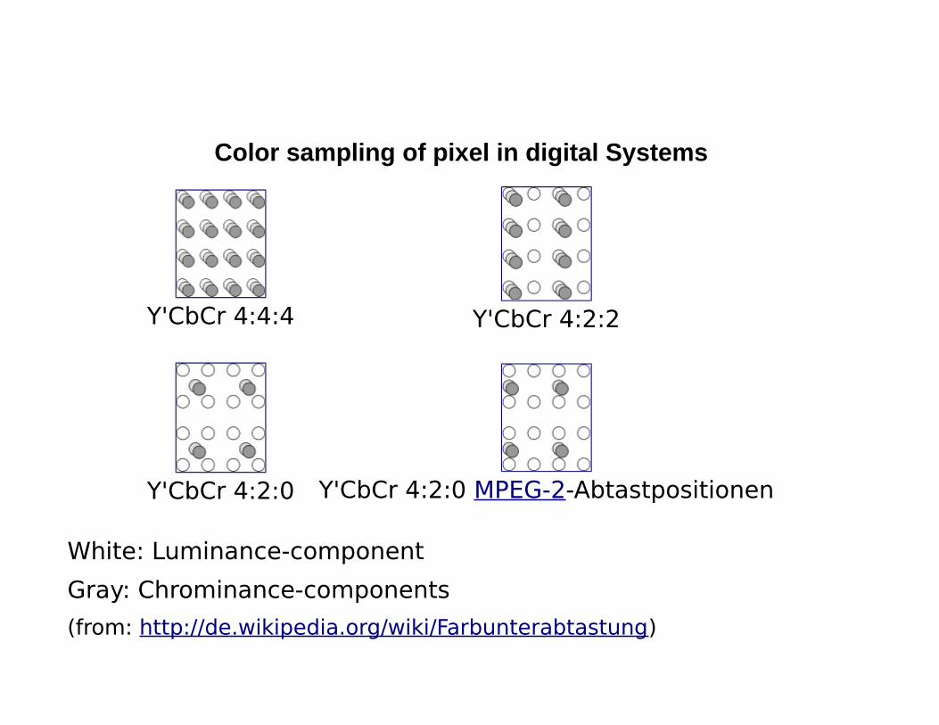
Color sampling of pixel in digital Systems
Y'CbCr 4:4:4 Y'CbCr 4:2:2
Y'CbCr 4:2:0 Y'CbCr 4:2:0 MPEG-2-Abtastpositionen
White: Luminance-component
Gray: Chrominance-components
(from: http://de.wikipedia.org/wiki/Farbunterabtastung)
Note: At 4: 2: 0, the color components are transferred only every second pixel horizontally and vertically.
In this way, a color component requires ¼ the number of pixels asthe Y component. The two color components together therefore only need ½ of the pixel number of the Y component.
A color image can thus be transmitted with a 1.5-fold bit rate as the pure Y component. Compared to the original RGB representation, which requires 3 times as many bits as the Y component, this is a saving by the factor of 2, without visible quality loss!
Color mixing
The color of a pixel is determined from ratio of intensities of its primary colors.
Python example:
python imagecolordisp.py
With keyboard control of intensities of the primary color:
colormix.py
Note: If we multiply all 3 color components R, G, B by the same factor, only the brightness changes but not the color!
So if we are only interested in the color, we can choose an arbitrary definition for the brightness, for example:
R+G+B=constant
Question: If we want to have a certain color, how do we get the corresponding relationship of the basic colors to each other? e.g. On websites, in HTML, colors are given as 6-digit hexadecimal number (since each basic color is represented with 8 bits and 1 hexadecimal is 4 bits), eg:
"#AAFFCC", in RGB format.
Or: If we know the basic colors of a monitor or camera, how do we determine its color space?
For this, we construct a color space whose axes are the hypothetical outputs of the red (x) and green (y) cones. These arenormalized to the range of 0 to 1.
This results in the so-called "CIE standard color chart".
x+y+z=1
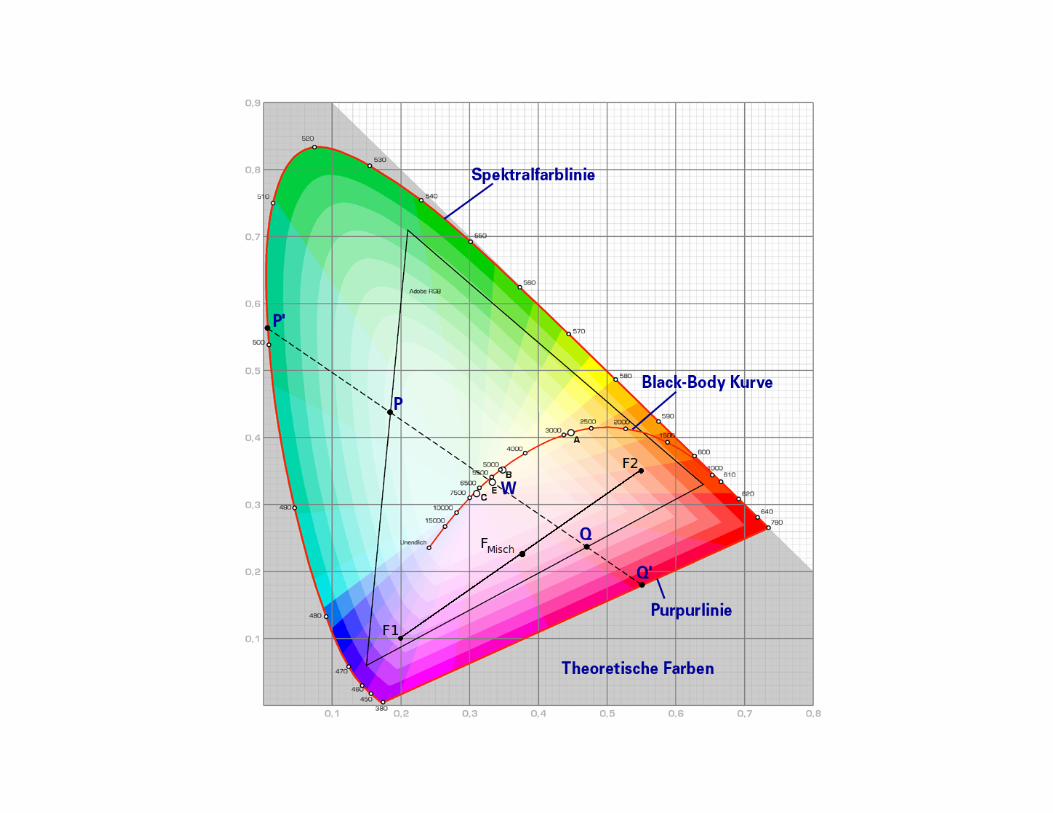
It results in so called „CIE- Standard color space“.
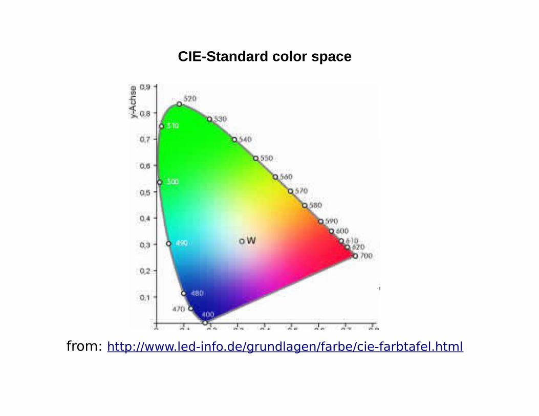
CIE-Standard color space
from: http://www.led-info.de/grundlagen/farbe/cie-farbtafel.html
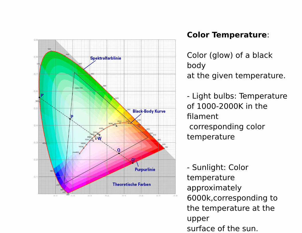
Color Temperature:
Color (glow) of a black bodyat the given temperature.
- Light bulbs: Temperatureof 1000-2000K in the filament corresponding color temperature
- Sunlight: Color temperature approximately 6000k,corresponding to the temperature at the upper surface of the sun.
Color mixing with color space
In order to mix 2 colors in this color space, we multiply their coordinates by factors, which are between 0 and 1 and the result of the sum is 1 :
Color1=(x1,y1)
Color2=(x2,y2)
Mixed color=a*color1+b*color2
with a+b=1, a>=0, b>=0.
The sum a + b must be 1, so that the mixing color again satisfies x + y + z = 1 for its components as normalization for the brightness.
Python example:
imagecolormixdisp.py
colormix.py
Note: The larger the factor of a color, the more the mixed color becomes to it.
Note: On the CIE standard color chart, all mix colors are located on the connection line of the 2 colors.
If we take another color, all possible mixing colors lie within the connected triangle of the three colors to be mixed. In this manner, e.g. The color space of a monitor. The colors to be mixedare the colors of its basic color dyes (phosphors in picture tubes). This is shown in the following diagram.
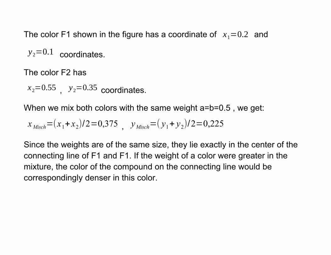
The color F1 shown in the figure has a coordinate of x1=0.2 and
y2=0.1 coordinates.
The color F2 has
x2=0.55 , y2=0.35 coordinates.
When we mix both colors with the same weight a=b=0.5 , we get:
xMisch=(x1+x2)/2=0,375 , yMisch=( y1+ y2)/2=0,225
Since the weights are of the same size, they lie exactly in the center of the connecting line of F1 and F1. If the weight of a color were greater in the mixture, the color of the compound on the connecting line would be correspondingly denser in this color.
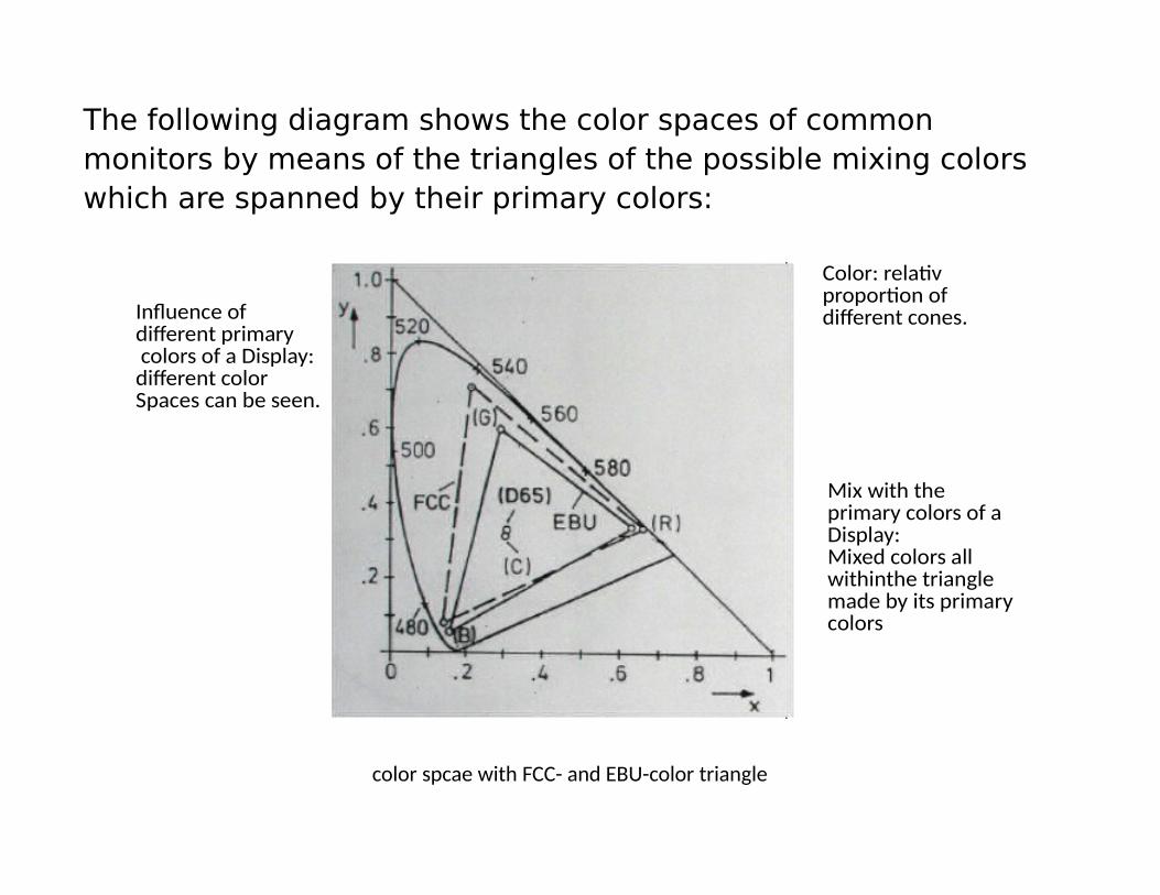
The following diagram shows the color spaces of common monitors by means of the triangles of the possible mixing colors which are spanned by their primary colors:
color spcae with FCC- and EBU-color triangle
Influence of different primary colors of a Display: different color Spaces can be seen.
Color: relativ proportion of different cones.
Mix with the primary colors of a Display: Mixed colors all withinthe triangle made by its primary colors
Color Space Test for Monitors
The following Python Script shows the full color space of a monitor.
Horizontal on the x axis, the value of the red component is increased from 0 to 1 (full control) (1 is right),
Vertically on the y axis the value of the green component is increased from 0 to 1 (1 is above),
The value of the blue component is selected such that the sum
R + G + B = 1
is satisfied,
ie B = 1-R-G.
Therefore only colors appear in the lower triangle, because in the upper triangle the value of the blue component would become negative.
Run with:
python imagecolortriangledisp.py
When comparing with different monitors next to each other, we will notice differences.
At this triangle, we can now also see what conditions our color components have for a desired color: We select the point of the desired color in this color triangle, and then read off the valueof the red component on the x axis at which Y is the value for green, and the difference of the sum of the two to 1 is the blue value.
Attention:
Above is the full green, the blueest blue below, and the redest red on the right.
This triangle corresponds to the triangles for different monitors in the above CIE color chart. One can see: there is still reserve in the green area.