lecture i: graphics & image data representation data types the most common data types for...
TRANSCRIPT
LECTURE I:
GRAPHICS & IMAGE DATA
REPRESENTATION
DR. OUIEM BCHIR
1
DIGITAL IMAGE
REPRESENTATION
An image is a spatial representation of an object, a2D or 3D
scene, etc.
Abstractly, an image is a continuous function
defining a rectangular region of a plane
An image can be thought of as a function with resulting values
of the light intensity at each point over a planar region.
2
DIGITAL IMAGE
REPRESENTATION
For computer representation, the function (e.g. intensity) must
be sampled at discrete intervals.
Sampling quantizes the intensity values into discrete intervals.
Points at which an image is sampled are called picture
elements or pixels.
Resolution: specifies the distance between points - accuracy
3
DIGITAL IMAGE
REPRESENTATION
A digital image is represented by a matrix of numeric values
each representing a quantized intensity value.
I(r,c) - intensity value at position corresponding to row r and
column c of the matrix.
Intensity value can be represented by
1-bit: black & white images
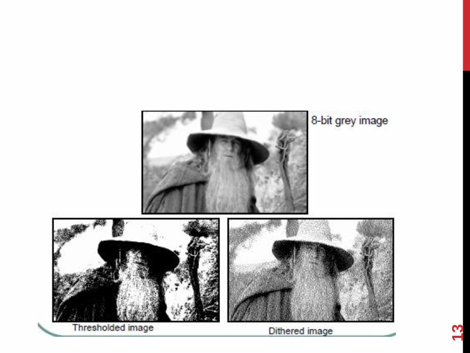
8-bits: grayscale images
24-bits: color images (RGB)
4
1-BIT IMAGES
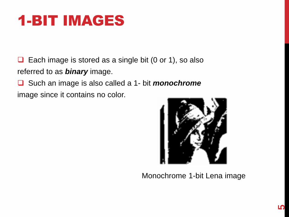
Each image is stored as a single bit (0 or 1), so also
referred to as binary image.
Such an image is also called a 1- bit monochrome
image since it contains no color.
Monochrome 1-bit Lena image
5
8-BIT GRAY-LEVEL
IMAGES
Each pixel has a gray- value between 0 and 255. Each pixel is
represented by a single byte: e.g. dark pixels might have a
value of 10, and a bright one might be 230.
Bitmap: The two- dimensional array of pixel values that
represent the graphics/image data.
Image resolution: The number of pixels in a digital image
(higher resolution better quality).
6
8-BIT GRAY-LEVEL
IMAGE
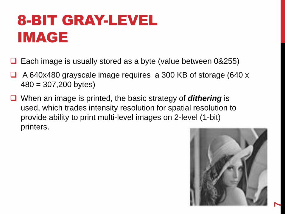
Each image is usually stored as a byte (value between 0&255)
A 640x480 grayscale image requires a 300 KB of storage (640 x
480 = 307,200 bytes)
When an image is printed, the basic strategy of dithering is
used, which trades intensity resolution for spatial resolution to
provide ability to print multi-level images on 2-level (1-bit)
printers.
7
DITHERING
Dithering is used to calculate patterns of dots such that values
from 0 to 255 correspond to patterns that are more and more
filled at darker pixel values, for printing on a 1-bit printer.
Main strategy: replace a pixel value by a larger pattern, say
2x2 or 4x4, such that the number of printed dots approximates
the varying-sized disks of ink used in analog, in halftone
printing (e.g. for newspaper photos).
Half-tone printing is an analog process that uses smaller or
larger filled circles of black ink to represent shading, for
newspaper printing.
8
DITHERING
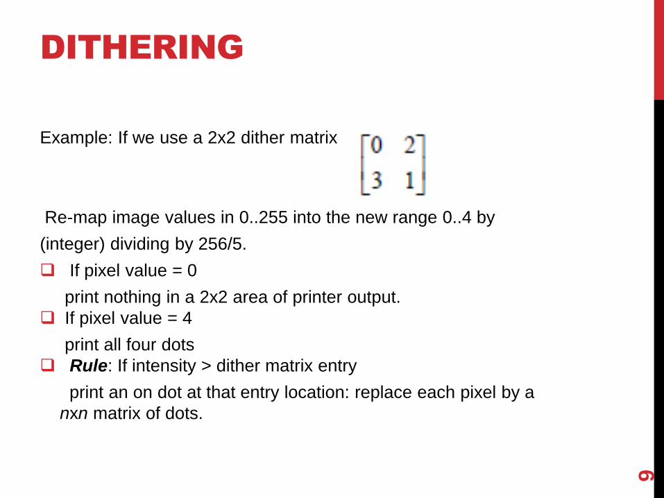
Example: If we use a 2x2 dither matrix
Re-map image values in 0..255 into the new range 0..4 by
(integer) dividing by 256/5.
If pixel value = 0
print nothing in a 2x2 area of printer output.
If pixel value = 4
print all four dots
Rule: If intensity > dither matrix entry
print an on dot at that entry location: replace each pixel by a
nxn matrix of dots.
9
DITHERING
Note: Image size may be much larger for a dithered image
(replacing each pixel by a 2x2 array of dots, makes an image 4
times as large).
Can get around this problem.
Ordered dither: turn on the printer output bit for a pixel if the
intensity level is greater than the particular matrix element just
at that pixel position
10
AN ALGORITHM FOR
ORDERED DITHER
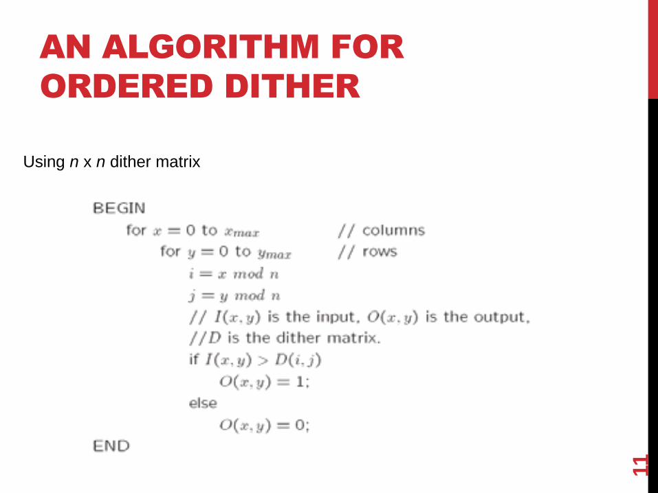
Using n x n dither matrix
11
EXAMPLE
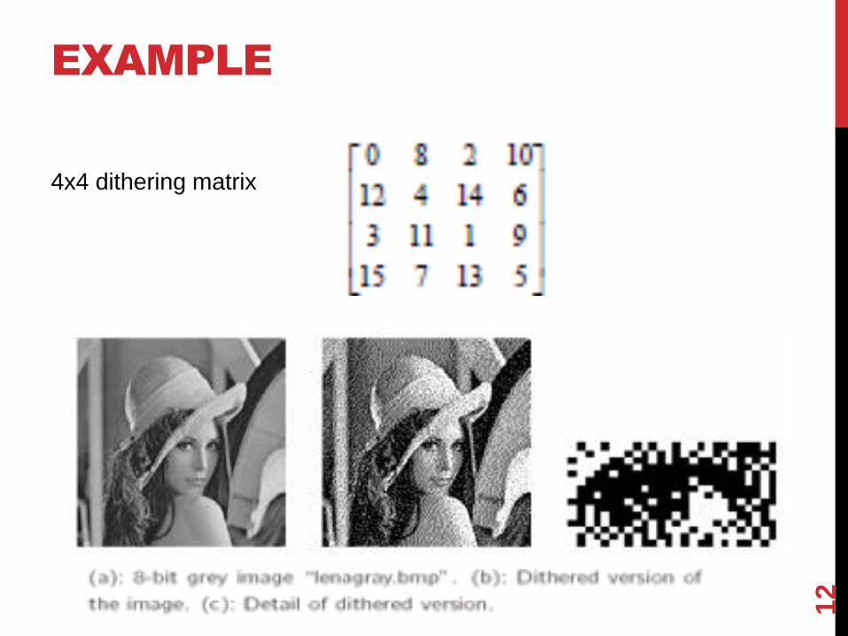
4x4 dithering matrix
12
13

IMAGE DATA TYPES
The most common data types for graphics and image file
formats: 24-bit color and 8-bit color.
Some formats are restricted to particular hardware/operating
system platforms, while others are “cross-platform” formats.
Even if some formats are not cross-platform, there are
conversion applications that will recognize and translate
formats from one system to another.
Most image formats incorporate some variation of
compression technique due to the large storage size of image
files. Compression techniques can be classified into either
lossless or lossy.
14
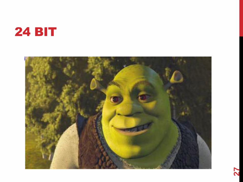
24-BIT COLOR IMAGES
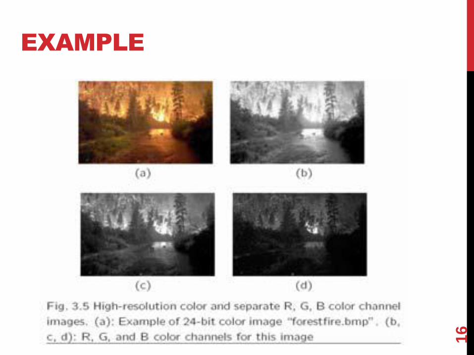
In a color 24- bit image, each pixel is represented by three
bytes, usually representing R, G, B.
This format supports 256 x 256 x 256 possible combined
colors, or a total of 16,777,216 possible colors.
Such flexibility does result in a storage penalty:
A 640 x 480 24-bit color image would require 921.6 KB of
storage without any compression.
15
EXAMPLE
16
8-BIT COLOR IMAGES
Many systems can make use of 8 bits of color information (the
so-called “256 colors”) in producing a screen image.
Such image files use the concept of a lookup table to store
color information.
Basically, the image stores not color, but instead just a set of
bytes, each of which is actually an index into a table with 3-
byte values that specify the color for a pixel with that lookup
table index.
17
COLOR QUANTIZATION
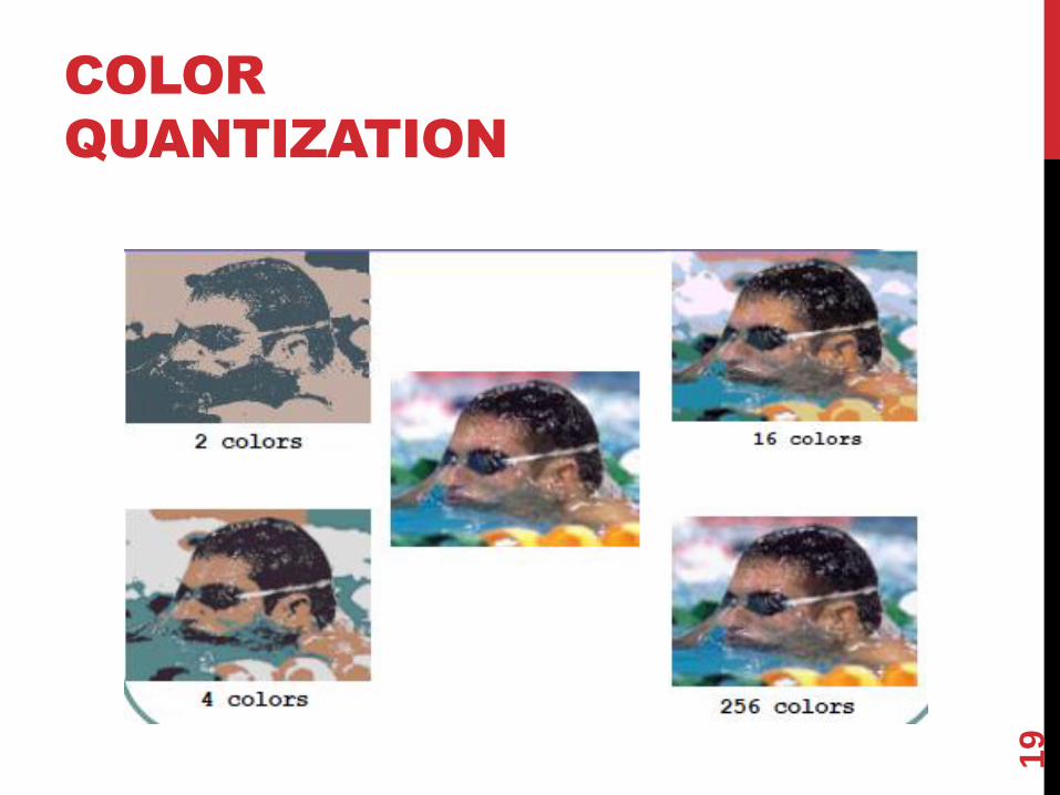
With 8 bits per pixel and color lookup table we can display at
most 256 distinct colors at a time.
To do that we need to choose an appropriate set of
representative colors and map the image into these colors
18
COLOR
QUANTIZATION
19
QUANTIZATION PHASES
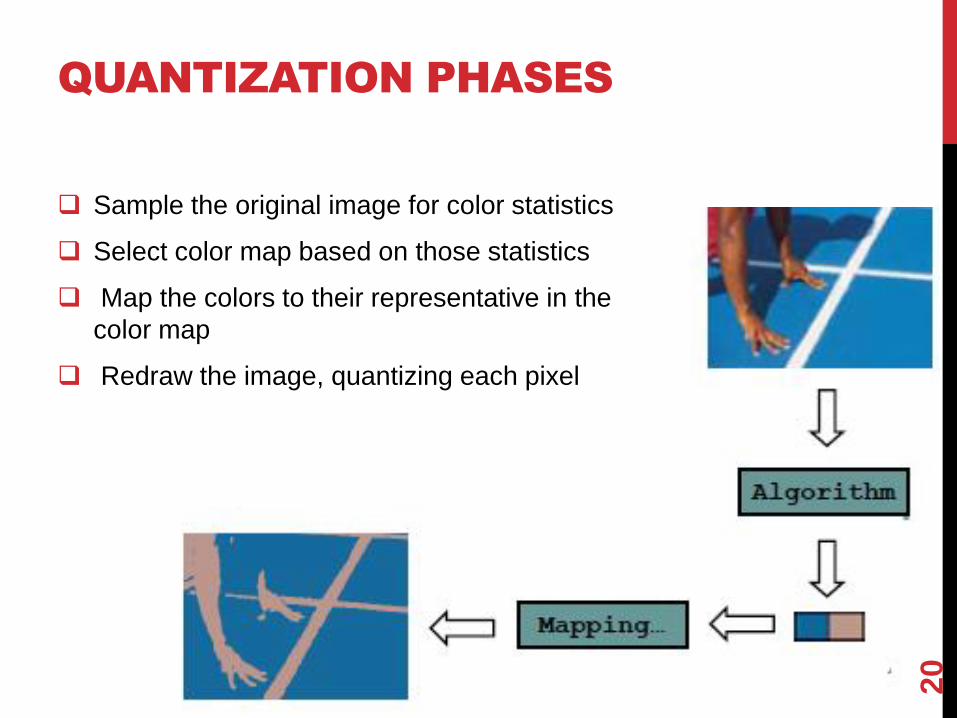
Sample the original image for color statistics
Select color map based on those statistics
Map the colors to their representative in the
color map
Redraw the image, quantizing each pixel
20
COLOR LOOK-UP TABLES
(LUTS)
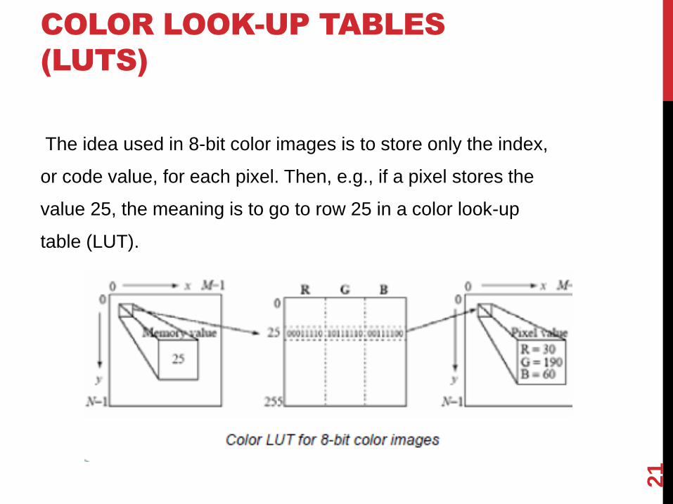
The idea used in 8-bit color images is to store only the index,
or code value, for each pixel. Then, e.g., if a pixel stores the
value 25, the meaning is to go to row 25 in a color look-up
table (LUT).
21
HOW TO DEVISE A
COLOR LUT?
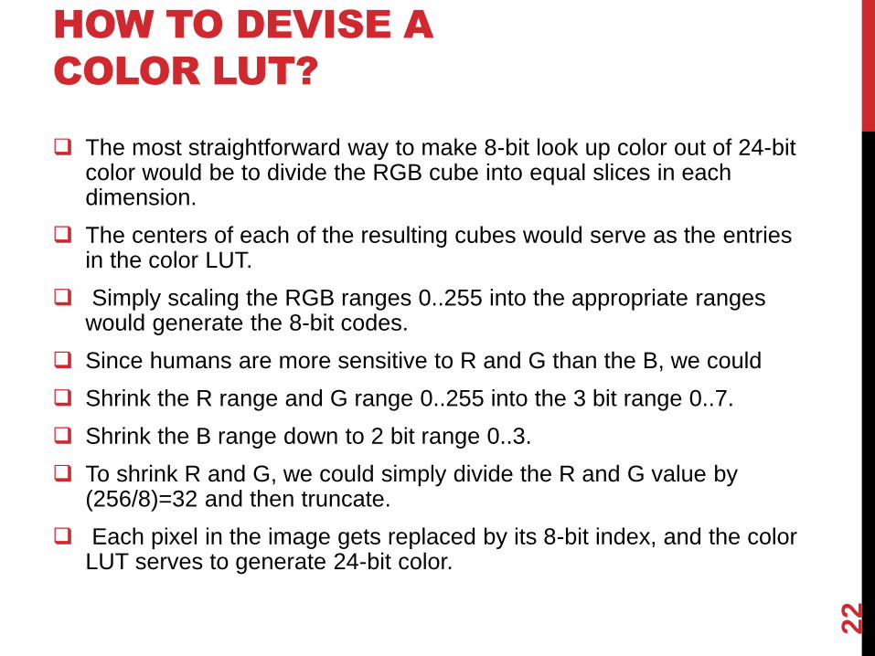
The most straightforward way to make 8-bit look up color out of 24-bit
color would be to divide the RGB cube into equal slices in each dimension.
The centers of each of the resulting cubes would serve as the entries in the color LUT.
Simply scaling the RGB ranges 0..255 into the appropriate ranges would generate the 8-bit codes.
Since humans are more sensitive to R and G than the B, we could
Shrink the R range and G range 0..255 into the 3 bit range 0..7.
Shrink the B range down to 2 bit range 0..3.
To shrink R and G, we could simply divide the R and G value by (256/8)=32 and then truncate.
Each pixel in the image gets replaced by its 8-bit index, and the color LUT serves to generate 24-bit color.
22
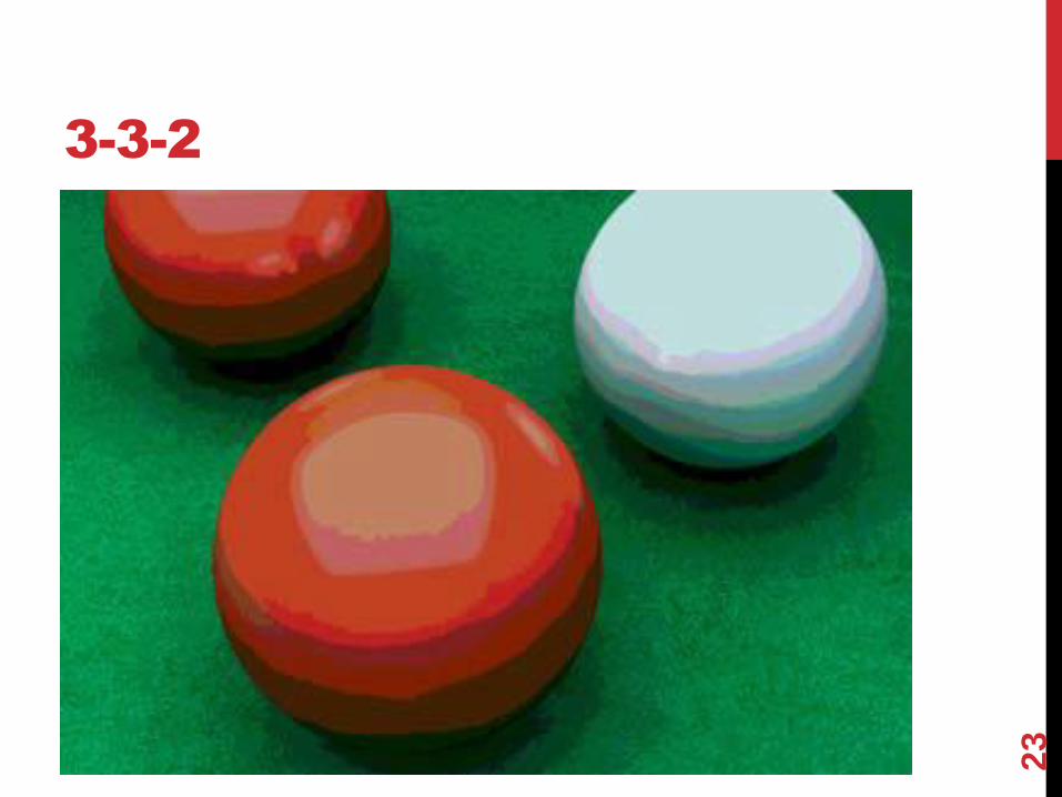
3-3-2
23
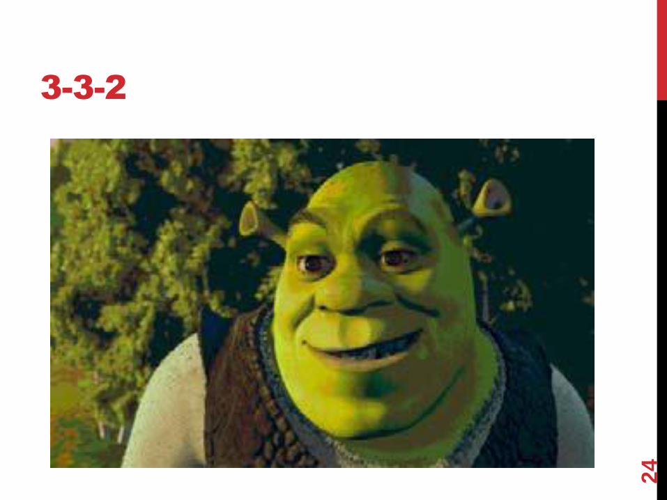
3-3-2
24
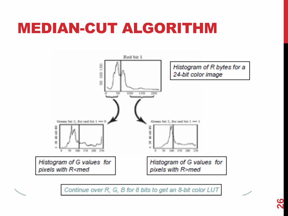
MEDIAN-CUT ALGORITHM
A simple alternative solution that does a better job for the color
reduction problem.
Sort the R byte values and find their median.
Values smaller than the median are labeled with a “0” bit.
Values larger than the median are labeled with a “1” bit.
This type of scheme will concentrate bits where they most need to
differentiate between high populations of close
colors.
We can easily visualize finding the median by using a histogram
showing counts at position 0..255.
25
MEDIAN-CUT ALGORITHM
26
24 BIT
27