lecture no. 4 - kasetsart · pdf file203552 advanced soil mechanics dr.warakorn mairaing 1 1...
TRANSCRIPT
203552 Advanced Soil Mechanics
Dr.Warakorn Mairaing 1
1
Dr. Warakorn MairaingAssociate Professor
Civil Engineering DepartmentKasetsart University, Bangkok Tel: 02-579-2265Email: [email protected]
Dr. Warakorn MairaingDr. Warakorn MairaingAssociate ProfessorAssociate Professor
Civil Engineering DepartmentCivil Engineering DepartmentKasetsart University, Bangkok Kasetsart University, Bangkok Tel: 02Tel: 02--579579--22652265Email: [email protected]: [email protected]
Lecture No. 4
Two extreme conditions are normally considered for design and analysis.
DRAINED AND UNDRAINED STRENGTHDRAINED AND UNDRAINED STRENGTH
Soil Strength depend highly on pore pressure during loading
1. Drained Strength ; when excess pore pressure (Δu) ≅ 0
during loading or after fully dissipation of Δu 2 typical eases are;
1) Sand or gravel layers of high k Δu dissipate fast
2) Clayey soil with slow rate of loading small increase of Δu and
longer time of dissipation

203552 Advanced Soil Mechanics
Dr.Warakorn Mairaing 2
Ex.
1) Saturated clay with high rate of loading
2) Silt and fine sand with seismic or repeated load Accumulation
of pore pressure Boiling
2. Undrained Strength ; when Δu remained during loading
Δu fully developed and remained “Fully undrained condition”
Δu partially is dissipated “Partialy drained”
Mohr – Coulomb’s Effective Strength Equation
( ) φστ tan⋅Δ−−+= uuc s
us = Constant
Δu = varied during loading
Drained or Effective strength concept
usually applied for Δu = 0 or known Δu
Undrainred or Total strength concept
for Δu is fully deveoped or unknow Δu (high)
“Stress-path method” is normally used to explain drained and
Undrained soil strength.
203552 Advanced Soil Mechanics
Dr.Warakorn Mairaing 3
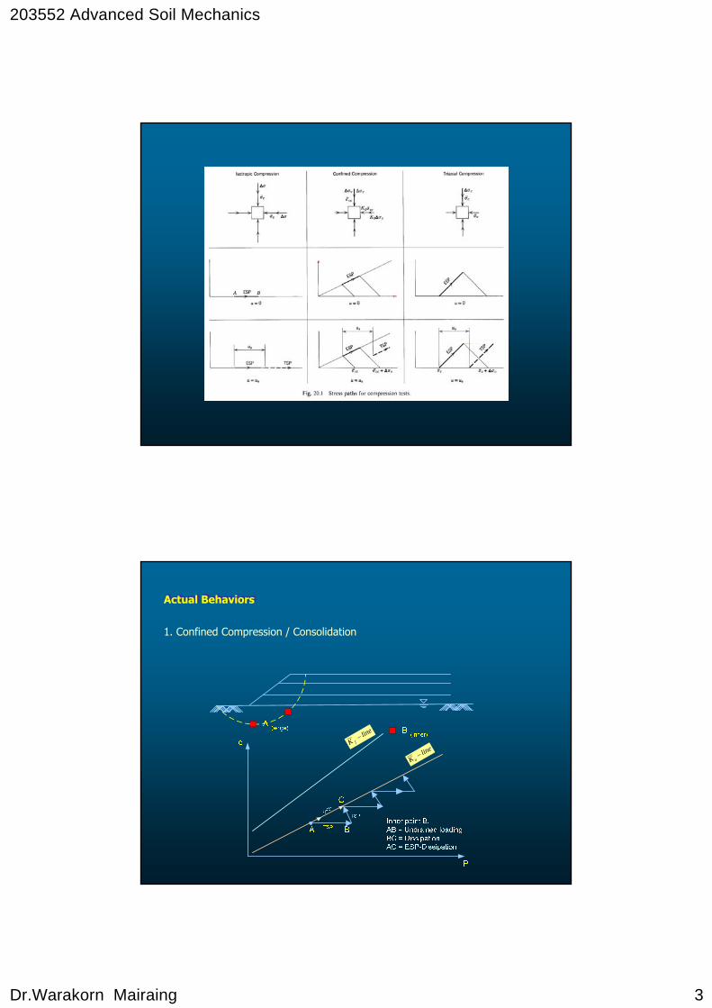
1. Confined Compression / Consolidation
lineK f
−
lineK o
−
Actual BehaviorsActual Behaviors
203552 Advanced Soil Mechanics
Dr.Warakorn Mairaing 4
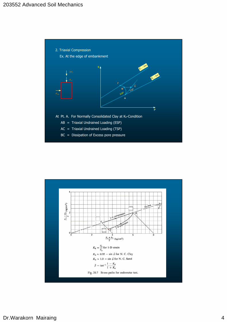
2. Triaxial Compression
Ex. At the edge of embankment
At Pt. A. For Normally Consolidated Clay at Ko-Condition
AB = Triaxial Undrained Loading (ESP)
AC = Triaxial Undrained Loading (TSP)
BC = Dissipation of Excess pore pressure
lineK f
−
lineK o
−
ESPTSP
vσΔ
voσ
HOσ
203552 Advanced Soil Mechanics
Dr.Warakorn Mairaing 5
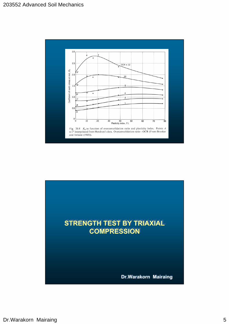
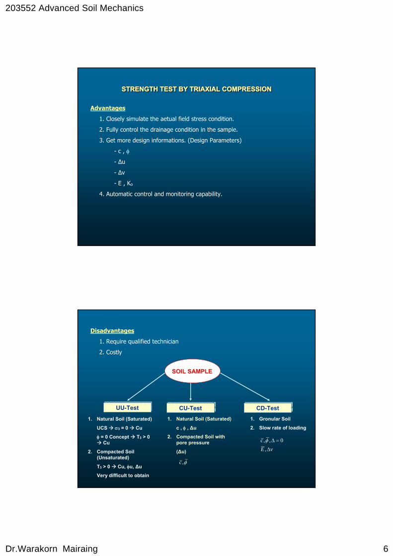
STRENGTH TEST BY TRIAXIAL COMPRESSION
STRENGTH TEST BY TRIAXIAL COMPRESSION
Dr.Warakorn MairaingDr.Warakorn Mairaing
203552 Advanced Soil Mechanics
Dr.Warakorn Mairaing 6
Advantages
1. Closely simulate the aetual field stress condition.
2. Fully control the drainage condition in the sample.
3. Get more design informations. (Design Parameters)
- c , φ
- Δu
- Δv
- E , Ko
4. Automatic control and monitoring capability.
STRENGTH TEST BY TRIAXIAL COMPRESSIONSTRENGTH TEST BY TRIAXIAL COMPRESSIONSTRENGTH TEST BY TRIAXIAL COMPRESSION
Disadvantages
1. Require qualified technician
2. Costly
SOIL SAMPLE
UU-TestUU-Test CU-TestCU-Test CD-TestCD-Test
1. Natural Soil (Saturated)
UCS σ3 = 0 Cu
φ = 0 Concept T3 > 0 Cu
2. Compacted Soil (Unsaturated)
T3 > 0 Cu, φu, Δu
Very difficult to obtain
1. Natural Soil (Saturated)
c , φ , Δu
2. Compacted Soil with pore pressure
(Δu)
1. Gronular Soil
2. Slow rate of loading
φ,c
vEc
Δ
=Δ
,0,,φ
203552 Advanced Soil Mechanics
Dr.Warakorn Mairaing 7
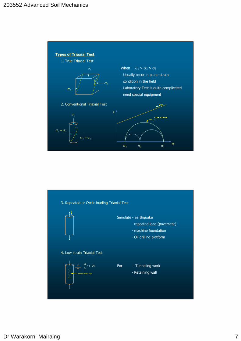
Types of Triaxial Test
1. True Triaxial Test
When σ1 > σ2 > σ3
- Usually occur in plane-strain
condition in the field
- Laboratory Test is quite complicated
need special equipment
2. Conventional Triaxial Test
1σ
2σ
3σ
3σσ =c
1σ
3σσ =c
3σ 2σ 1σ σ
τ
3. Repeated or Cyclic loading Triaxial Test
Simulate - earthquake
- repeated load (pavement)
- machine foundation
- Oil drilling platform
4. Low strain Triaxial Test
For - Tunneling work
- Retaining wallSpecial Strain Gage
%21−≈Δ
oLL
203552 Advanced Soil Mechanics
Dr.Warakorn Mairaing 8
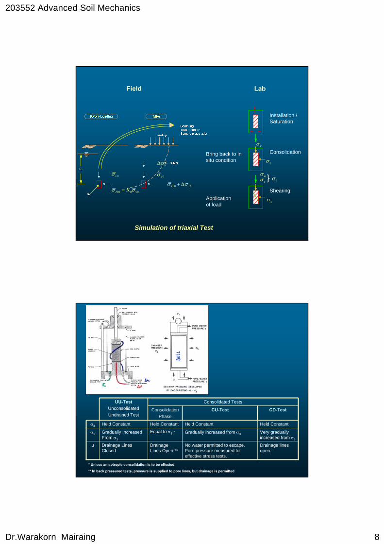
Field Lab
0vσ
000 vH K σσ =
vσΔ
0vσ
HH σσ Δ+0
Simulation of triaxial Test
Installation /Saturation
Consolidation
ShearingApplication of load
Bring back to in situ condition
cσ
cσ
aσcσ 1σ
cσ
CD-TestCU-TestConsolidationPhase
Drainage lines open.
No water permitted to escape. Pore pressure measured for effective stress tests.
Drainage Lines Open **
Drainage Lines Closed
u
Very gradually increased from σ3
Gradually increased from σ3Equal to σ3 *Gradually Increased From σ3
σ1
Held ConstantHeld ConstantHeld ConstantHeld Constantσ3
Consolidated TestsUU-TestUnconsolidatedUndrained Test
* Unless anisotropic consolidation is to be effected
** In back pressured tests, pressure is supplied to pore lines, but drainage is permitted

203552 Advanced Soil Mechanics
Dr.Warakorn Mairaing 9
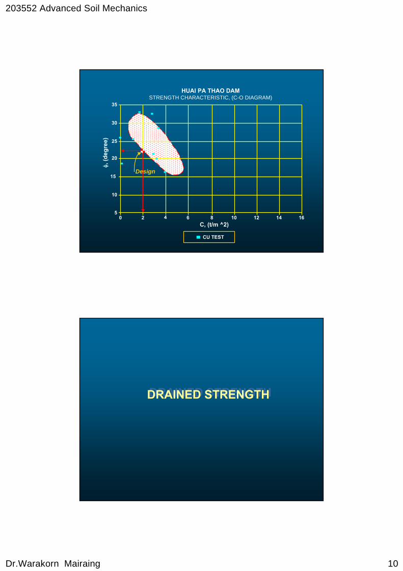
0 2 4 6 8 10 12 14 165
15
20
25
30
35
10
C, (t/m ^2)
, (de
gree
)
HUAI PA THAO DAMSTRENGTH CHARACTERISTIC, (C-O DIAGRAM)
UU TEST
Design
203552 Advanced Soil Mechanics
Dr.Warakorn Mairaing 10
0 2 4 6 8 10 12 14 165
15
20
25
30
35
10
C, (t/m ^2)
, (de
gree
)
HUAI PA THAO DAMSTRENGTH CHARACTERISTIC, (C-O DIAGRAM)
CU TEST
Design
DRAINED STRENGTHDRAINED STRENGTH
203552 Advanced Soil Mechanics
Dr.Warakorn Mairaing 11
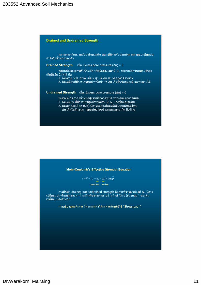
สภาพการเกิดความดันน้ําในมวลดิน ขณะที่มีการรับน้ําหนักจากภายนอกมีผลตอกําลังรับน้ําหนักของดิน
Drained Strength เมื่อ Excess pore pressure (Δu) ≅ 0
ตลอดชวงระยะการรับน้ําหนัก หรือในชวงเวลาที่ Δu ระบายออกจนหมดแลวจะเกิดขึ้นใน 2 กรณี คือ
1. ดินทราย หรือ กรวด เมื่อ k สูง Δu ระบายออกไดรวดเร็ว2. ดินเหนียวทีมกีารบรรทุกน้ําหนักชา Δu เกิดขึ้นนอยและมีเวลาระบายได
Undrained Strength เมื่อ Excess pore pressure (Δu) ≠ 0
ในชวงท่ีเกิดกําลังน้ําหนักสูงจนมีโอกาสพิบัติ หรือเส่ียงตอการพิบัติ1. ดินเหนียว ท่ีมกีารบรรทุกน้ําหนักเร็ว Δu เกิดขึ้นและสะสม2. ดินทรายละเอียด (Silt) มีการสั่นสะเทือนหรือมีแรงแผนดินไหวΔu เกิดในลักษณะ repeated load และสะสมจนเกิด Boiling
Drained and Undrained Strength
Mohr-Coulomb’s Effective Strength Equation
( ) φστ tan⋅Δ−−+= uuc s
Constant Varied
การศึกษา drained และ undrained strength คือการพิจารณาชวงท่ี Δu มีการเปล่ียนแปลงในขณะบรรทุกน้ําหนักหรือขณะระบายน้ําแลวทําให τ (strength) ของดินเปล่ียนแปลงไปดวย
การอธิบายพฤติกรรมนี้สามารถทําไดสะดวกโดยใชวิธี “Stress path”
203552 Advanced Soil Mechanics
Dr.Warakorn Mairaing 12
1
2
3
4
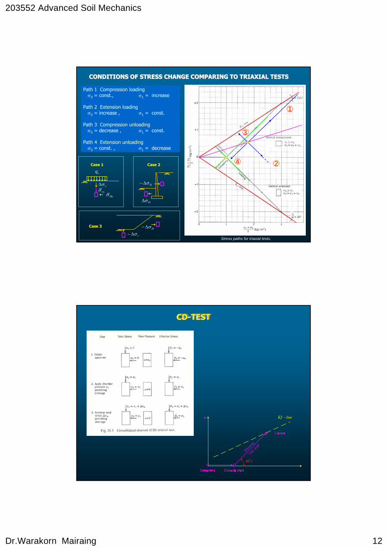
Stress paths for triaxial tests.
CONDITIONS OF STRESS CHANGE COMPARING TO TRIAXIAL TESTSCONDITIONS OF STRESS CHANGE COMPARING TO TRIAXIAL TESTS
Path 1 Compression loadingσ3 = const., σ1 = increase
Path 2 Extension loadingσ3 = increase , σ1 = const.
Path 3 Compression unloadingσ3 = decrease , σ1 = const.
Path 4 Extension unloadingσ3 = const. , σ1 = decrease
Case 1 Case 2
Case 3
sq
vσΔvoσ
Hoσ
HσΔ−
HσΔ
HσΔ−
vσΔ−
CD-TESTCD-TEST
TSP, ESP
Sheari
ng
linefK −

203552 Advanced Soil Mechanics
Dr.Warakorn Mairaing 13
CU-TESTCU-TEST
q
P
ESP
TSP
u
UU TestUU Test
q
TSP
ur+Bσc
P
ESP
u
DΔσa

203552 Advanced Soil Mechanics
Dr.Warakorn Mairaing 14
InitialConsolidation?
CellPressure?
IsotropicConsokidation?
UnconfinedCompression
UDrained
Shearing?Drained
Shearing?
NoCAU
YesCAD
Shearing in Shearing in
Extension Compression
CAUE CAUC
Extension Compression
CADE CADC
NoCIU
YesCID
Shearing in Shearing in
Extension Compression
CIUE CIUC
Extension Compression
CIDE CIDC
UU
YesNo
YesNo NoCA
YesCI
1
2 31 UU – Unconsolidated Undrained
2 CU – Consolidated Undrained with pore pressure measurement
3 CD – Consolidated Drained.
1 UU – Unconsolidated Undrained
2 CU – Consolidated Undrained with pore pressure measurement
3 CD – Consolidated Drained.
Triaxial Tests.Triaxial Tests.
DRAINED SHEAR STRENGTHDRAINED SHEAR STRENGTH
203552 Advanced Soil Mechanics
Dr.Warakorn Mairaing 15
I. FIELD CONDITION
- Granular materials , dry or partially saturated.- Cohesive materials , slow rate of loading
DRAINED SHEAR STRENGTHDRAINED SHEAR STRENGTH
II. LABORATORY CONDITION
- Slow rate of loading, drainage permitted, excess pore pressure (Δu) = 0
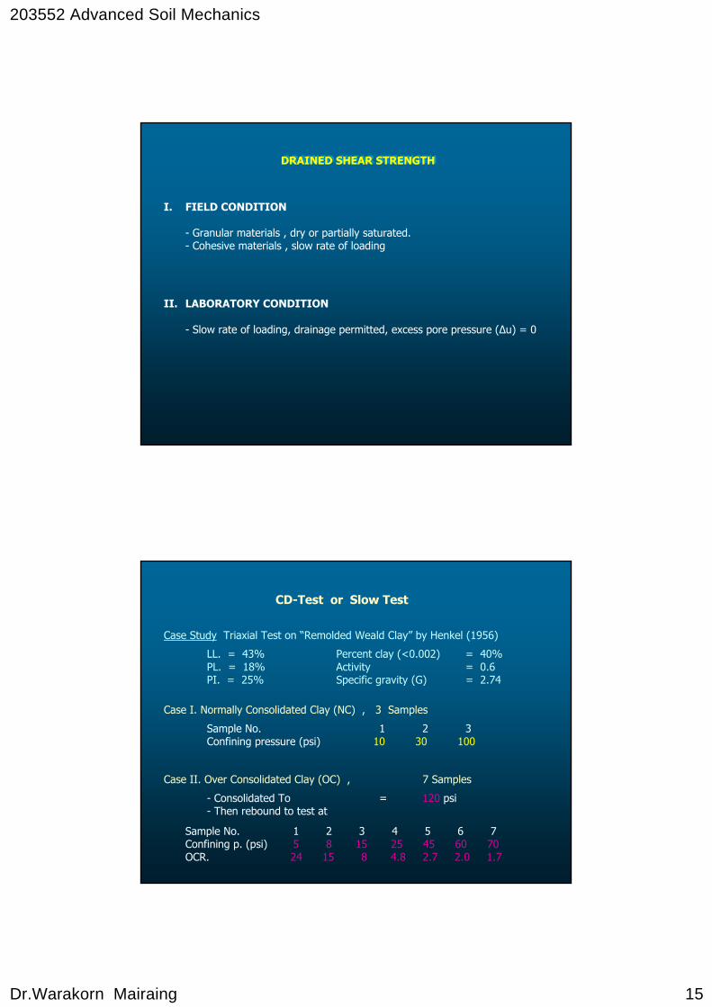
Case II. Over Consolidated Clay (OC) , 7 Samples
- Consolidated To = 120 psi- Then rebound to test at
Sample No. 1 2 3 4 5 6 7Confining p. (psi) 5 8 15 25 45 60 70OCR. 24 15 8 4.8 2.7 2.0 1.7
CD-Test or Slow Test
Case Study Triaxial Test on “Remolded Weald Clay” by Henkel (1956)
LL. = 43% Percent clay (<0.002) = 40%PL. = 18% Activity = 0.6PI. = 25% Specific gravity (G) = 2.74
Case I. Normally Consolidated Clay (NC) , 3 Samples
Sample No. 1 2 3Confining pressure (psi) 10 30 100
203552 Advanced Soil Mechanics
Dr.Warakorn Mairaing 16
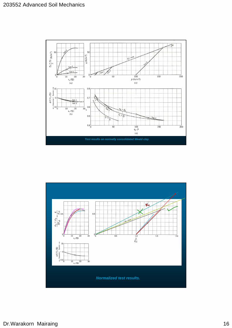
Test results on normally consolidated Weald clay.
Normalized test results.
Kf
203552 Advanced Soil Mechanics
Dr.Warakorn Mairaing 17
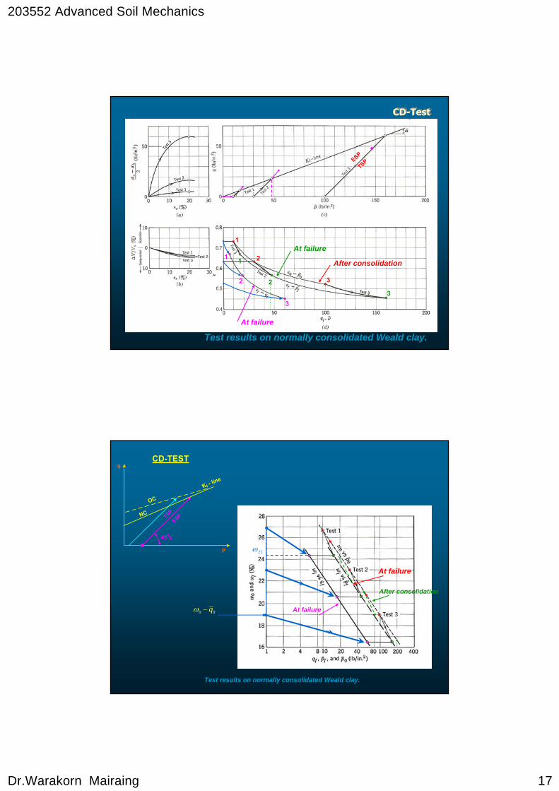
CD-TestCD-Test
1
2
3
32
11
2
3
At failure
After consolidation
At failure
ESP
TSP
Test results on normally consolidated Weald clay.
q
ESPTSP
450c
P
NC
OC
Kf - line
CD-TEST
Test results on normally consolidated Weald clay.
At failure
After consolidation
At failure00 q−ω
1fω
203552 Advanced Soil Mechanics
Dr.Warakorn Mairaing 18
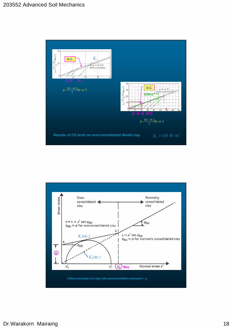
Results of CD tests on overconsolidated Weald clay. 2./120 inlbpm =
1
( ) ( )231 ./2
inlbp σσ +=
2 3
3 4 5
( ) ( )231 ./2
inlbp σσ +=
6 7
fKO.C.
OCR>2
O.C.
Failure envelope of a clay with preconsolidation pressure = σc´
Max
( ).Kf NC
( ).Kf OC
203552 Advanced Soil Mechanics
Dr.Warakorn Mairaing 19
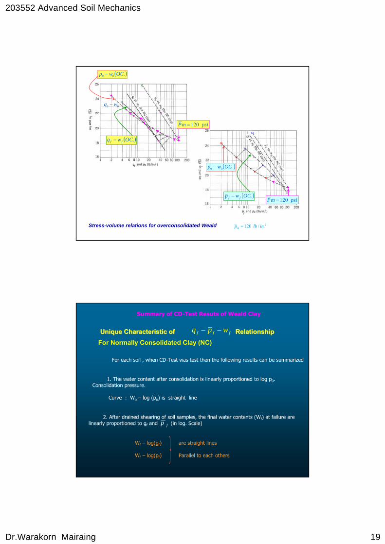
Stress-volume relations for overconsolidated Weald 2./120 inlbpm =
psimP 120=
( ).OCwq ff −
( ).00 OCwp −
00 wq −
psimP 120=( ).OCwp ff −
( ).00 OCwp −
2. After drained shearing of soil samples, the final water contents (Wf) at failure are linearly proportioned to gf and (in log. Scale)
fff wpq −−
fp
Unique Characteristic of RelatiUnique Characteristic of RelationshiponshipFor Normally Consolidated Clay (NC)
For each soil , when CD-Test was test then the following results can be summarized
1. The water content after consolidation is linearly proportioned to log p0. Consolidation pressure.
Curve : Wo – log (po) is straight line
Wf – log(gf) are straight lines
Wf – log(pf) Parallel to each others
Summary of CD-Test Resuts of Weald Clay

203552 Advanced Soil Mechanics
Dr.Warakorn Mairaing 20
3. After preconsolidation pressures, the samples were rebound to a curtain confining pressure. The wo - will show the lower value than wo of N.C. due to OC. Clay has inelastic property of soil.
4. The unique but not linear relationships between
( ) ( )ffffoo plogw),log(qw,plogw −−−
mP
For Overconsolidated Clay (O.C)
were obtained for each soil at each
Stress-volume relations for overconsolidated Weald 2./120 inlbpm =
psimP 120=
psimP 120=
ff wp −
( ).00 OCwp −
123
().
OCw
q
f
f −
().
0
0
OCw
P−
4
5
6
203552 Advanced Soil Mechanics
Dr.Warakorn Mairaing 21
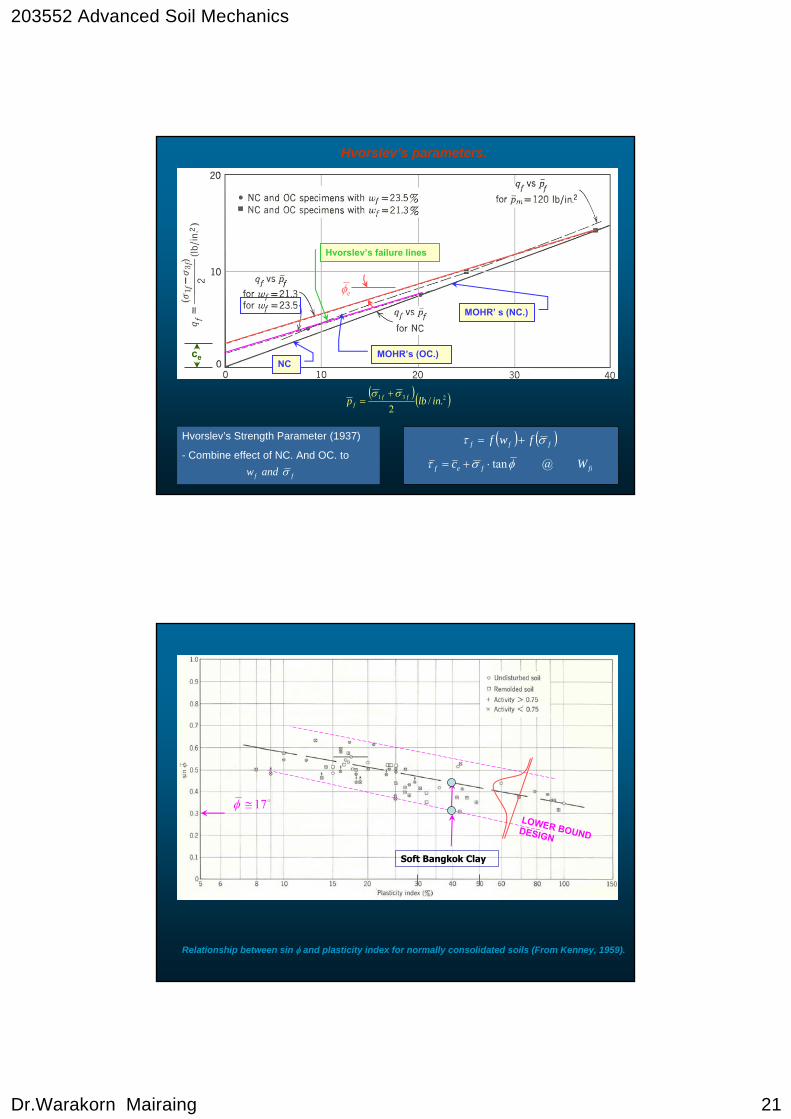
Hvorslev’s parameters.
Hvorslev’s Strength Parameter (1937)
- Combine effect of NC. And OC. to
ff andw σ
( ) ( )fff fwf στ +=
fifef Wc @tanφστ ⋅+=
( )( )231 ./2
inlbp fff
σσ +=
MOHR’ s (NC.)
MOHR’s (OC.)NC
Hvorslev’s failure lines
eφ
ce
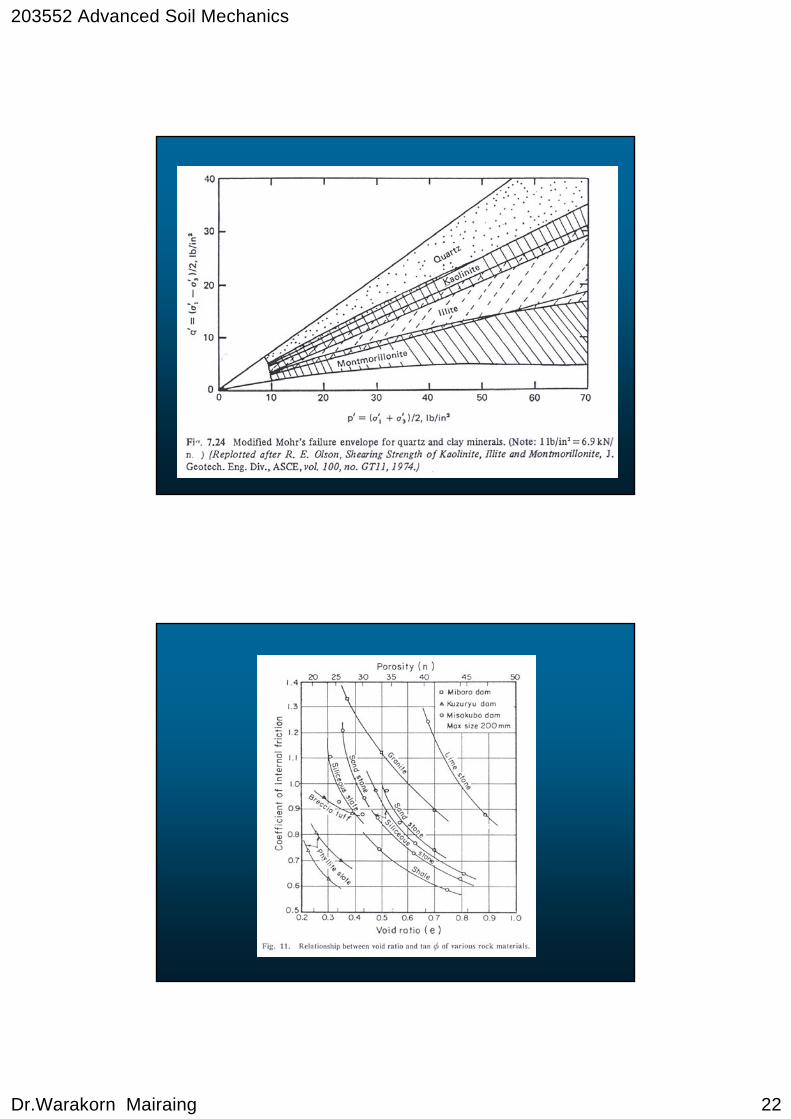
Relationship between sin φ and plasticity index for normally consolidated soils (From Kenney, 1959).
o17≅φLOWER BOUND DESIGN
Soft Bangkok Clay
203552 Advanced Soil Mechanics
Dr.Warakorn Mairaing 22
203552 Advanced Soil Mechanics
Dr.Warakorn Mairaing 23
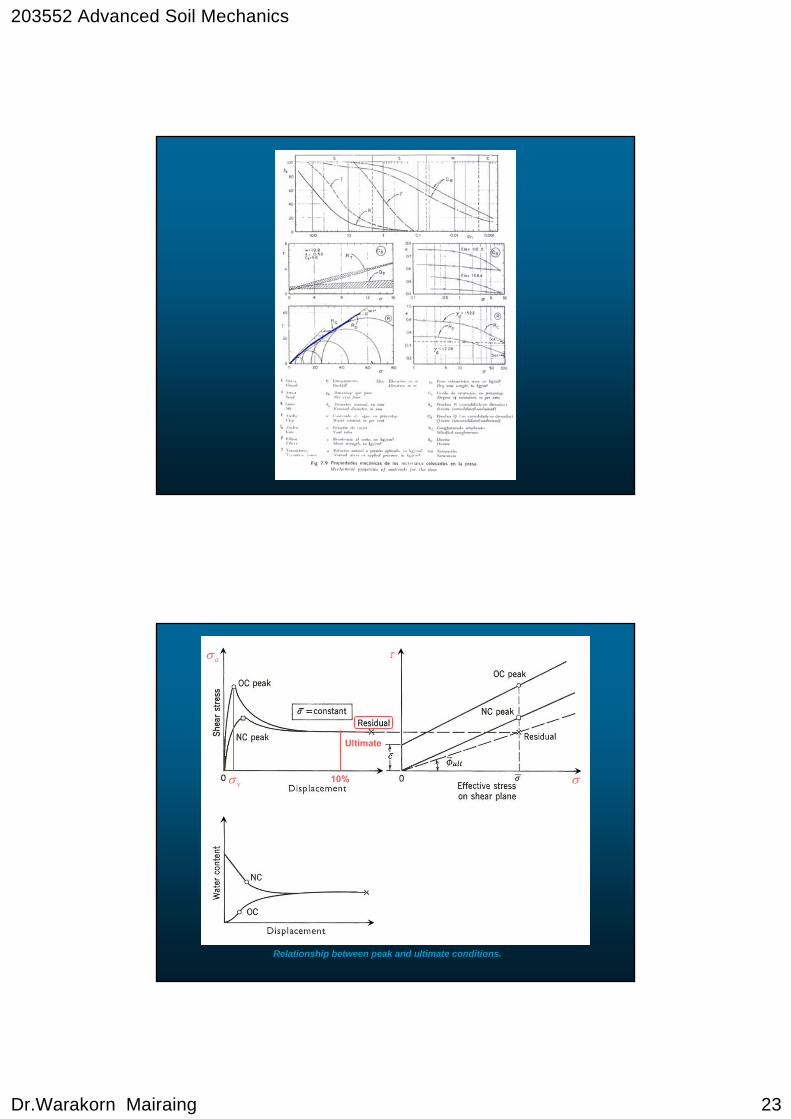
Relationship between peak and ultimate conditions.
τaσ
σvσ
Ultimate
10%

203552 Advanced Soil Mechanics
Dr.Warakorn Mairaing 24
Apparent Cohesion due to capillary
Effect of capillary tensions on effective stress and strength. (a) Sand. (b) Clay.
(a) Sand (b) Clay
aapp
Kf - lineCapillary rise
-u
203552 Advanced Soil Mechanics
Dr.Warakorn Mairaing 25
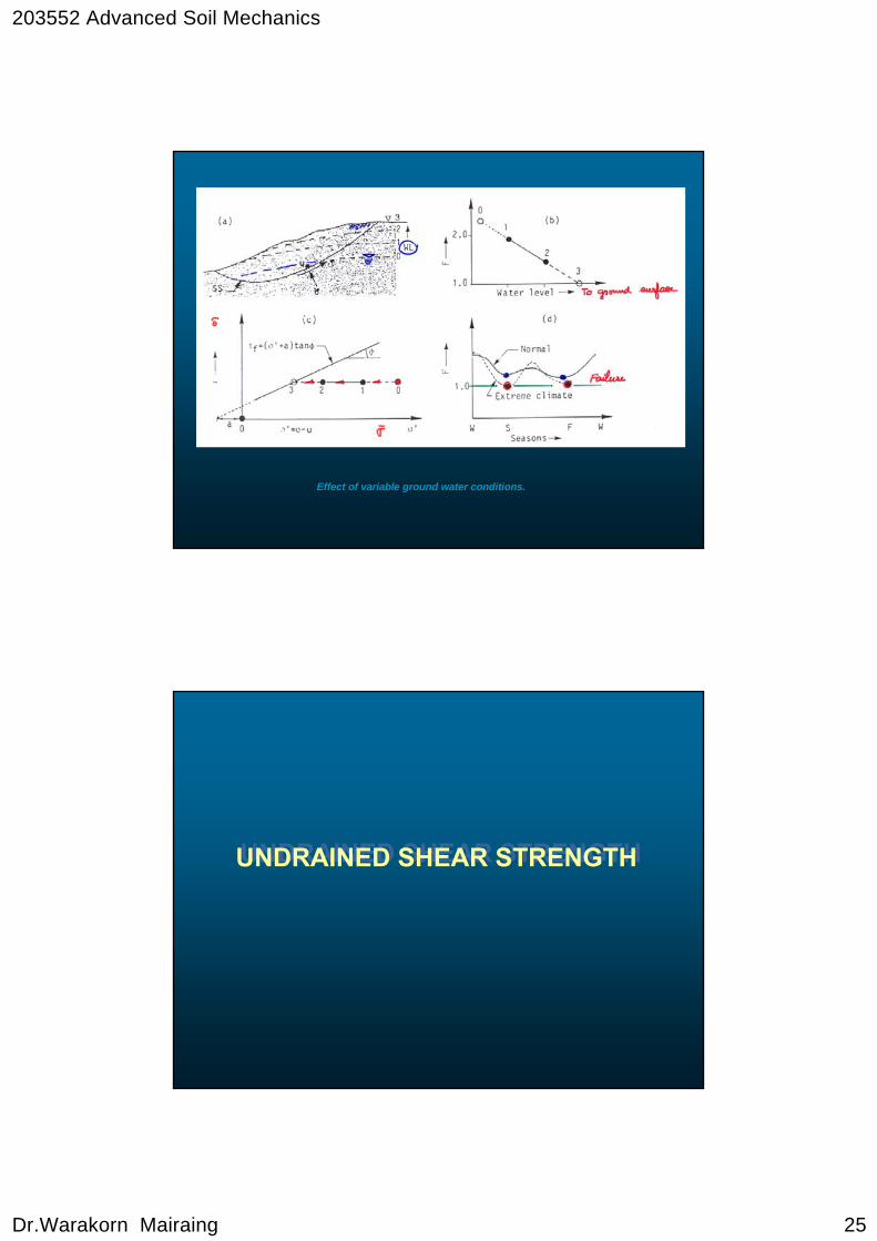
Effect of variable ground water conditions.
UNDRAINED SHEAR STRENGTHUNDRAINED SHEAR STRENGTH

203552 Advanced Soil Mechanics
Dr.Warakorn Mairaing 26
Sort strength is highly depended on the drainage condition in soil mass. During undrained condition when excess pore pressure is fully developed and no time to dissipate, the strength is called “undrained strength”
Normally, the undrained strength is lower than drained strength due to the present of pore pressure. The behavior of undrained strength can also explain by the theory of effective stress and represented by “Stress path”
1. Theoritical or laboratoryFully undrained conditions can be simulated.
2. Practical or fieldPartially drained condition is usually occurred.
Undrained Shear StrengthUndrained Shear Strength
We should consider the worst case for the design.
Loading drained strength higher then undrained strength is used.
Unloading drained strength is lowest.
203552 Advanced Soil Mechanics
Dr.Warakorn Mairaing 27
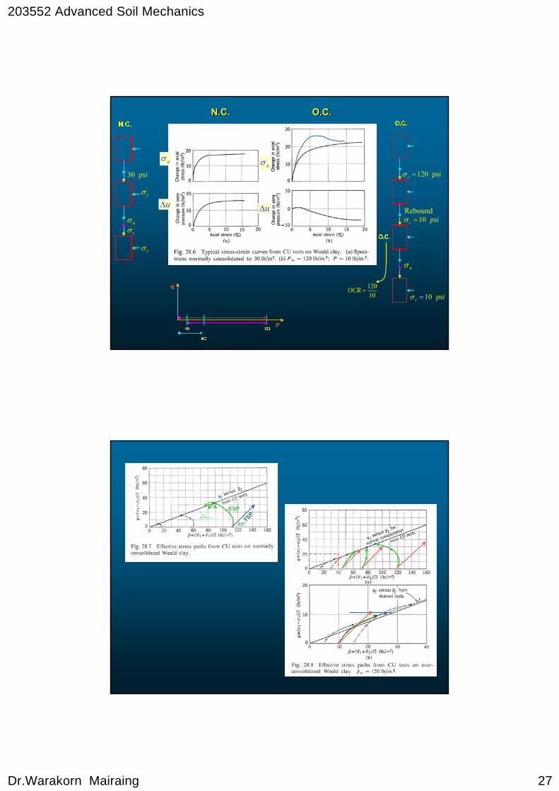
N.C.N.C. O.C.O.C.
uΔ
aσ
uΔ
aσ
cσ
cσ
cσ
psi30
aσ
psic 120=σ
Reboundpsic 10=σ
aσ
psic 10=σ10120
=OCR
TSP
ESP
450
203552 Advanced Soil Mechanics
Dr.Warakorn Mairaing 28
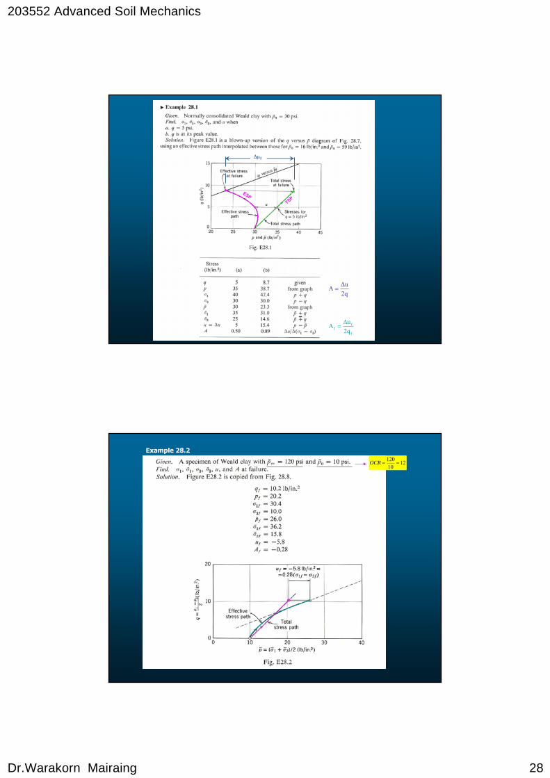
ESPTSP
Δμf
2qΔuA =
f
ff 2q
ΔuA =
1210120
==OCR
Example 28.2

203552 Advanced Soil Mechanics
Dr.Warakorn Mairaing 29
Bangkok Clay
Weald Clay
17 45fq fp
q
P60
(45,17)
Δu f = ?
TSPESP Af =0.94

203552 Advanced Soil Mechanics
Dr.Warakorn Mairaing 30
CD CU
CD
TSPESP
CU
Kf
Δu
30
CUA
CD
Wo = 23%
oP
CD Test
qf = 17.5 psi
from wf – qf –
find wf = 20.6%
wo = 23%
CU Test
qf = 8.5 psi
wf = 23%
q,q
ESP
TSP = ESP
P, P
E
CD (L)
C
A
D B
FCU
TSP
CU (L)TSP = ESP
CD (U)
TSPCU(U)
fK AB = ESP for Undrained T.A. -
Loading and Unloading.
AC = TSP for CU – Loading
AE = TSP = ESP for CD – Loading
AF = TSP = ESP for CD – Unloading
AD = TSP for CU – Unloading.
( )CU
Failure Level
203552 Advanced Soil Mechanics
Dr.Warakorn Mairaing 31
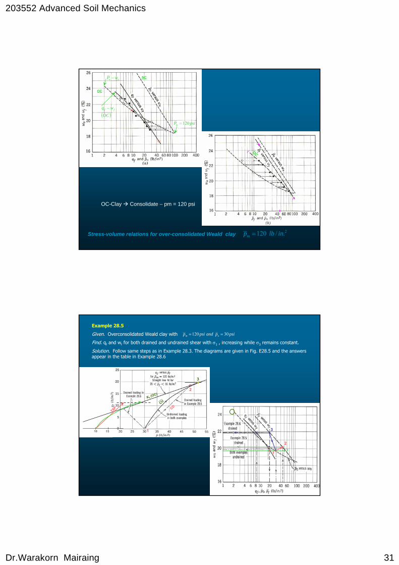
Stress-volume relations for over-consolidated Weald clay 2./120 inlbpm =
OC-Clay Consolidate – pm = 120 psi
x
_
_
OC
NC
OC
oo wP −
psiPm 120=
( )OC
wq ff −
Example 28.5
Given. Overconsolidated Weald clay with
Find. qf and wf for both drained and undrained shear with σ1 , increasing while σ3 remains constant.
Solution. Follow same steps as in Example 28.3. The diagrams are given in Fig. E28.5 and the answers appear in the table in Example 28.6
psipandpsip om 30120 ==
1
2
3
CDCU
TSP
Kf (OC)
1510
2
3
13
203552 Advanced Soil Mechanics
Dr.Warakorn Mairaing 32
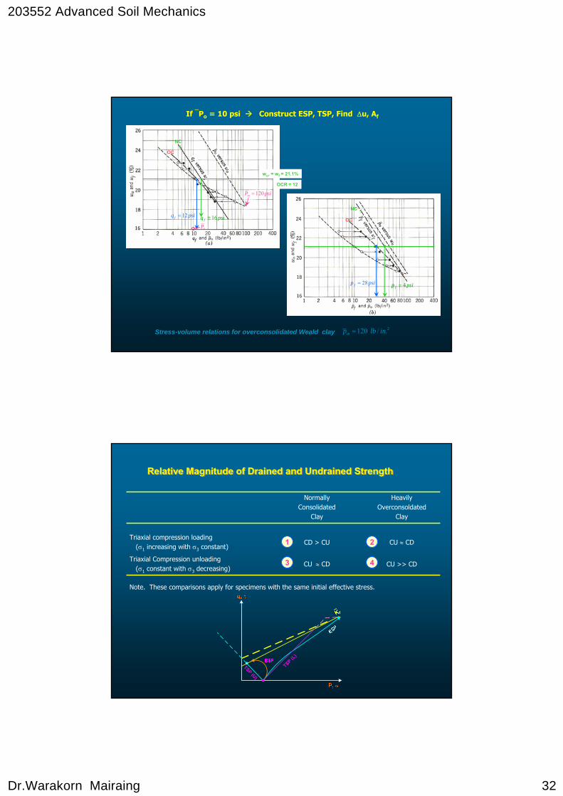
Stress-volume relations for overconsolidated Weald clay 2./120 inlbpm =
OC
NCx
psiPm 120=
wo, = wf = 21.1%
OCR = 12
psiq f 16≅
0P
psiq f 12=OC
NC x
psip f 4=psip f 28=
If ⎯Po = 10 psi Construct ESP, TSP, Find Δu, Af
TSP (L)
TSP (U)
Relative Magnitude of Drained and Undrained StrengthRelative Magnitude of Drained and Undrained Strength
Note. These comparisons apply for specimens with the same initial effective stress.
CU >> CDCU ≈ CDTriaxial Compression unloading
(σ1 constant with σ3 decreasing)
CU ≈ CDCD > CUTriaxial compression loading
(σ1 increasing with σ3 constant)
Heavily Overconsoldated
Clay
NormallyConsolidated
Clay
1
3
2
4
203552 Advanced Soil Mechanics
Dr.Warakorn Mairaing 33
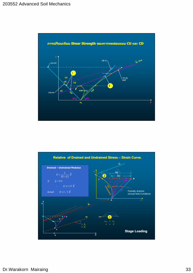
การเปรยีบเทยีบ Shear Strength ของการทดสอบแบบ CU และ CDการเปรยีบเทยีบ Shear Strength ของการทดสอบแบบ CU และ CD
TSPTSP
Relative of Drained and Undrained Stress – Strain Curve.Relative of Drained and Undrained Stress – Strain Curve.
q
TSP
P
ESP
Kf
BJ
(UNDRAINED)
A
Partially drained.(Actual field Condition)
Kf
K0
0
0
11
KK
+− Xe
vNO
→↓ 0σσ
1
2
Stage LoadingStage Loading
Drained – Undrained Modulus
( ) EE ⋅+
=μ123
3.0=μif
EE 15.1≅∴
EEActual 31−≈
203552 Advanced Soil Mechanics
Dr.Warakorn Mairaing 34
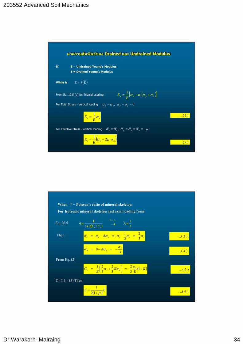
หาความสัมพนัธของ Drained และ Undrained Modulusหาความสัมพนัธของ Drained และ Undrained Modulus
If E = Undrained Young’s Modulus
E = Drained Young’s Modulus
While is ( )EfE =
From Eq. 12.5 (a) for Triaxial Loading ( )[ ]zyxx uE
E σσσ +−=1
For Total Stress - Vertical loading 0, === zyvx σσσσ
( )nvv EE σμσ 21
−=
For Effective Stress - vertical loading μσσσσσ −==== hzyvx ,
vv EE σ1= …( 1 )
…( 2 )
When = Poisson’s ratio of mineral skeleton.For Isotropic mineral skeleton and axial loading from
Eq. 26.5( ) 3
1/21
1=
+= →
=
ACC
Acs CC
cs
…( 3 )Thenvvvvvv A σσσσσσ
32
31
=−=−=
…( 4 )
…( 5 )
30 v
vh A σσσ −=−=
From Eq. (2)
( )μσσμσ +=⎟⎠⎞
⎜⎝⎛ += 1
32
32
321
EEG v
vvv
Or (1) = (5) Then
( ) EEμ+
=123
…( 6 )
u

203552 Advanced Soil Mechanics
Dr.Warakorn Mairaing 35
Final Strains are depended on stress-path
1. Larger ⎯p during loading cause smaller final strain (Ea)
2. Stress-path (ESP) closer to Kf - line cause larger final strain due to plastic + yielding behaviors.
Stress path before failure Elastic strain Plastic strain
Stress path close to failure Plastic + Yielding strain
CDCU
Consolidation
TSP 1 3
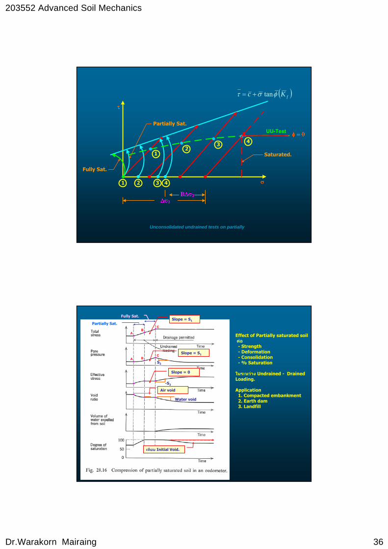
“UU” Fully Saturated Soil
TSP 2
c1c2
Su
Unconsolidated undrained tests on partially
203552 Advanced Soil Mechanics
Dr.Warakorn Mairaing 36
33
12
3 4
1 2 3 4
UU-Test
Fully Sat.
Partially Sat.
Saturated.
Unconsolidated undrained tests on partially
( )fKc φστ tan+=
Effect of Partially saturated soil ตอ- Strength- Deformation- Consolidation- % Saturation
ในระหวาง Undrained - Drained Loading.
Application1. Compacted embankment2. Earth dam3. Landfill
AB
C
Slope = S1Fully Sat.
Partially Sat.
A BC
Slope = S1
S2
-S2
Slope = 0
Air void
Water void
เทียบ Initial Void.
203552 Advanced Soil Mechanics
Dr.Warakorn Mairaing 37
Undrained Shear StrengthUndrained Shear Strength
1. Undrained Shear Strength of Saturated Sand
Undrained loading on saturated sand during fast or repeated loading conditions
Generally
1. Loose sand similar to N.C. or Soft Clay
2. Dense sand similar to O.C. or Stiff Clay
Exception
For loose sand after peak, soil can maintain it failure condition and pore pressure start to decrease due to dilatency effect.
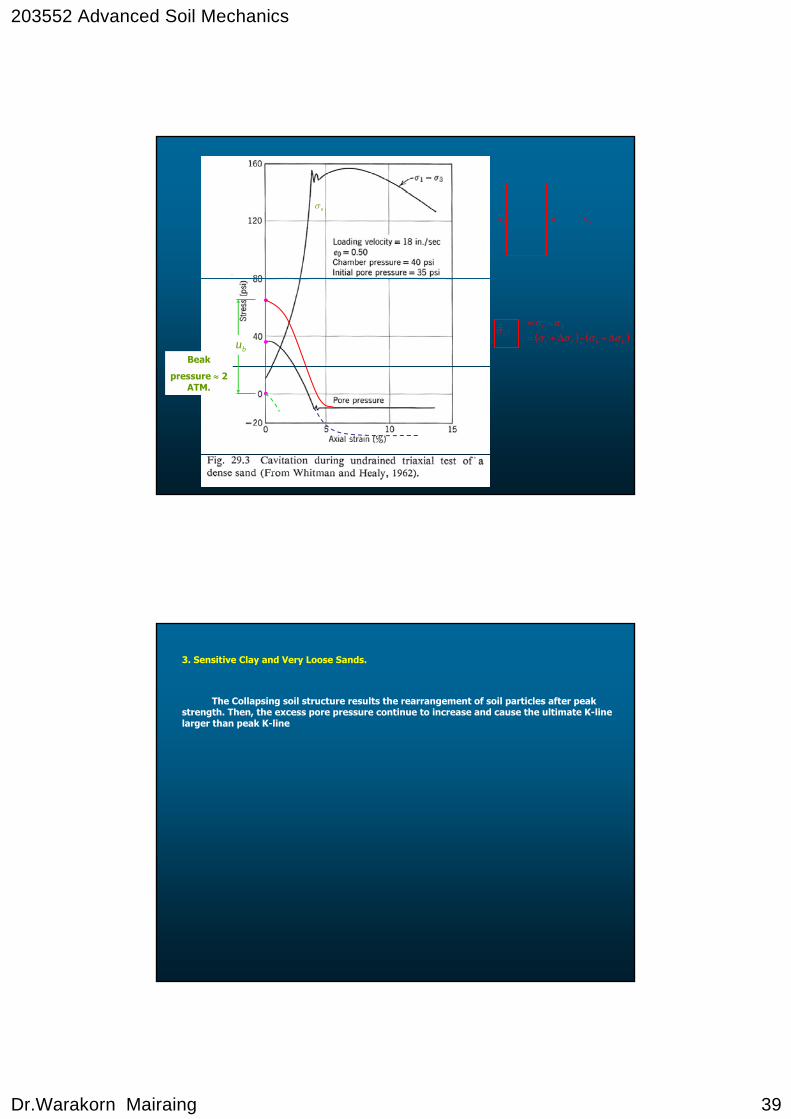
2. Cavitation of Pore Water
For dense sand during searing, soil mass tend to expound and develop negative pore pressure.
If u < -1.0 ATM. (-14.4 psi), then pore water will cavilate
Solution
Back pressure of about 1 ATM (or more) is applied in soil sample and confining pressure.
203552 Advanced Soil Mechanics
Dr.Warakorn Mairaing 38
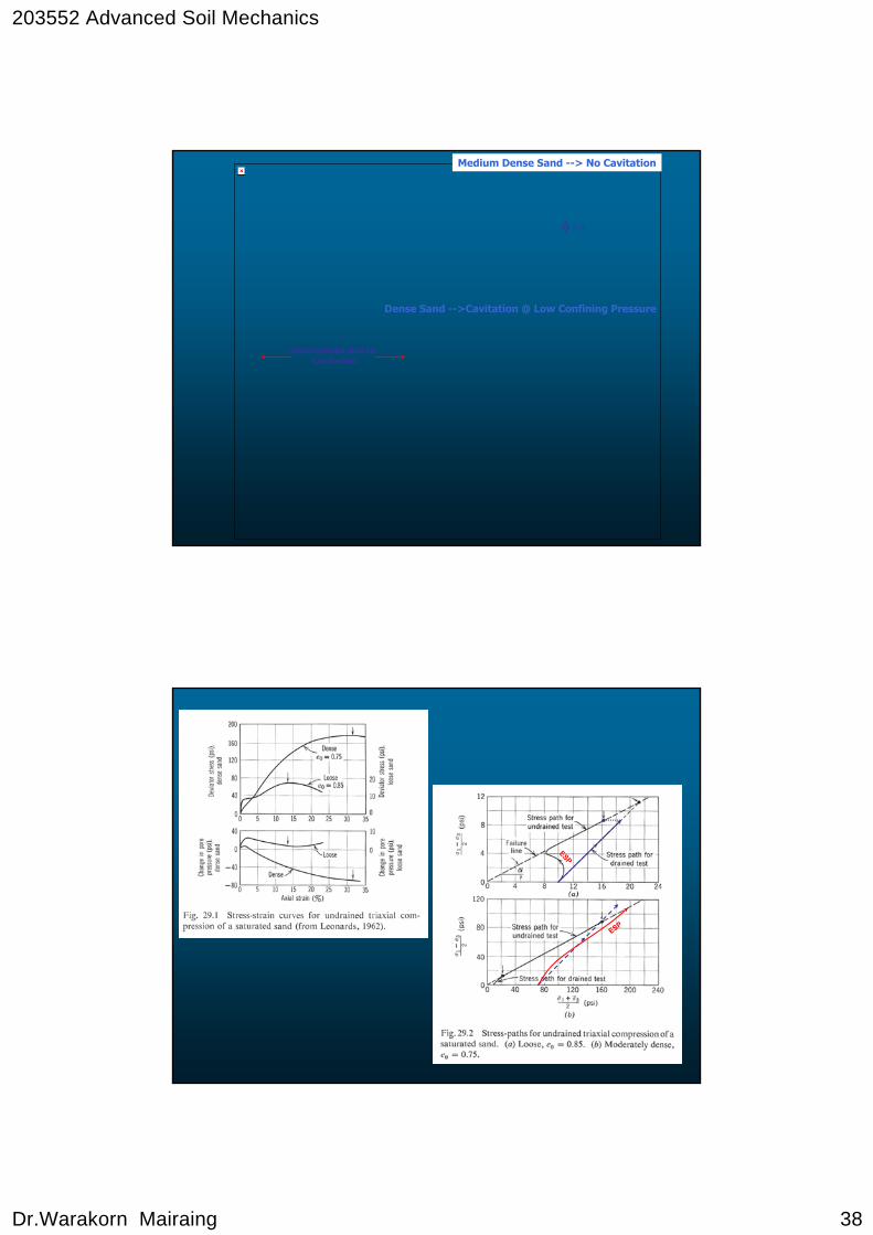
Medium Dense Sand --> No Cavitation
Dense Sand -->Cavitation @ Low Confining Pressure
Unsaturated due tocavitation
φ = 0
ESP
ESP
203552 Advanced Soil Mechanics
Dr.Warakorn Mairaing 39
Beak
pressure ≈ 2ATM.
bu
aσ
bσ cσ
cσ ( ) ( )bbcc
bc
σσσσσσ
Δ+−Δ+=−=
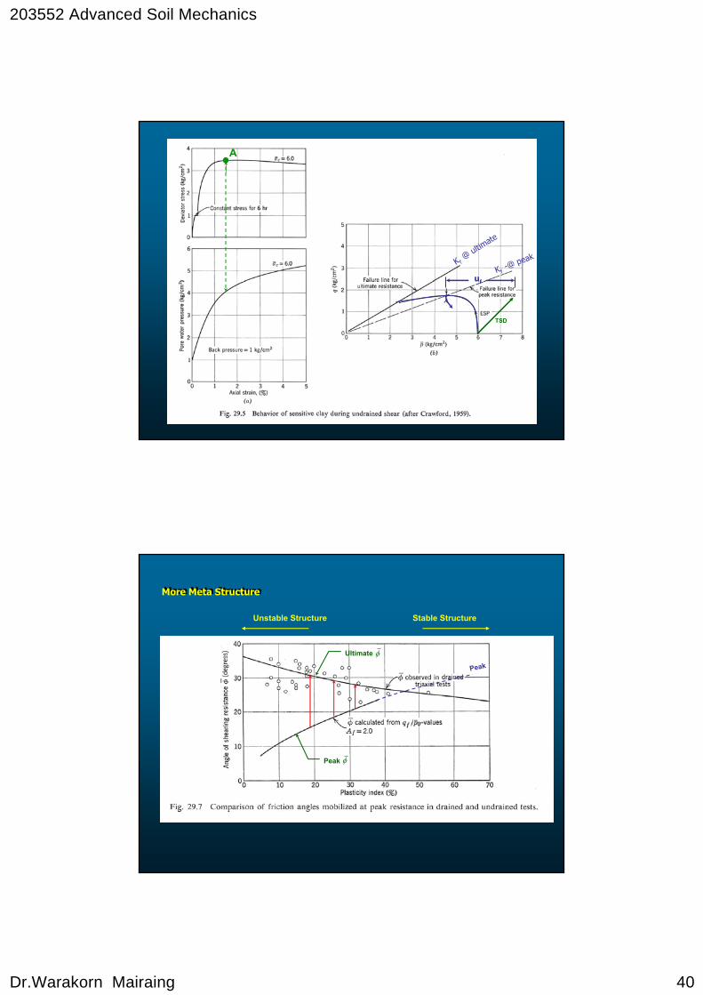
3. Sensitive Clay and Very Loose Sands.
The Collapsing soil structure results the rearrangement of soil particles after peak strength. Then, the excess pore pressure continue to increase and cause the ultimate K-line larger than peak K-line
203552 Advanced Soil Mechanics
Dr.Warakorn Mairaing 40
A
uf
TSD
K f@
ultimate
Kf-@ peak
More Meta StructureMore Meta Structure
Stable StructureUnstable Structure
Peak φ
Peak
Ultimate φ
203552 Advanced Soil Mechanics
Dr.Warakorn Mairaing 41
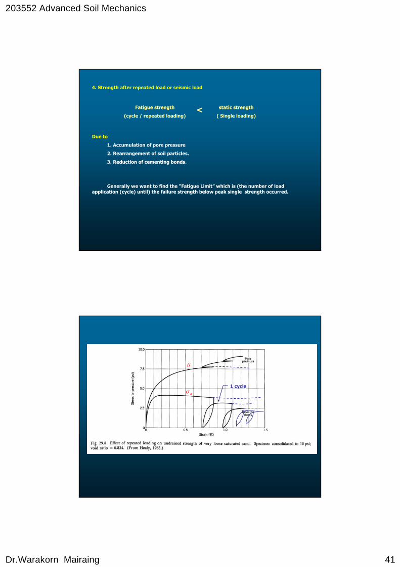
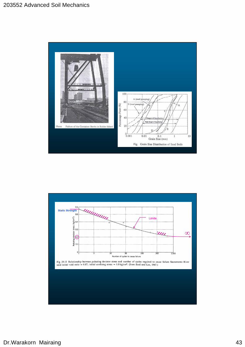
4. Strength after repeated load or seismic load
Due to
1. Accumulation of pore pressure
2. Rearrangement of soil particles.
3. Reduction of cementing bonds.
Fatigue strength
(cycle / repeated loading)
static strength
( Single loading)<
Generally we want to find the “Fatigue Limit” which is (the number of load application (cycle) until) the failure strength below peak single strength occurred.
μ
aσ1 cycle
203552 Advanced Soil Mechanics
Dr.Warakorn Mairaing 42
203552 Advanced Soil Mechanics
Dr.Warakorn Mairaing 43
Static Strength
∞
Limite
203552 Advanced Soil Mechanics
Dr.Warakorn Mairaing 44
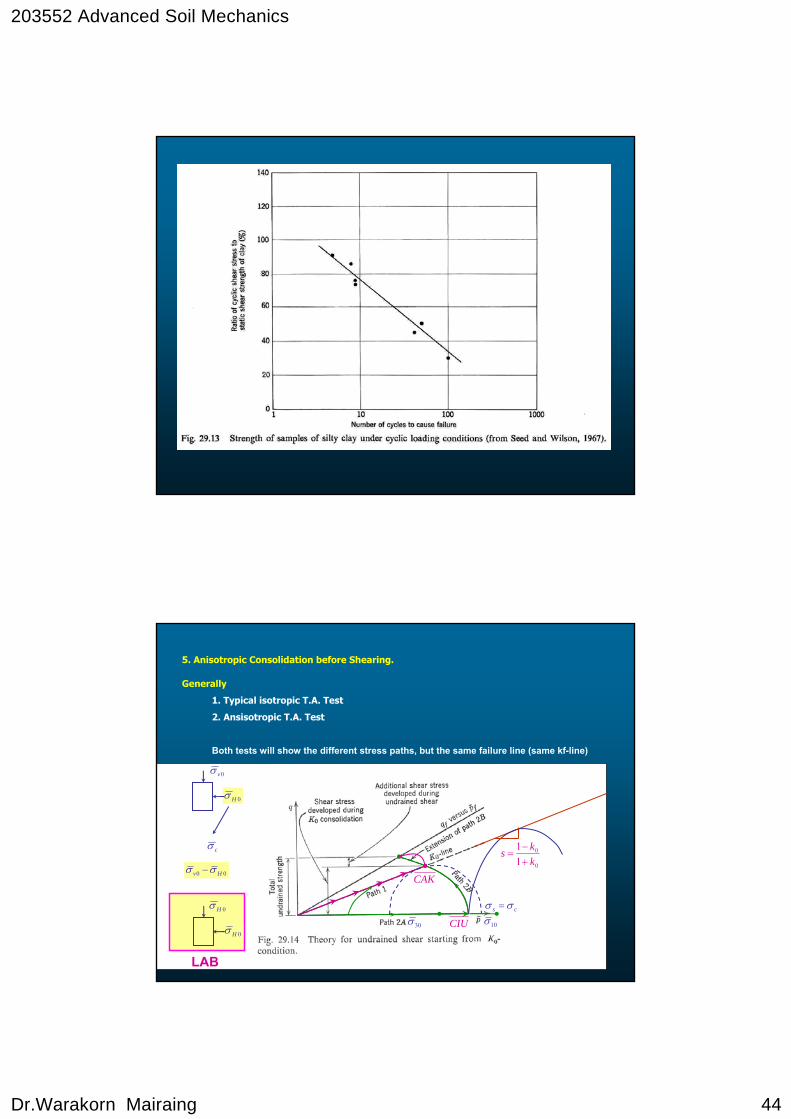
5. Anisotropic Consolidation before Shearing.
Generally
1. Typical isotropic T.A. Test
2. Ansisotropic T.A. Test
Both tests will show the different stress paths, but the same failure line (same kf-line)
30σ CIU
CAK0
0
11
kks
+−
=
10σcs σσ =
0Hσ
0vσ
cσ
00 Hv σσ −
0Hσ
0Hσ
LAB
203552 Advanced Soil Mechanics
Dr.Warakorn Mairaing 45
psP
ESP
)( peakk fUltimate strength
peak
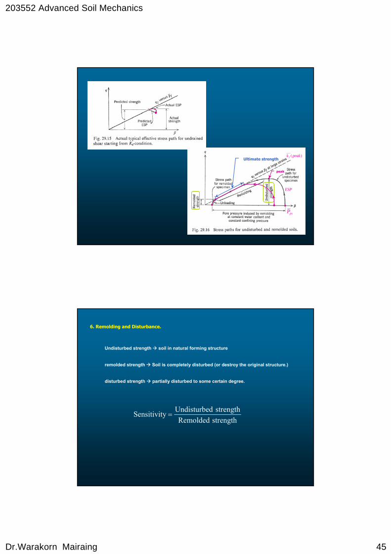
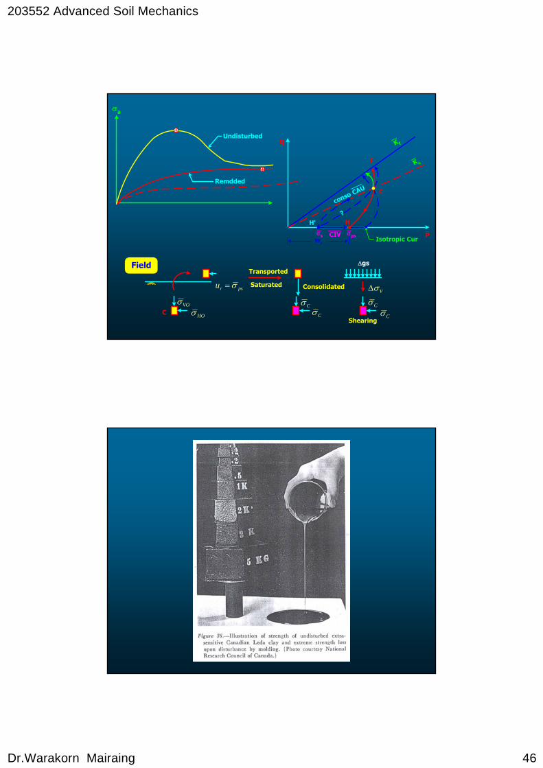
6. Remolding and Disturbance.
Undisturbed strength soil in natural forming structure
remolded strength Soil is completely disturbed (or destroy the original structure.)
disturbed strength partially disturbed to some certain degree.
strengthRemoldedstrengthdUndisturbeySensitivit =
203552 Advanced Soil Mechanics
Dr.Warakorn Mairaing 46
Field
C
Transported
Saturated Consolidated
Shearing
Δgs
VOσHOσ Cσ
Cσ CσCσ
VσΔpsru σ=
q
Pwr
C
F
HH'?
conso CAU
Isotropic Curσpsσs CIV
K f
K c
σa
Undisturbed
Remdded

203552 Advanced Soil Mechanics
Dr.Warakorn Mairaing 47
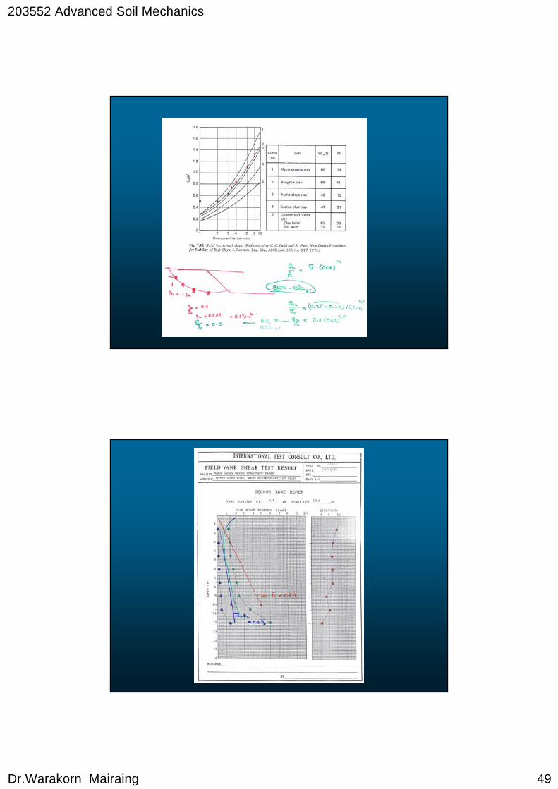
7. Stress History
- Overconsolidated OC
- Normally Consolidated NC
Normalized undrained strength by SHANSEP
qfqfm
Po / Pm
1
1
NC
OC
SHANSEP Theory by Ladd and Foott (1974)SHANSEP Theory by Ladd and Foott (1974)
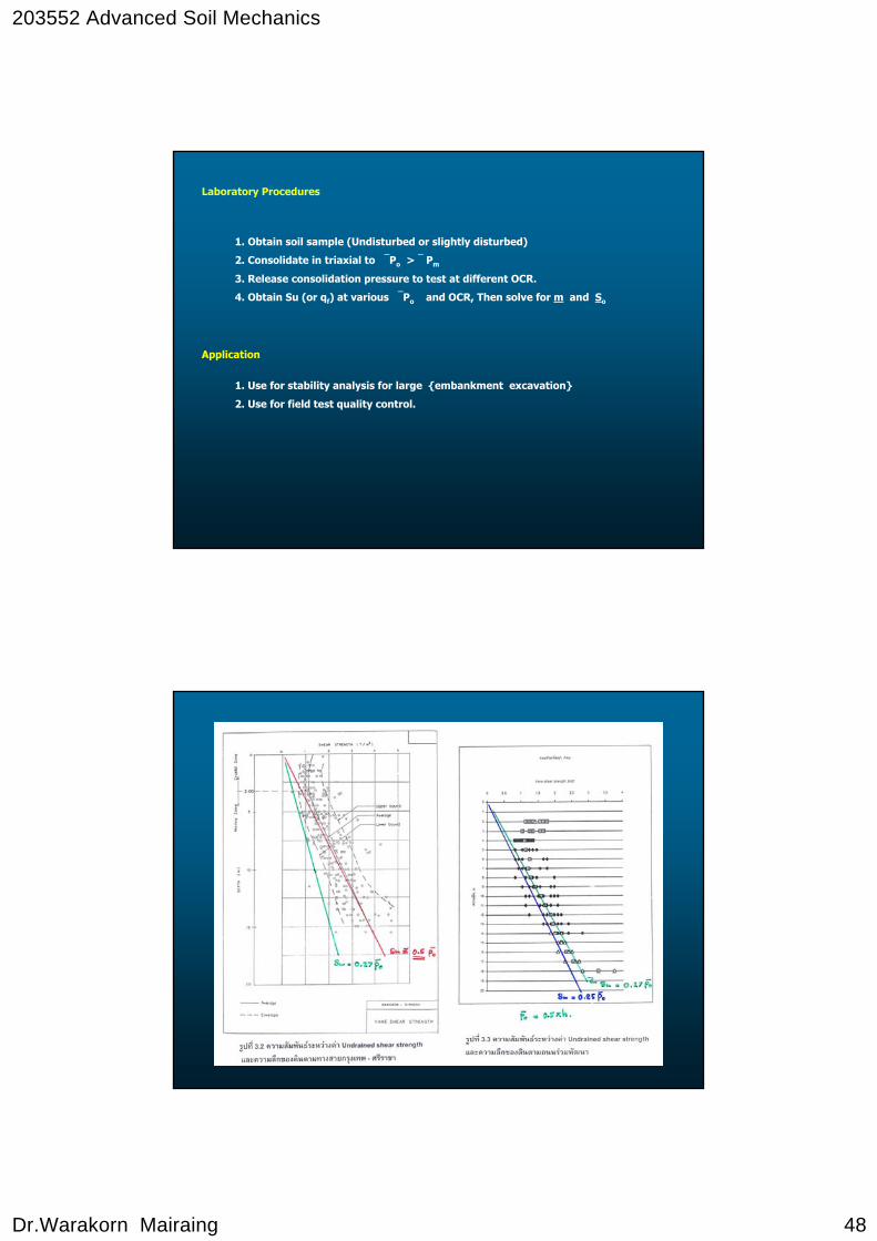
Stress History And Normalized Soil Engineering Properties
When clayey soil is naturally sedimented or artificially sedimented in laboratory. The undrained shear strength (Su) is proportioned to ⎯Po as
( )mo
o
u OCRSPS
⋅= …( 1 )
When @ Normally Consolidation State (OCR = 1)
o
uo P
SS =
For Bangkok Clay So ≈ 0.25
m = Constant ≈ 0.8 ± 0.05
OCR = Overconsolidation Ratio
203552 Advanced Soil Mechanics
Dr.Warakorn Mairaing 48
Laboratory Procedures
1. Obtain soil sample (Undisturbed or slightly disturbed)
2. Consolidate in triaxial to ⎯Po > ⎯ Pm
3. Release consolidation pressure to test at different OCR.
4. Obtain Su (or qf) at various ⎯Po and OCR, Then solve for m and So
Application
1. Use for stability analysis for large {embankment excavation}
2. Use for field test quality control.
203552 Advanced Soil Mechanics
Dr.Warakorn Mairaing 49

203552 Advanced Soil Mechanics
Dr.Warakorn Mairaing 50
Table : Common Methods for Measuring undrained Strength
Best general purpose test; underestimates strength because disturbance decreases effective stress
1. Unconfined compression
Measurements upon undisturbed samples
Usually considered to give best result, but is limited as to strength of soil with which it can be used
1. Vane test
In-situ measurements
CommentMethod
Overestimates strength, because disturbance leads to smaller water content upon reconsolidation
3. CU test at in situ confining pressure
Most representative of laboratory tests, because of compensating errors.
2. UU test at in situ confining pressure
3. Static Conre Pure Test (CPT)
Gives crude correlation to strength2. Soft to Medium Penetration test (SPT)
STRESS – STRAIN RELATIONSHOP FOR CU STRESS – STRAIN RELATIONSHOP FOR CU
Applications
1. Immediate Settlement of Loaded Area
2. Movement of Tunnel in soil
3. Excavation heaving and lateral movement
Parameters
- Young’s Modulus, E (Elastic modulus)
- Shear modulus, G
- Poisson’s Raton, μ or υ
From Eq. 12.4
( )μ+=
12EG …( 1 )
203552 Advanced Soil Mechanics
Dr.Warakorn Mairaing 51
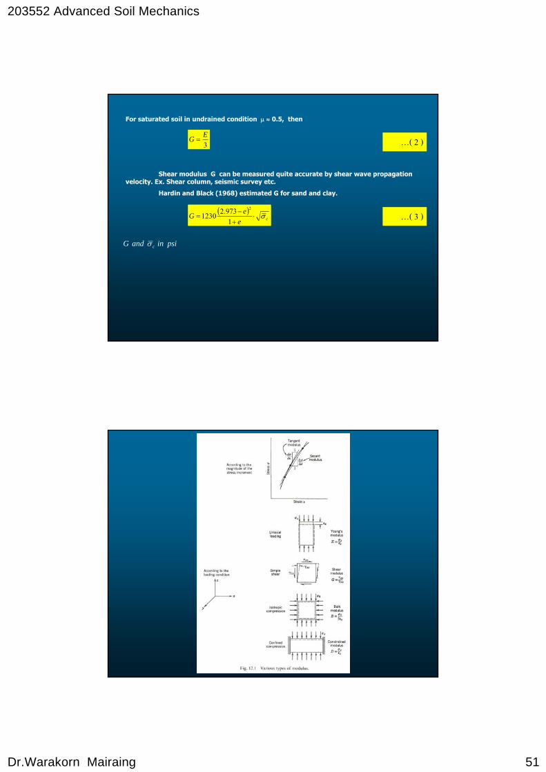
3EG = …( 2 )
For saturated soil in undrained condition μ ≈ 0.5, then
Shear modulus G can be measured quite accurate by shear wave propagation velocity. Ex. Shear column, seismic survey etc.
Hardin and Black (1968) estimated G for sand and clay.
( )ce
eG σ⋅+
−=
1973.21230
2
…( 3 )
psiinandG cσ
203552 Advanced Soil Mechanics
Dr.Warakorn Mairaing 52
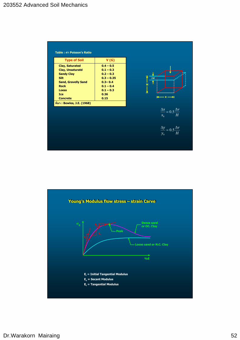
Table : คา Poisson’s Ratio
ท่ีมา : Bowles, J.E. (1968)
0.4 – 0.50.1 – 0.30.2 – 0.30.3 – 0.350.3– 0.40.1 – 0.40.1 – 0.30.360.15
Clay, SaturatedClay, UnsaturatdSandy ClaySiltSand, Gravelly SandRockLoessIceConcrete
V (G)Type of Soil
Hv
yy Δ
=Δ 5.00
Hv
xx Δ
=Δ 5.00
x
H
Δv
Young’s Modulus flow stress – strain Carve Young’s Modulus flow stress – strain Carve
Ei = Initial Tangential Modulus
Es = Secant Modulus
Et = Tangential Modulus
σa
%E
Peak
Loose sand or N.C. Clay
Dense sandor OC. Clay
Ei
Es
Et
203552 Advanced Soil Mechanics
Dr.Warakorn Mairaing 53
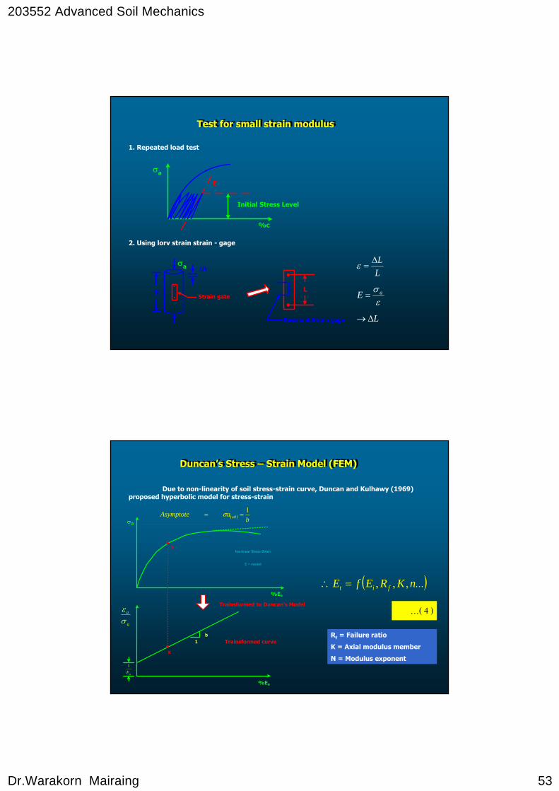
Test for small strain modulusTest for small strain modulus
1. Repeated load test
2. Using lorv strain strain - gage
σa
%c
E
Initial Stress Level
εσ aE =
LLΔ
=ε
hStrain gate
σa Δh
L
Resistant Strain gage LΔ→
a
%Ea
Nonlinear Stress-Strain
E = vasied
Trainsformed curve
Trainsformed to Duncan's Model
1b
x
%Ea
x
a
a
σε
( ) baAsymptote utl
1== σ
aE1
Duncan’s Stress – Strain Model (FEM)Duncan’s Stress – Strain Model (FEM)
Due to non-linearity of soil stress-strain curve, Duncan and Kulhawy (1969) proposed hyperbolic model for stress-strain
( )...,,, nKREfE fit =∴
…( 4 )
Rf = Failure ratio
K = Axial modulus member
N = Modulus exponent
203552 Advanced Soil Mechanics
Dr.Warakorn Mairaing 54
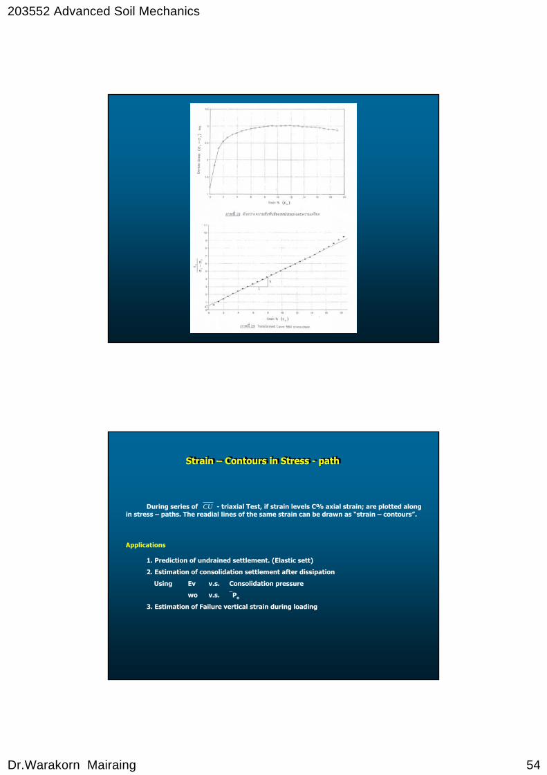
Strain – Contours in Stress - pathStrain – Contours in Stress - path
During series of - triaxial Test, if strain levels C% axial strain; are plotted along in stress – paths. The readial lines of the same strain can be drawn as “strain – contours”.
Applications
1. Prediction of undrained settlement. (Elastic sett)
2. Estimation of consolidation settlement after dissipation
Using Ev v.s. Consolidation pressure
wo v.s. ⎯Po
3. Estimation of Failure vertical strain during loading
CU
203552 Advanced Soil Mechanics
Dr.Warakorn Mairaing 55
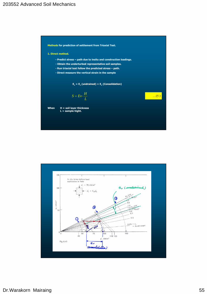
Methods for prediction of settlement from Triaxial Test.
1. Direct method.
- Predict stress – path due to insitu and construction loadings.
- Obtain the underturbed representative soil samples.
- Run triaxial test follow the predicted stress – path.
- Direct measure the vertical strain in the sample
Ev = Ev (undrained) + Ev (Consolidation)
LHEvS ⋅= …(5 )
When H = soil layer thicknessL = sample hight.
203552 Advanced Soil Mechanics
Dr.Warakorn Mairaing 56
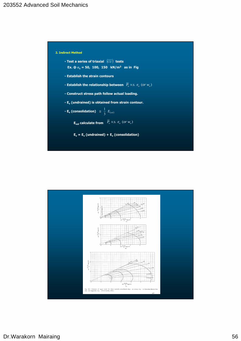
2. Indirect Method
- Test a series of triaxial tests
Ex. @ σc = 50, 100, 150 kN/m3 as in Fig
- Establish the strain contours
- Establish the relationship between
- Construct stress path follow actual loading.
- Ev (undrained) is obtained from strain contour.
- Ev (consolidation)
Evol calculate from
Ev = Ev (undrained) + Ev (consolidation)
( )CU
)(.. ooo woresvP
)(.. ooo woresvP
( )volE31
≅
203552 Advanced Soil Mechanics
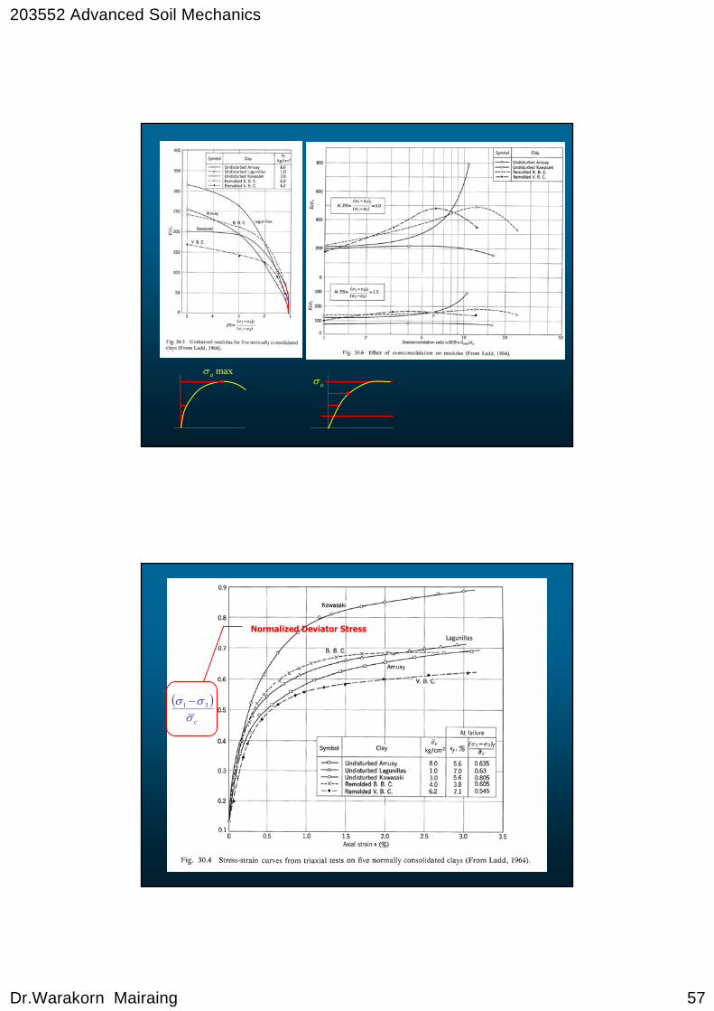
Dr.Warakorn Mairaing 57
maxaσaσ
Normalized Deviator Stress
( )cσσσ 31 −
203552 Advanced Soil Mechanics
Dr.Warakorn Mairaing 58
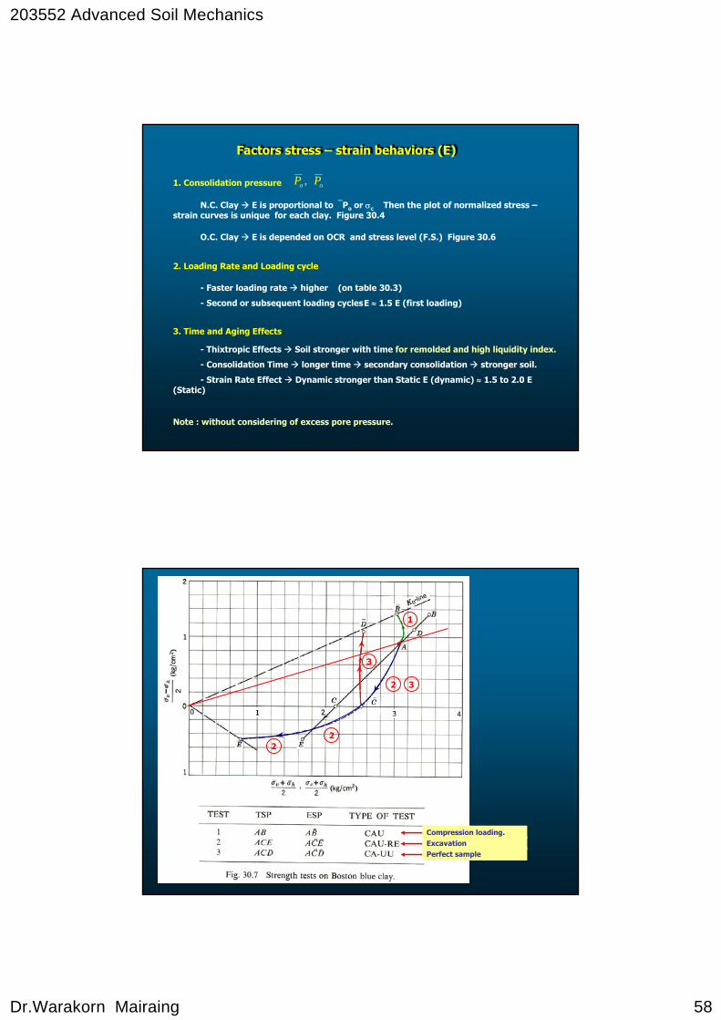
Factors stress – strain behaviors (E)Factors stress – strain behaviors (E)
1. Consolidation pressure
N.C. Clay E is proportional to ⎯Po or σc Then the plot of normalized stress –strain curves is unique for each clay. Figure 30.4
oo PP ,
O.C. Clay E is depended on OCR and stress level (F.S.) Figure 30.6
2. Loading Rate and Loading cycle
- Faster loading rate higher (on table 30.3)
- Second or subsequent loading cyclesE ≈ 1.5 E (first loading)
3. Time and Aging Effects
- Thixtropic Effects Soil stronger with time for remolded and high liquidity index.
- Consolidation Time longer time secondary consolidation stronger soil.
- Strain Rate Effect Dynamic stronger than Static E (dynamic) ≈ 1.5 to 2.0 E (Static)
Note : without considering of excess pore pressure.
ExcavationCompression loading.
Perfect sample
1
2 3
3
22
203552 Advanced Soil Mechanics
Dr.Warakorn Mairaing 59
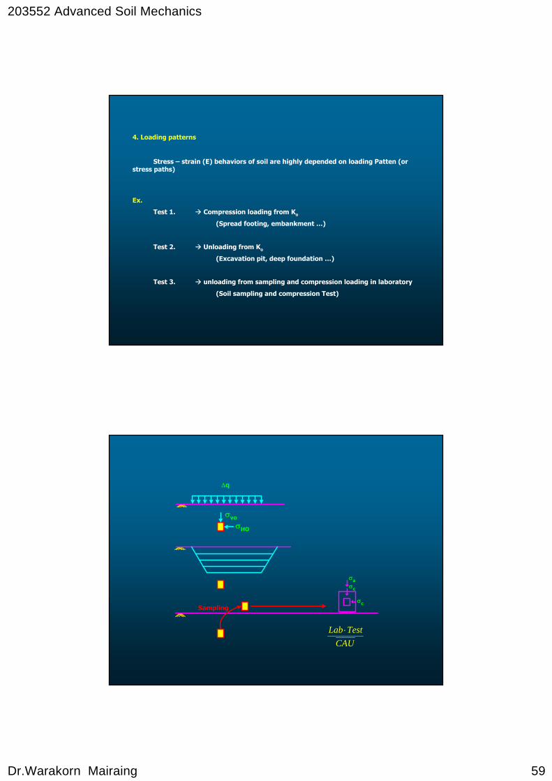
4. Loading patterns
Stress – strain (E) behaviors of soil are highly depended on loading Patten (or stress paths)
Ex.
Test 1. Compression loading from Ko
(Spread footing, embankment …)
Test 2. Unloading from Ko
(Excavation pit, deep foundation …)
Test 3. unloading from sampling and compression loading in laboratory
(Soil sampling and compression Test)
σHO
σvo
Δq
Sampling
σa
σc
σc
CAUTestLab ⋅
203552 Advanced Soil Mechanics
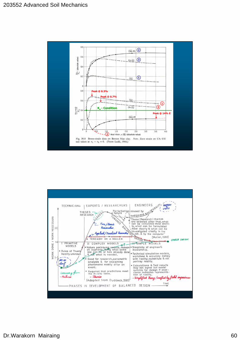
Dr.Warakorn Mairaing 60
Peak @ 0.3%
Peak @ 0.7%
Peak @ 14% E
Ko - Condition 3
2
1
3
2
1
203552 Advanced Soil Mechanics
Dr.Warakorn Mairaing 61
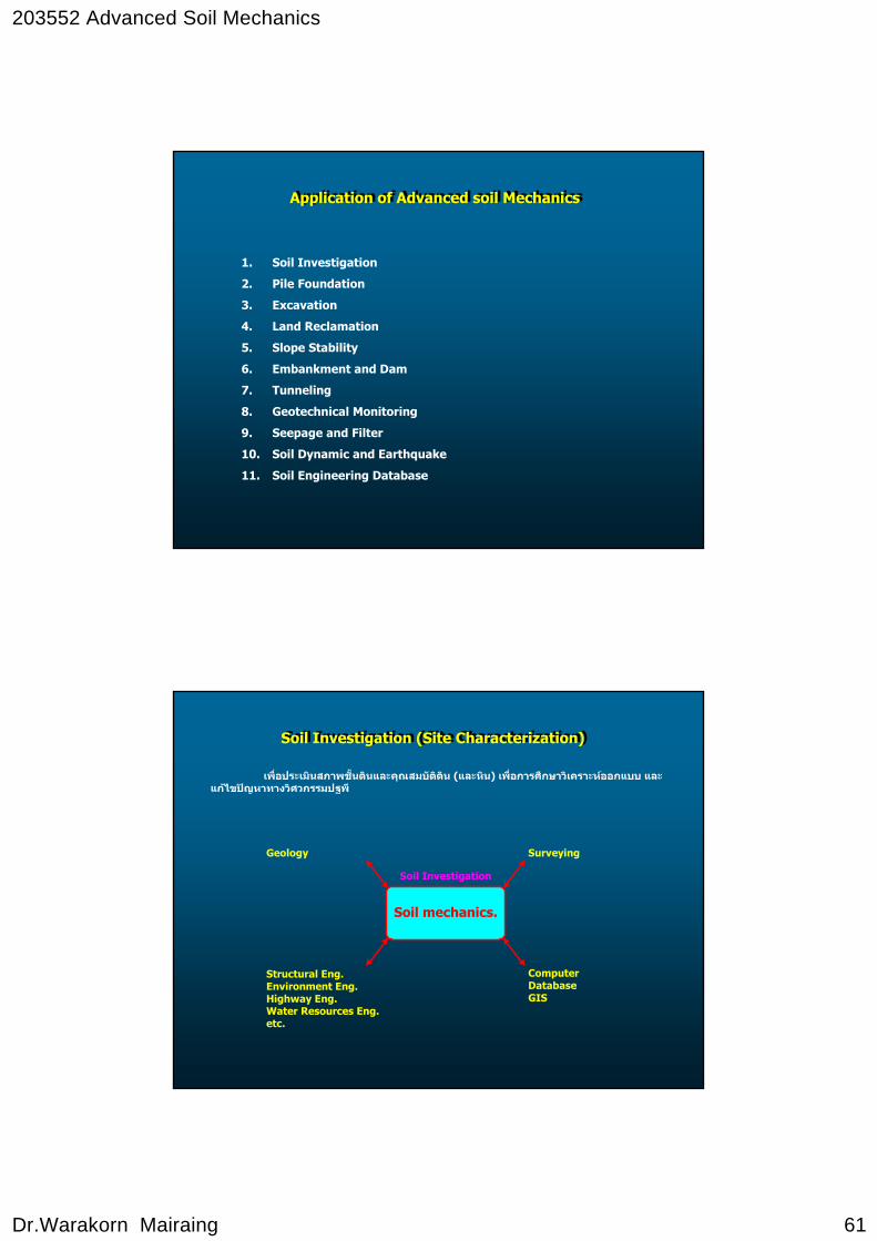
Application of Advanced soil MechanicsApplication of Advanced soil Mechanics
1. Soil Investigation
2. Pile Foundation
3. Excavation
4. Land Reclamation
5. Slope Stability
6. Embankment and Dam
7. Tunneling
8. Geotechnical Monitoring
9. Seepage and Filter
10. Soil Dynamic and Earthquake
11. Soil Engineering Database
Soil Investigation (Site Characterization)Soil Investigation (Site Characterization)
เพื่อประเมินสภาพชัน้ดินและคุณสมบัติดิน (และหิน) เพื่อการศึกษาวิเคราะหออกแบบ และแกไขปญหาทางวิศวกรรมปฐพี
Soil mechanics.
Geology Surveying
Structural Eng.Environment Eng.Highway Eng.Water Resources Eng.etc.
ComputerDatabaseGIS
Soil Investigation
203552 Advanced Soil Mechanics
Dr.Warakorn Mairaing 62
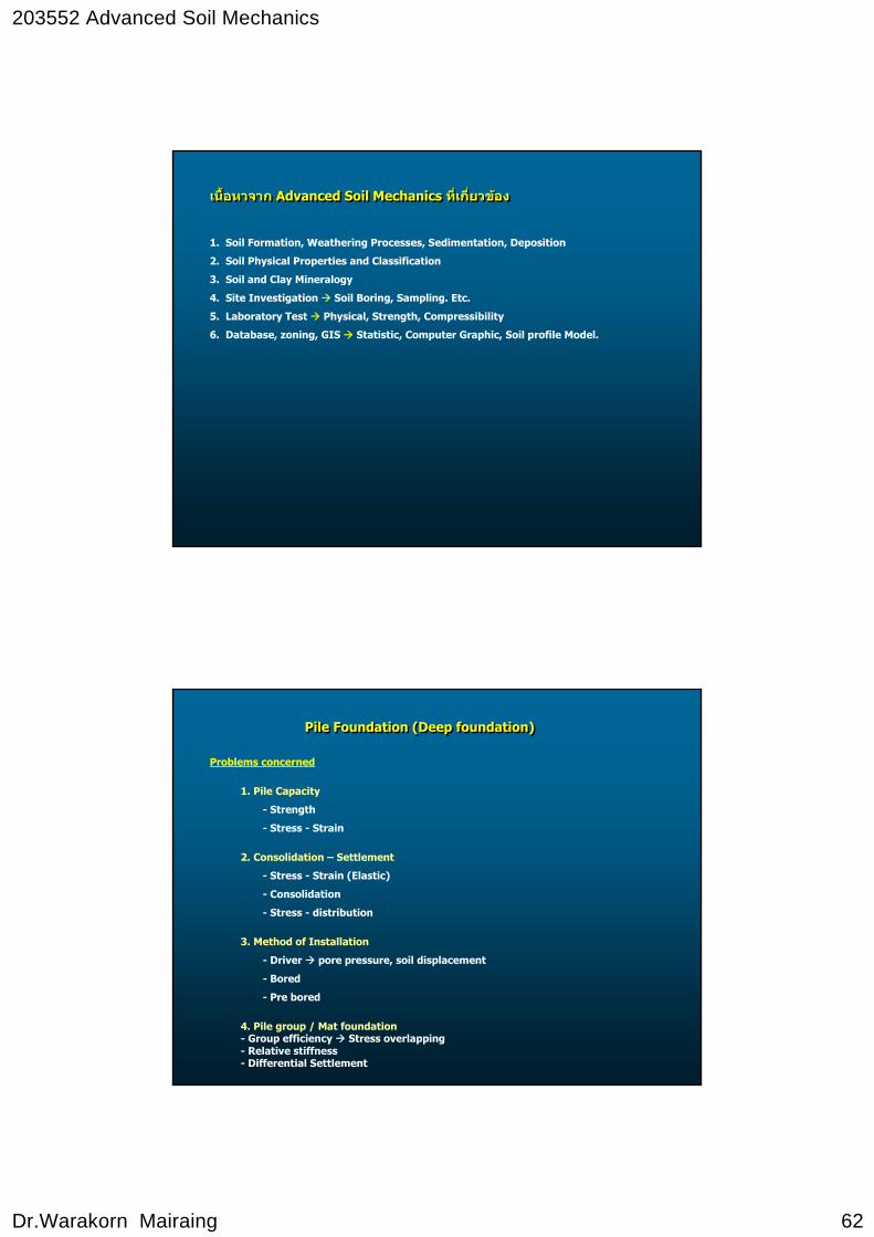
เนื้อหาจาก Advanced Soil Mechanics ท่ีเกี่ยวของเนื้อหาจาก Advanced Soil Mechanics ท่ีเกี่ยวของ
1. Soil Formation, Weathering Processes, Sedimentation, Deposition
2. Soil Physical Properties and Classification
3. Soil and Clay Mineralogy
4. Site Investigation Soil Boring, Sampling. Etc.
5. Laboratory Test Physical, Strength, Compressibility
6. Database, zoning, GIS Statistic, Computer Graphic, Soil profile Model.
Pile Foundation (Deep foundation)Pile Foundation (Deep foundation)
Problems concerned
1. Pile Capacity
- Strength
- Stress - Strain
2. Consolidation – Settlement
- Stress - Strain (Elastic)
- Consolidation
- Stress - distribution
3. Method of Installation
- Driver pore pressure, soil displacement
- Bored
- Pre bored
4. Pile group / Mat foundation- Group efficiency Stress overlapping- Relative stiffness- Differential Settlement

203552 Advanced Soil Mechanics
Dr.Warakorn Mairaing 63
5. Caisson / Shaft- End bearing- Seepage- Horizontal pressure , Friction
6. Bored pile / Barrette Wall (Slurry)- Bentonite properties- Trench Stability- Seepage.
7. TunnelingProblem 1. Strength
2. Insitu – Stress, Stress Release3. Seepage4. Rock bolting – Soil nailing, living5. Blasting, Tunneling machine
σa
%c
Δv
σvoσΗο
σvo
8. Geotechnical monitoring Problem 1. Pore pressure
2. Stress, load3. Movements4. Temperature5. Permeability
9. ExcavationProblem 1. Soil Strength - Stability
2. Seepage3. Lateral earth pressure – lateral movement.4. Pressure relief - heaving
10. Land ReclamationProblem 1. Settlement
2. Soil Strength - Stability3. Compaction - Soil improvement
11. Slope Stability (Natural – Manmade)Problem 1. Soil Strength
2. Pore pressure – drainage - infiltration3. Erosion
12. Embankment and DamsProblem 1. Soil strength
2. Compaction3. Seepage - drainage4. Settlement
203552 Advanced Soil Mechanics
Dr.Warakorn Mairaing 64
13. Seepage and FilterProblem 1.
14. Soil Dynamic and EarthquakeProblem 1.
15. Soil Engineering DatabaseProblem 1.
Design Pile FoundationDesign Pile Foundation
Pile Types
1. Short pile (3-12 m)
Timber, R/C
2. Long P/C pile
Section 15 62.5 cm.
Length 26 m. Maximum
3. Bored Pile
- Dry Process d = 35 200 cm.
- Wet Process
- Micro pile (grouting technique)
4. Steel Pile
203552 Advanced Soil Mechanics
Dr.Warakorn Mairaing 65
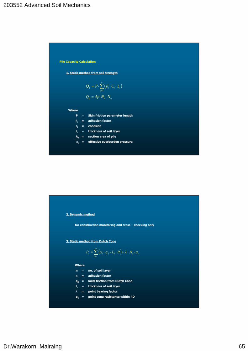
1. Static method from soil strength
Where
P = Skin friction parameter length
βi = adhesion factor
ci = cohesion
Li = thickness of soil layer
Ap = section area of pile
⎯σv = effective overburden pressure
( )∑=
⋅⋅⋅=n
iiiif LCPQ
1
β
qvp NApQ ⋅⋅= σ
Pile Capacity Calculation
2. Dynamic method
- for construction monitoring and cross – checking only
3. Static method from Dutch Cone
( ) cp
n
iifiiu qAPLqP ⋅⋅+⋅⋅⋅= ∑
=
λα1
Where
n = no. of soil layer
αi = adhesion factor
qfi = local friction from Dutch Cone
Li = thickness of soil layer
λ = point bearing factor
qc = point cone resistance within 4D
203552 Advanced Soil Mechanics
Dr.Warakorn Mairaing 66
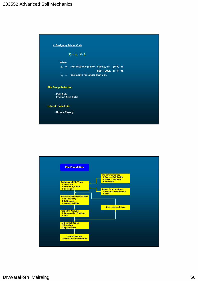
4. Design by B.M.A. Code
LPqP fa ⋅⋅=
When
qf = skin friction equal to 800 kg/m2 (0-7) m.
800 + 200L1 (> 7) m.
L1 = pile length for longer than 7 m.
Pile Group Reduction
Lateral Loaded pile
- Feld Rule- Friction Area Ratio
- Brom’s Theory
Evaluction of Pile Types 1. Short pile 2. Precast P/C Pile 3. Bored pile
Performance Analysis of Piler 1. Pile Capacity 2. Settlement 3. Lateral Stability
Feasibility Analysis 1. Construction Problems 2. Cost
(1) Detailed Design(2) Drawings(3) Specification
Monitor DuringConstruction and Operation
Site Informationrop 1. Space 4.Soil Profile 2. Noise 5.Soil Prop 3. Vibration
Supper Structure Data 1. Function Requirement 2. Load
Select other pile type
Pile Foundation
203552 Advanced Soil Mechanics
Dr.Warakorn Mairaing 67
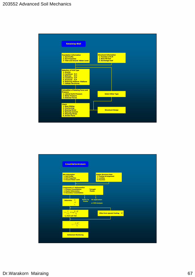
Structural Information 1. Function of R.M 2. Back filll Soil 3. Surchange load
Selection of R.W.Type 1. Gravity 2. Cantilever R/C 3. Battress R/C 4. Cantilever S/P 5. Anchored S/P 6. Relieving Platform Platform 7. Cellular Structures
Calcualtion of Relating Force andPressure 1. Lateral Earth Pressure 2. Water Pressure 3. External Forces
Check 1. Base Sliding 2. Overturning 3. Bearing Stress 4. Bearing moment 5. Shearing Stress 6. Anchor Force
Select Other Type
Structural Desige
Foundation Information 1. Soil Profile 2. Soil Properties 3. Tidal and Ground Water Level
Retaining Wall
Site Information 1. Soil Profile 2. Soil Properties 3. Ground Water Levle
Components of Settiemention 1. Primary Consolidation Terzaghi 2. Elastic Deformation Poulos 3. Secondary Consolidation
Supper Structure Data 1. Footing Arrangement 2. Loading 3. Function
Settlement Monitoring
Effect form ajacent Footing,
Elastic byPoulos
No Application
or FEM Analysis
ConsolidationAnalysis
i
vi T
HCt
2
=
0
0
0
log1 P
PPHe
CS c Δ+⋅⋅
+=
Cc from Lab Test
Determine
0
0
eP
PΔ
jPΔ
203552 Advanced Soil Mechanics
Dr.Warakorn Mairaing 68
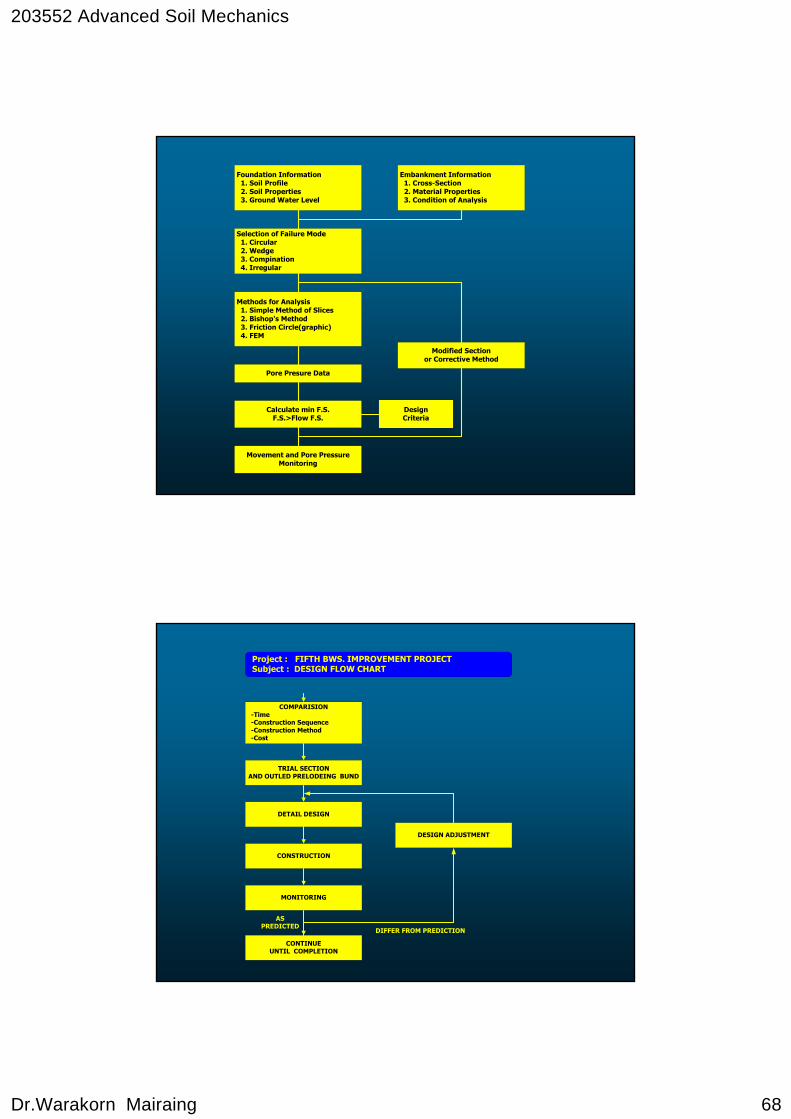
Foundation Information 1. Soil Profile 2. Soil Properties 3. Ground Water Level
Selection of Failure Mode 1. Circular 2. Wedge 3. Compination 4. Irregular
Methods for Analysis 1. Simple Method of Slices 2. Bishop's Method 3. Friction Circle(graphic) 4. FEM
Pore Presure Data
Calculate min F.S.F.S.>Flow F.S.
Movement and Pore PressureMonitoring
Embankment Information 1. Cross-Section 2. Material Properties 3. Condition of Analysis
Modified Sectionor Corrective Method
DesignCriteria
COMPARISION -Time -Construction Sequence -Construction Method -Cost
TRIAL SECTIONAND OUTLED PRELODEING BUND
DETAIL DESIGN
CONSTRUCTION
MONITORING
CONTINUEUNTIL COMPLETION
DESIGN ADJUSTMENT
Project : FIFTH BWS. IMPROVEMENT PROJECT Subject : DESIGN FLOW CHART
DIFFER FROM PREDICTION
ASPREDICTED
203552 Advanced Soil Mechanics
Dr.Warakorn Mairaing 69
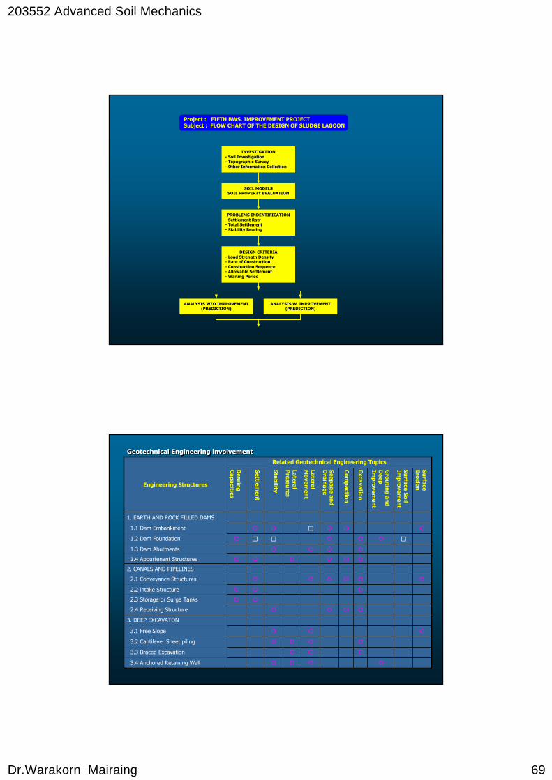
INVESTIGATION - Soil Investigation - Topographic Survey - Other Information Collrction
SOIL MODELSSOIL PROPERTY EVALUATION
PROBLEMS INDENTIFICATION - Settlement Ratr - Total Settlement - Stability Bearing
DESIGN CRITERIA - Load Strength Density - Rate of Construction - Construction Sequence - Allowable Settlement - Waiting Period
ANALYSIS W/O IMPROVEMENT(PREDICTION)
ANALYSIS W IMPROVEMENT(PREDICTION)
Project : FIFTH BWS. IMPROVEMENT PROJECT Subject : FLOW CHART OF THE DESIGN OF SLUDGE LAGOON
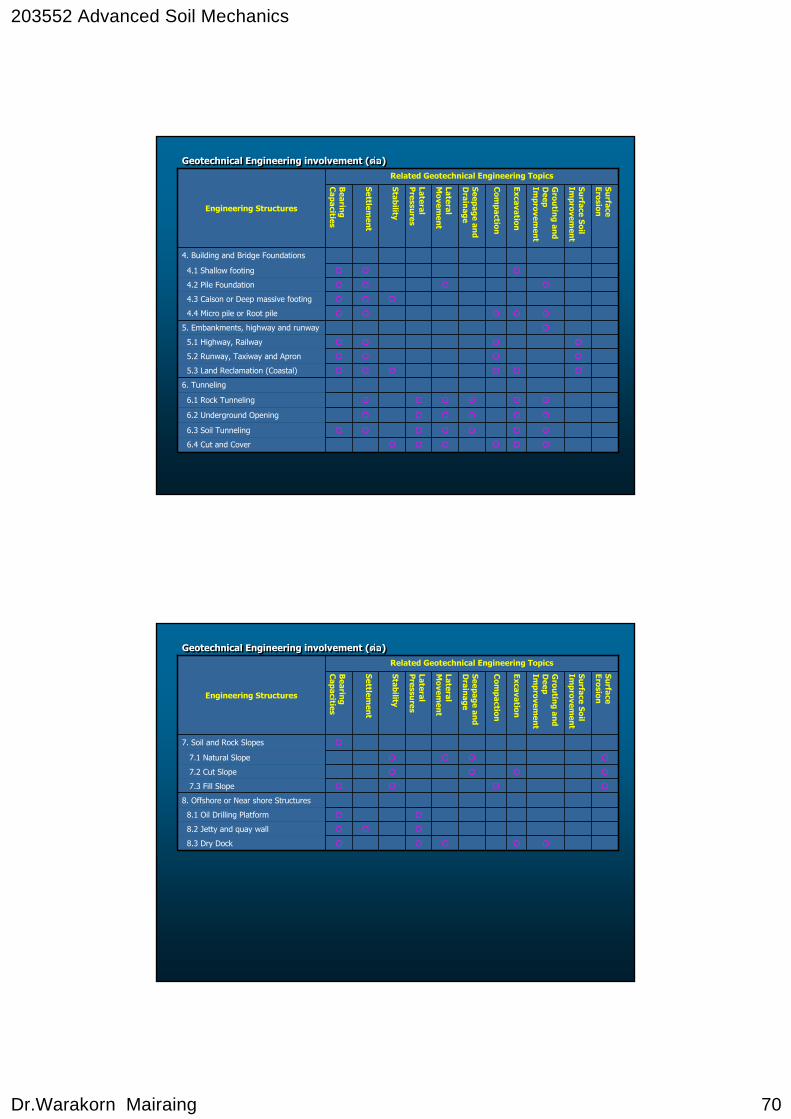
Geotechnical Engineering involvementGeotechnical Engineering involvement
3.1 Free Slope
3. DEEP EXCAVATON
3.2 Cantilever Sheet piling
3.3 Braced Excavation
2.2 intake Structure
2.1 Conveyance Structures
2.3 Storage or Surge Tanks
2.4 Receiving Structure
1.1 Dam Embankment
1.3 Dam Abutments
1.2 Dam Foundation
1.4 Appurtenant Structures
2. CANALS AND PIPELINES
Surface
Erosion
Surface Soil
Improvem
ent
Grou
ting and
Deep
Improvem
ent
Excavation
Com
paction
Seepage and
Drain
age
Lateral M
ovemen
t
Lateral P
ressures
Stability
Settlemen
t
Bearin
g C
apacities
3.4 Anchored Retaining Wall
1. EARTH AND ROCK FILLED DAMS
Related Geotechnical Engineering Topics
Engineering Structures
203552 Advanced Soil Mechanics
Dr.Warakorn Mairaing 70
Geotechnical Engineering involvement (ตอ)Geotechnical Engineering involvement (ตอ)
6.1 Rock Tunneling
6. Tunneling
6.2 Underground Opening
6.3 Soil Tunneling
5.2 Runway, Taxiway and Apron
5.1 Highway, Railway
5.3 Land Reclamation (Coastal)
4.1 Shallow footing
4.3 Caison or Deep massive footing
4.2 Pile Foundation
4.4 Micro pile or Root pile
5. Embankments, highway and runway
Surface
Erosion
Surface Soil
Improvem
ent
Grou
ting and
Deep
Improvem
ent
Excavation
Com
paction
Seepage and
Drain
age
Lateral M
ovemen
t
Lateral P
ressures
Stability
Settlemen
t
Bearin
g C
apacities
6.4 Cut and Cover
4. Building and Bridge Foundations
Related Geotechnical Engineering Topics
Engineering Structures
Geotechnical Engineering involvement (ตอ)Geotechnical Engineering involvement (ตอ)
8.2 Jetty and quay wall
8.1 Oil Drilling Platform
8.3 Dry Dock
7.1 Natural Slope
7.3 Fill Slope
7.2 Cut Slope
8. Offshore or Near shore Structures
Surface
Erosion
Surface Soil
Improvem
ent
Grou
ting and
Deep
Improvem
ent
Excavation
Com
paction
Seepage and
Drain
age
Lateral M
ovemen
t
Lateral P
ressures
Stability
Settlemen
t
Bearin
g C
apacities
7. Soil and Rock Slopes
Related Geotechnical Engineering Topics
Engineering Structures
203552 Advanced Soil Mechanics
Dr.Warakorn Mairaing 71
203552 Advanced Soil Mechanics
Dr.Warakorn Mairaing 72
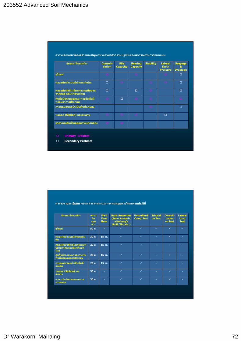
ตารางลกัษณะโครงสรางและปญหาทางดานวิศวกรรมปฐพท่ีีตองพิจารณาในการออกแบบ
อาคารบังคับนํ้าตลอดความยาวคลอง
ทอลอด (Siphon) และสะพาน
การขุดบอชลอนํ้าเปนพ้ืนที่แกมลิง
คันก้ันนํ้าภายนอกและภายในพื้นที่พรอมอาคารประกอบ
คลองผันนํ้าส่ีเหล่ียมคางหมูที่ขยายจากคลองเดิมหรือขุดใหม
คลองผันนํ้าแบบมีกําแพงกันดิน
อุโมงค
Seepage &
Drainage
Lateral Earth
Pressure
StabilityBearing Capacity
Pile Capacity
Consoli-dation
ลักษณะโครงสราง
Primary Problem
Secondary Problem
ตารางรายละเอยีดการเจาะสาํรวจทางและการทดสอบทางวศิวกรรมปฐพีท่ี
Basic Properties (Seive Analysis,
atterberg’sLimit, Wn, etc.)
---30 ม.อาคารบังคับน้ําตลอดความยาวคลอง
---30 ม.ทอลอด (Siphon) และสะพาน
---15 ม.20 ม.การขุดบอชลอน้ําเปนพื้นที่แกมลิง
--15 ม.20 ม.คันกั้นน้ําภายนอกและภายในพื้นที่พรอมอาคารประกอบ
---15 ม.20 ม.คลองผันน้ําส่ีเหล่ียมคางหมูที่ขยายจากคลองเดิมหรือขุดใหม
--15 ม.30 ม.คลองผันน้ําแบบมีกําแพงกันดิน
-50 ม.อุโมงค
Lateral Load Test
Consoli-dationon Test
Triaxialon Test
Unconfined Comp. Test
Field Vane Shear
ความลึกหลุมเจาะ
ลักษณะโครงสราง