lecture note : pramudiyanto, m.eng. -...
TRANSCRIPT

Session
Lecture note :Pramudiyanto, M.Eng.
g{x V|ä|Ä tÇw cÄtÇÇ|Çz XÇz|ÇxxÜ|Çz Xwâvtà|ÉÇ WxÑtÜàÅxÇàFaculty of Engineering, State University of Yogyakarta
Strength of Materials
Pure Bending
04
g{x V|ä|Ä tÇw cÄtÇÇ|Çz XÇz|ÇxxÜ|Çz Xwâvtà|ÉÇ WxÑtÜàÅxÇàFaculty of Engineering, State University of Yogyakarta
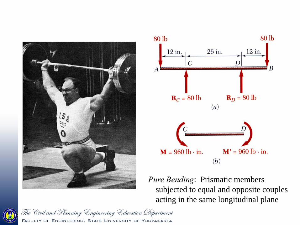
Pure Bending: Prismatic members subjected to equal and opposite couples acting in the same longitudinal plane
g{x V|ä|Ä tÇw cÄtÇÇ|Çz XÇz|ÇxxÜ|Çz Xwâvtà|ÉÇ WxÑtÜàÅxÇàFaculty of Engineering, State University of Yogyakarta
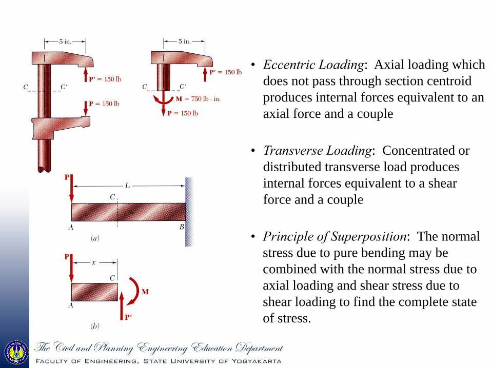
• Principle of Superposition: The normal stress due to pure bending may be combined with the normal stress due to axial loading and shear stress due to shear loading to find the complete state of stress.
• Eccentric Loading: Axial loading which does not pass through section centroid produces internal forces equivalent to an axial force and a couple
• Transverse Loading: Concentrated or distributed transverse load produces internal forces equivalent to a shear force and a couple

g{x V|ä|Ä tÇw cÄtÇÇ|Çz XÇz|ÇxxÜ|Çz Xwâvtà|ÉÇ WxÑtÜàÅxÇàFaculty of Engineering, State University of Yogyakarta
MdAyM
dAzMdAF
xz
xy
xx
00
• These requirements may be applied to the sums of the components and moments of the statically indeterminate elementary internal forces.
• Internal forces in any cross section are equivalent to a couple. The moment of the couple is the section bending moment.
• From statics, a couple M consists of two equal and opposite forces.
• The sum of the components of the forces in any direction is zero.
• The moment is the same about any axis perpendicular to the plane of the couple and zero about any axis contained in the plane.

g{x V|ä|Ä tÇw cÄtÇÇ|Çz XÇz|ÇxxÜ|Çz Xwâvtà|ÉÇ WxÑtÜàÅxÇàFaculty of Engineering, State University of Yogyakarta
Beam with a plane of symmetry in pure bending:
• member remains symmetric
• bends uniformly to form a circular arc
• cross-sectional plane passes through arc centerand remains planar
• length of top decreases and length of bottom increases
• a neutral surface must exist that is parallel to the upper and lower surfaces and for which the length does not change
• stresses and strains are negative (compressive) above the neutral plane and positive (tension) below it
g{x V|ä|Ä tÇw cÄtÇÇ|Çz XÇz|ÇxxÜ|Çz Xwâvtà|ÉÇ WxÑtÜàÅxÇàFaculty of Engineering, State University of Yogyakarta
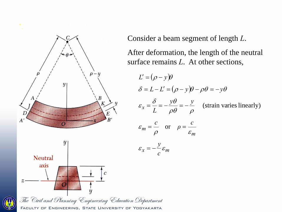
Consider a beam segment of length L.
After deformation, the length of the neutral surface remains L. At other sections,
mx
mm
x
cy
cρc
yyL
yyLL
yL
or
linearly) ries(strain va

g{x V|ä|Ä tÇw cÄtÇÇ|Çz XÇz|ÇxxÜ|Çz Xwâvtà|ÉÇ WxÑtÜàÅxÇàFaculty of Engineering, State University of Yogyakarta
• For a linearly elastic material,
linearly) varies(stressm
mxx
cy
EcyE
• For static equilibrium,
dAyc
dAcydAF
m
mxx
0
0
First moment with respect to neutral plane is zero. Therefore, the neutral surface must pass through the section centroid.
• For static equilibrium,
IMy
cy
SM
IMc
cIdAy
cM
dAcyydAyM
x
mx
m
mm
mx
ngSubstituti
2

g{x V|ä|Ä tÇw cÄtÇÇ|Çz XÇz|ÇxxÜ|Çz Xwâvtà|ÉÇ WxÑtÜàÅxÇàFaculty of Engineering, State University of Yogyakarta
• The maximum normal stress due to bending,
modulussection
inertia ofmoment section
cIS
ISM
IMc
m
A beam section with a larger section modulus will have a lower maximum stress
• Consider a rectangular beam cross section,
Ahbhhbh
cIS 6
1361
3121
2
Between two beams with the same cross sectional area, the beam with the greater depth will be more effective in resisting bending.
• Structural steel beams are designed to have a large section modulus.
g{x V|ä|Ä tÇw cÄtÇÇ|Çz XÇz|ÇxxÜ|Çz Xwâvtà|ÉÇ WxÑtÜàÅxÇàFaculty of Engineering, State University of Yogyakarta
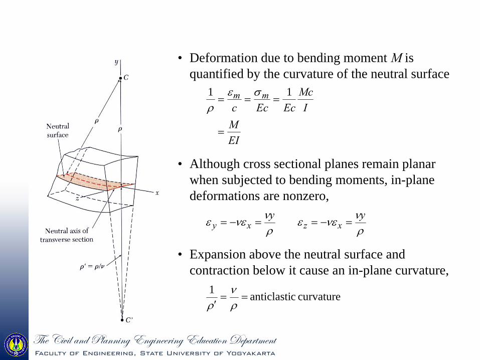
• Deformation due to bending moment M is quantified by the curvature of the neutral surface
EIM
IMc
EcEccmm
11
• Although cross sectional planes remain planar when subjected to bending moments, in-plane deformations are nonzero,
yy
xzxy
• Expansion above the neutral surface and contraction below it cause an in-plane curvature,
curvature canticlasti 1

g{x V|ä|Ä tÇw cÄtÇÇ|Çz XÇz|ÇxxÜ|Çz Xwâvtà|ÉÇ WxÑtÜàÅxÇàFaculty of Engineering, State University of Yogyakarta
A cast-iron machine part is acted upon by a 3 kN-m couple. Knowing E = 165 GPa and neglecting the effects of fillets, determine (a) the maximum tensile and compressive stresses, (b) the radius of curvature.
SOLUTION:
• Based on the cross section geometry, calculate the location of the section centroid and moment of inertia.
2dAIIAAyY x
• Apply the elastic flexural formula to find the maximum tensile and compressive stresses.
IMc
m
• Calculate the curvature
EIM
1

g{x V|ä|Ä tÇw cÄtÇÇ|Çz XÇz|ÇxxÜ|Çz Xwâvtà|ÉÇ WxÑtÜàÅxÇàFaculty of Engineering, State University of Yogyakarta
SOLUTION:
Based on the cross section geometry, calculate the location of the section centroid and moment of inertia.
mm 383000
10114 3
AAyY
3
3
3
32
101143000104220120030402109050180090201
mm ,mm ,mm Area,
AyA
Ayy
49-3
2312123
121
231212
m10868 mm10868
18120040301218002090
I
dAbhdAIIx

g{x V|ä|Ä tÇw cÄtÇÇ|Çz XÇz|ÇxxÜ|Çz Xwâvtà|ÉÇ WxÑtÜàÅxÇàFaculty of Engineering, State University of Yogyakarta
• Apply the elastic flexural formula to find the maximum tensile and compressive stresses.
49
49
mm10868m038.0mkN 3
mm10868m022.0mkN 3
IcM
IcM
IMc
BB
AA
m
MPa0.76A
MPa3.131B
• Calculate the curvature
49- m10868GPa 165mkN 3
1
EIM
m 7.47
m1095.201 1-3

g{x V|ä|Ä tÇw cÄtÇÇ|Çz XÇz|ÇxxÜ|Çz Xwâvtà|ÉÇ WxÑtÜàÅxÇàFaculty of Engineering, State University of Yogyakarta
BENDING OF A MEMBER MADE FROM SEVERAL MATERIAL
g{x V|ä|Ä tÇw cÄtÇÇ|Çz XÇz|ÇxxÜ|Çz Xwâvtà|ÉÇ WxÑtÜàÅxÇàFaculty of Engineering, State University of Yogyakarta
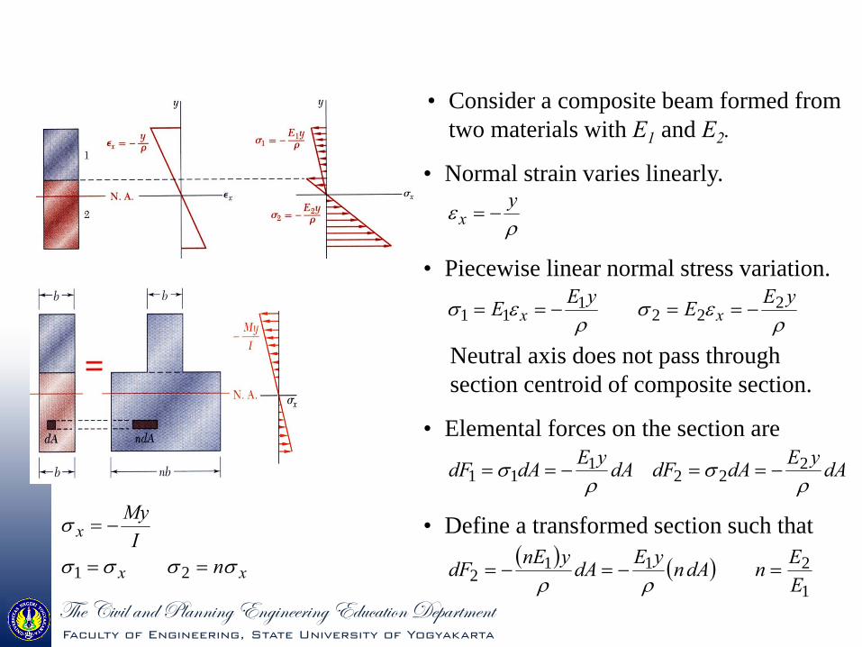
• Consider a composite beam formed from two materials with E1 and E2.
• Normal strain varies linearly.
y
x
• Piecewise linear normal stress variation.
yEEyEE xx
222
111
Neutral axis does not pass through section centroid of composite section.
• Elemental forces on the section are
dAyEdAdFdAyEdAdF
222
111
1
2112 E
EndAnyEdAynEdF
• Define a transformed section such that
xx
x
nI
My
21
g{x V|ä|Ä tÇw cÄtÇÇ|Çz XÇz|ÇxxÜ|Çz Xwâvtà|ÉÇ WxÑtÜàÅxÇàFaculty of Engineering, State University of Yogyakarta
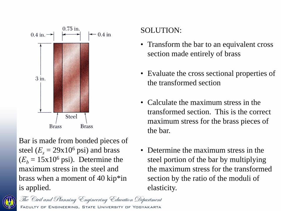
Bar is made from bonded pieces of steel (Es = 29x106 psi) and brass (Eb = 15x106 psi). Determine the maximum stress in the steel and brass when a moment of 40 kip*in is applied.
SOLUTION:
• Transform the bar to an equivalent cross section made entirely of brass
• Evaluate the cross sectional properties of the transformed section
• Calculate the maximum stress in the transformed section. This is the correct maximum stress for the brass pieces of the bar.
• Determine the maximum stress in the steel portion of the bar by multiplying the maximum stress for the transformed section by the ratio of the moduli of elasticity.

g{x V|ä|Ä tÇw cÄtÇÇ|Çz XÇz|ÇxxÜ|Çz Xwâvtà|ÉÇ WxÑtÜàÅxÇàFaculty of Engineering, State University of Yogyakarta
• Evaluate the transformed cross sectional properties
4
31213
121
in063.5
in 3in. 25.2
hbI T
SOLUTION:• Transform the bar to an equivalent cross section
made entirely of brass.
in 25.2in 4.0in 75.0933.1in 4.0
933.1psi1015psi1029
6
6
T
b
s
b
EEn
• Calculate the maximum stresses ksi 85.11
in 5.063in 5.1inkip 40
4
I
Mcm
ksi 85.11933.1max
max
ms
mb
n
ksi 22.9
ksi85.11
max
max
s
b

g{x V|ä|Ä tÇw cÄtÇÇ|Çz XÇz|ÇxxÜ|Çz Xwâvtà|ÉÇ WxÑtÜàÅxÇàFaculty of Engineering, State University of Yogyakarta
• Concrete beams subjected to bending moments are reinforced by steel rods.
• In the transformed section, the cross sectional area of the steel, As, is replaced by the equivalent areanAs where n = Es/Ec.
• To determine the location of the neutral axis,
0
022
21
dAnxAnxb
xdAnxbx
ss
s
• The normal stress in the concrete and steel
xsxc
x
nI
My
• The steel rods carry the entire tensile load below the neutral surface. The upper part of the concrete beam carries the compressive load.
g{x V|ä|Ä tÇw cÄtÇÇ|Çz XÇz|ÇxxÜ|Çz Xwâvtà|ÉÇ WxÑtÜàÅxÇàFaculty of Engineering, State University of Yogyakarta
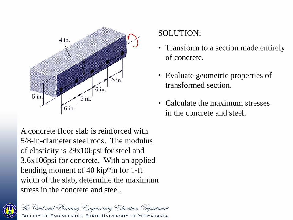
A concrete floor slab is reinforced with 5/8-in-diameter steel rods. The modulus of elasticity is 29x106psi for steel and 3.6x10⁶psi for concrete. With an applied bending moment of 40 kip*in for 1-ft width of the slab, determine the maximum stress in the concrete and steel.
SOLUTION:
• Transform to a section made entirely of concrete.
• Evaluate geometric properties of transformed section.
• Calculate the maximum stresses in the concrete and steel.

g{x V|ä|Ä tÇw cÄtÇÇ|Çz XÇz|ÇxxÜ|Çz Xwâvtà|ÉÇ WxÑtÜàÅxÇàFaculty of Engineering, State University of Yogyakarta
SOLUTION:• Transform to a section made entirely of concrete.
2285
4
6
6
in95.4in 206.8
06.8psi 106.3psi 1029
s
c
s
nA
EEn
• Evaluate the geometric properties of the transformed section.
422331 in4.44in55.2in95.4in45.1in12
in450.10495.42
12
I
xxxx
• Calculate the maximum stresses.
42
41
in44.4in55.2inkip4006.8
in44.4in1.45inkip40
IMcn
IMc
s
c
ksi306.1c
ksi52.18s

g{x V|ä|Ä tÇw cÄtÇÇ|Çz XÇz|ÇxxÜ|Çz Xwâvtà|ÉÇ WxÑtÜàÅxÇàFaculty of Engineering, State University of Yogyakarta
THANK YOU …That’s for now