led light engine / oled led linear / area module stark · pdf filesubject to change without...
TRANSCRIPT
www.tridonic.com 1Subject to change without notice.
Data sheet 09/16-LED209-8
LED light engine / OLED
LED linear / area
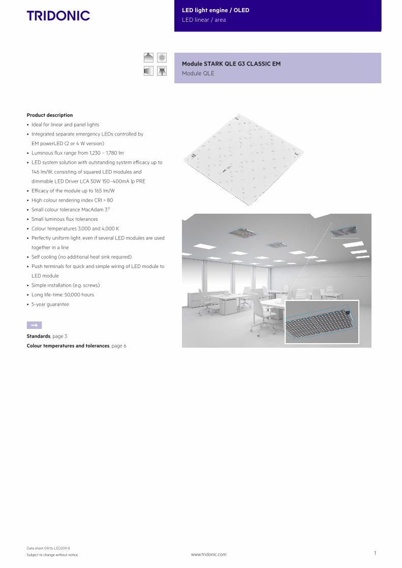
Product description
• Ideal for linear and panel lights
• Integrated separate emergency LEDs controlled by
EM powerLED (2 or 4 W version)
• Luminous flux range from 1,230 – 1,780 lm
• LED system solution with outstanding system efficacy up to
146 lm/W, consisting of squared LED modules and
dimmable LED Driver LCA 50W 150–400mA lp PRE
• Efficacy of the module up to 165 lm/W
• High colour rendering index CRI > 80
• Small colour tolerance MacAdam 31
• Small luminous flux tolerances
• Colour temperatures 3,000 and 4,000 K
• Perfectly uniform light, even if several LED modules are used
together in a line
• Self cooling (no additional heat sink required)
• Push terminals for quick and simple wiring of LED module to
LED module
• Simple installation (e.g. screws)
• Long life-time: 50,000 hours
• 5-year guarantee
ÈStandards, page 3
Colour temperatures and tolerances, page 6
Module STARK QLE G3 CLASSIC EM
Module QLE

www.tridonic.com 2Subject to change without notice.
Data sheet 09/16-LED209-8
LED light engine / OLED
LED linear / area
Specific technical dataType4 Photo-
metric code
Typ.luminous flux
at tp = 25 °C3
Typ.luminous flux
at tp = 45 °C3
Typ. forward current
Min. forward voltage at tp = 45 °C
Max. forward voltage at tp = 25 °C
Typ. power consumption at
tp = 45 °C3
Efficacy of the module at tp = 25 °C
Efficacy of the module at tp = 45 °C
Efficacy of the system at tp = 45 °C
Colour rendering index CRI
Operating mode HE at 250 mASTARK-QLE-G3-270-1250-830-CLA-EM 830/359 1,270 lm 1,230 lm 250 mA 27.3 V 33.0 V 7.8 W 160 lm/W 157 lm/W 141 lm/W > 80
STARK-QLE-G3-270-1250-840-CLA-EM 840/359 1,300 lm 1,270 lm 250 mA 27.3 V 33.0 V 7.8 W 165 lm/W 162 lm/W 146 lm/W > 80
Operating mode HO at 300 mASTARK-QLE-G3-270-1250-830-CLA-EM 830/359 1,490 lm 1,460 lm 300 mA 27.8 V 33.5 V 9.5 W 155 lm/W 152 lm/W 137 lm/W > 80
STARK-QLE-G3-270-1250-840-CLA-EM 840/359 1,530 lm 1,500 lm 300 mA 27.8 V 33.5 V 9.5 W 160 lm/W 157 lm/W 141 lm/W > 80
Operating mode HO at 350 mASTARK-QLE-G3-270-1250-830-CLA-EM 830/359 1,730 lm 1,670 lm 350 mA 28.3 V 34.0 V 11.3 W 151 lm/W 148 lm/W 133 lm/W > 80
STARK-QLE-G3-270-1250-840-CLA-EM 840/359 1,780 lm 1,730 lm 350 mA 28.3 V 34.0 V 11.3 W 156 lm/W 153 lm/W 138 lm/W > 80
Emergency mode – 350 mA (EM powerLED 2 W)STARK-QLE-G3-270-1250-830-CLA-EM 830/359 320 lm 310 lm 350 mA 4,9 V 6,3 V – – – – –
STARK-QLE-G3-270-1250-840-CLA-EM 840/359 330 lm 320 lm 350 mA 4,9 V 6,3 V – – – – –
Emergency mode – 700 mA (EM powerLED 4 W)STARK-QLE-G3-270-1250-830-CLA-EM 830/359 600 lm 590 lm 700 mA 5,6 V 7,1 V – – – – –
STARK-QLE-G3-270-1250-840-CLA-EM 840/359 620 lm 600 lm 700 mA 5,6 V 7,1 V – – – – –
1 Integral measurement over the complete module.
2 If mounted with M4 screws.
3 Tolerance range for optical data: ±7.5 % and electrical data: ±10 %.
4 HE ... high efficiency, HO ... high output.
Technical dataBeam characteristic 120°
Ambient temperature range -30 ... +65 °C
tp rated 45 °C
tc 85 °C
Max. DC forward current 900 mA
Max. permissible LF current ripple 990 mA
Max. permissible peak current 1,500 mA / max. 10 µs
Max. permissible output voltage of LED Driver2 500 V
Insulation test voltage 2 kV
ESD classification severity level 4
Risk group (EN 62471:2008) 1
Type of protection IP00
Module STARK QLE G3 CLASSIC EM
Module QLE
15.5270
222
270
180
Ø4,3
EM_Out(-)EM_In(+)
tp
QLE-G3-270
Ordering data
TypeArticle number
Colour temperature
Packaging carton
Weight per pc.
STARK-QLE-G3-270-1250-830-CLA-EM 28000389 3,000 K 40 pc(s). 0.140 kg
STARK-QLE-G3-270-1250-840-CLA-EM 28000390 4,000 K 40 pc(s). 0.140 kg

www.tridonic.com 3Subject to change without notice.
Data sheet 09/16-LED209-8
LED light engine / OLED
LED linear / area
1. Standards
IEC 62031IEC 62471IEC 61547IEC 55015IEC 61000-4-2
Type Forward current Energy classification
QLE-G3-270-1250-830-CLA-EM
250 mA A++
300 mA A++
350 mA A++
QLE-G3-270-1250-840-CLA-EM
250 mA A++
300 mA A++
350 mA A++
1.2 Energy classification
1st digit 2nd + 3rd digit 4th digit 5th digit 6th digit
Code CRIColour tempera-
ture in
Kelvin x 100
McAdam
initial
McAdam after
25% of the
life-time
(max.6000h)
Luminous flux after 25%
of the life-time (max.6000h)
Code Luminous flux
7 70 – 79 7 ≥ 70 %
8 80 – 89 8 ≥ 80 %
9 ≥90 9 ≥ 90 %
1.1 Photometric code
Key for photometric code, e. g. 830 / 449
2. Thermal details
2.1 tc point, ambient temperature and life-time
The temperature at tp reference point is crucial for the light output and life-time of a LED product.
For STARK QLE a tp temperature of 45 °C has to be complied in order to achieve an optimum between heat sink requirements, light output and life-time.
Compliance with the maximum permissible reference temperature at the tc point must be checked under operating conditions in a thermally stable state. The maximum value must be determined under worst-case conditions for the relevant application.
The tc and tp temperature of LED modules from Tridonic are measured at the same reference point.
2.3 Thermal design and heat sink
The rated life of LED products depends to a large extent on the temperature. If the permissible temperature limits are exceeded, the life of the STARK QLE will be greatly reduced or the STARK QLE may be destroyed.
2.2 Storage and humidityStorage temperature -40 ... +85 °C
Operation only in non condensing environment.Humidity during processing of the module should be between 0 to 70 %.
3. Installation / wiring
3.1 Electrical supply/choice of LED Driver
STARK QLE from Tridonic are not protected against overvoltages, overcur-rents, overloads or short-circuit currents. Safe and reliable operation can only be guaranteed in conjunction with a LED Driver which complies with the relevant standards. The use of LEDDriver from Tridonic in combination with STARK QLE guarantees the necessary protection for safe and reliable operation.
If a LED Driver other than from Tridonic is used, it must provide the following protection:• Short-circuit protection• Overload protection• Overtemperature protection
The STARK QLE must be supplied by a constant current LED Driver.Operation with a constant voltage LED Driver will lead to an irrevers-ible damage of the module.
Wrong polarity can damage the STARK QLE.
With parallel wiring tolerance-related differences in output are possible(thermal stress of the module) and can cause differences in brightness.If one module fails, the remaining modules may be overloaded.
STARK QLE can be operated either from SELV LED Drivers or from LED Drivers with LV output voltage.
STARK QLE are basic isolated up to 500 V against ground and can be mounted directly on earthed metal parts of the luminaire. If the max. output voltage of the LED Driver (also against earth) is above 500 V, an additional isolation between LED module and heat sink is required (for example by isolated thermal pads) or by a suitable luminaire construction.At voltages > 60 V an additional protection against direct touch (test finger) to the light emitting side of the module has to be guaranteed. This is typically achieved by means of a non removable light distributor over the module.
3.2 Wiring
Wiring examples
–+
UdriverLCAI 65W 150–400mA ECO lp
LN
–+–+–+–+
EM PowerLED 4WPermanent-line +
–
Akku
–+
in+
out–EM_in (+) EM_out (–)

www.tridonic.com 4Subject to change without notice.
Data sheet 09/16-LED209-8
LED light engine / OLED
LED linear / area
4.2 Lumen maintenance for STARK QLE
Forward
current
tp
temperatureL90 / F10 L90 / F50 L80 / F10 L80 / F50 L70 / F10 L70 / F50
250 mA45 °C 53,000 h >60,000 h >60,000 h >60,000 h >60,000 h >60,000 h
65 °C 26,000 h 39,000 h 55,000 h >60,000 h >60,000 h >60,000 h
300 mA45 °C 52,000 h >60,000 h >60,000 h >60,000 h >60,000 h >60,000 h
65 °C 26,000 h 38,000 h 54,000 h >60,000 h >60,000 h >60,000 h
350 mA45 °C 50,000 h >60,000 h >60,000 h >60,000 h >60,000 h >60,000 h
65 °C 25,000 h 37,000 h 52,000 h >60,000 h >60,000 h >60,000 h
3.5 EOS/ESD safety guidelines
The device / module contains components that are sensitive to electrostatic discharge and may only be installed in the factory and on site if appropriate EOS/ESD protection measures have been taken. No special measures need be taken for devices/modules with enclosed casings (contact with the pc board not possible), just nor-mal installation practice. Please note the requirements set out in the document EOS / ESD guidelines (Guideline_EOS_ESD.pdf) at: http://www.tridonic.com/esd-protection
Chemical substance may harm the LED module. Chemical reactions could lead to colour shift, reduced luminous flux or a total failure of the module caused by corrosion of electrical connections.
Materials which are used in LED applications (e.g. sealings, adhe-sives) must not produce dissolver gas. They must not be condensa-tion curing based, acetate curing based or contain sulfur, chlorine or phthalate.Avoid corrosive atmosphere during usage and storage.
3.4 Mounting instruction
None of the components of the STARK QLE (substrate, LED, electronic components etc.) may be exposed to tensile or compressive stresses.
Max. torque for fixing: 0.5 Nm.
The LED modules are mounted with 4 screws per module.In order not to damage the modules only rounded head screws and anadditional plastic flat washer should be used.
4.1 Life-time, lumen maintenance and failure rate
The light output of an LED Module decreases over the life-time, this is charac-terized with the L value.L70 means that the LED module will give 70 % of its initial luminous flux. This value is always related to the number of operation hours and therefore defines the life-time of an LED module.
As the L value is a statistical value and the lumen maintenace may vary over the delivered LED modules.The B value defines the amount of modules which are below the specific L value, e.g. L70B10 means 10 % of the LED modules are below 70 % of the inital luminous flux, respectivly 90 % will be above 70 % of the initial value. In addition the percentage of failed modules (fatal failure) is characterized by the C value.
The F value is the combination of the B and C value. That means for F degrada-tion and complete failures are considered, e.g. L70F10 means 10 % of the LED modules may fail or be below 70 % of the initial luminous flux.
4. Life-time3.3 Wiring type and cross section
The wiring can be in stranded wires with ferrules or solid with a cross section of 0.2 to 0.75 mm². For the push-wire connection you have to strip the insulation (8–9 mm).
8 – 9 mm
wire preparation:0.2 – 0.75 mm²
To remove the wires use a suitabel tool (e.g. Microcon release pin) or through twist and pull .

www.tridonic.com 5Subject to change without notice.
Data sheet 09/16-LED209-8
LED light engine / OLED
LED linear / area
The diagrams are based on statistic values.The real values can be different.
-2,20
-1,65
-1,10
1,10
-0,55
0,00
0,55
35 45 55 65tc [°C]
25 75 85
Rel.
forw
ard
volta
ge [V
]
30,5 31,030,0 31,5 32,0100
150
250
200
32,5 33,0
300
350
Forward voltage [V]
Forw
ard
curr
ent [
mA]
5,50 5,755,25 6,00 6,25100
200
400
300
6,50
500
600
700
Forward voltage EM [V]
Forw
ard
curr
ent E
M [m
A]
5. Electrical values
5.1 Typ. forward voltage vs. forward current
5.2 Forward voltage vs. tp temperature

www.tridonic.com 6Subject to change without notice.
Data sheet 09/16-LED209-8
LED light engine / OLED
LED linear / area
6.1 Coordinates and tolerances according to CIE 1931
The specified colour coordinates are measured integral by a current impulse of 250 mA and a duration of 100 ms.The ambient temperature of the measurement is ta = 25 °C.The measurement tolerance of the colour coordinates are ± 0.01.
3,000 K
x0 y0
Centre 0.4344 0.4032
380 420 460 500 540 580 620 660 700 740 7800
20
40
60
80
100
wave length [nm]
norm
. int
ensi
ty [%
]
380 420 460 500 540 580 620 660 700 740 7800
20
40
60
80
100
wave length [nm]
norm
. int
ensi
ty [%
]
0,3600
0,3650
0,3700
0,3750
0,3800
0,3850
0,3900
0,3950
0,4000
0,36
00
0,36
50
0,37
00
0,37
50
0,38
00
0,38
50
0,39
00
0,39
50
0,40
00
0,3850
0,3900
0,3950
0,4000
0,4050
0,4100
0,4150
0,4200
0,4250
0,41
50
0,42
00
0,42
50
0,43
00
0,43
50
0,44
00
0,44
50
0,45
00
0,45
50
4,000 K
x0 y0
Centre 0.3828 0.3803
MacAdam Ellipse: 3SDCM
MacAdam Ellipse: 3SDCM
6. Photometric charcteristics

www.tridonic.com 7Subject to change without notice.
Data sheet 09/16-LED209-8
LED light engine / OLED
LED linear / area
The optical design of the STARK QLE product line ensures optimumhomogenity for the light distribution.
0°
20
20
-20 40
40
60
60
80
100
80 100-40-60-80-100
10°-10°20°-20°
-30°
-40°
-50°
-60°
30°
40°
50°
60°
70°
80°
90°00
rela
tive
inte
nsity
Iv/Iv
, max
The colour temperature is measured integral over the complete module. The single LED light points can have deviations in the colour coordinates within MacAdam 7. To ensure an ideal mixture of colours and a homogenious light distri-bution a suitable optic (e. g. PMMA diffuser) and a sufficient spacing between module and optic (typ. 6 cm) should be used.
For further information see Design-in Guide, 3D data and photometric data on www.tridonic.com or on request.
6.2 Light distribution
6.3 Relative luminous flux vs. tc temperature
6.4 Relative luminous flux vs. operating current
70
80
90
110
100
35 45 55 6525 75 85tc [°C]
Rel.
light
out
put [
%]
50 100 1500 200 250 3000
25
50
75
100
350
125
150
Operating current [mA]
Rel.
lum
inou
s flu
x [%
]
100 200 3000 400 500 6000
25
50
75
700
100
Operating current EM [mA]
Rel.
lum
inou
s flu
x EM
[%]