led pedestrian hand / person / countdown modules ... · 1 led pedestrian hand / person / countdown...
TRANSCRIPT

1
LED Pedestrian Hand / Person / Countdown Modules Specification and Requirements Checklist
16” x 18”, 12” x 12” and 9” x 9” Modules October 20, 2008
Agency Name: Project: Date:
1 Overview 1.1 Purpose The purpose of this specification is to provide the minimum performance requirements for LED pedestrian signal modules (hereafter called module or modules) with “walking person”, “upraised hand”, and “countdown digit” icons. This specification includes the following sizes (nominal message bearing surface): 406mm x 457 mm (16 in x 18 in), 305mm x 305mm (12 in x 12 in), and 229mm x 229mm (9 in x 9 in ). This specification refers to definitions and practices described in Pedestrian Traffic Control Signal Indications (PTCSI) Part 2:Light Emitting Diode (LED) Pedestrian Traffic Signal Modules (PTCSI) Adopted March 19, 2004 and published in the Equipment and Materials Standards of the Institute of Transportation Engineers (ITE) and contains additional requirements to ensure optimum long term reliability and performance.
1.2 Manufacturers Requirements and Approvals
1.2.1 Manufacturers supplying products to this specification must be a registered participant and have the base part numbers being provided listed on the Intertek-ETL LED Traffic Signal Modules Certification Program approved products website. Countdown Only Modules do not require having the part number listed on the program website.
1.2.2 All LED Pedestrian Signal Modules shall be produced in a NAFTA participating country. 1.2.3 All 12 x 12 and 16 x 18 products shall be CSA approved.

2
2 Physical & Mechanical Requirements 2.1 General
2.1.1 Usage: Modules shall fit into pedestrian signal housings manufactured in accordance with the ITE PTCSI Standard without modification to the housing.
2.1.2 Installation requirements: Installation of a module into an existing pedestrian signal housing shall only require the removal of the existing optical unit components, i.e., lens, lamp module, gaskets, and reflector; shall be weather tight and fit securely in the housing; and shall connect directly to existing electrical wiring. Installation shall not require special tools.
2.1.3 The sizes of the message bearing surfaces shall be in accordance with the dimensions given in Table 1.
Table 1—Dimensions of Hand / Person Signal Sizes
Message BearingSurface
Height X Width
Minimum Message Size
Height X Width
229mm x 229mm(9" x 9")
152mm x 89mm(6" x 3.5")
305mm x 305mm(12" x 12")
297mm x 178mm(11" x 7")
406mm x 457mm(16" x 18")
297mm x 178mm(11" x 7")
2.1.4 All countdown display digits shall be 9 inches in height (225mm) to allow for use in all size crosswalks to comply with MUTCD recommendations. 2.2 The LED Signal Module
2.2.1 The module shall be capable of replacing the optical component of the pedestrian indication.
2.2.2 The lens shall have a textured outer surface to reduce glare.
2.2.3 The module lens may be a replaceable part, without the need to replace the complete module.
2.2.4 Icons that are printed on the lens shall be on the interior surfaces in order to prevent scratching and abrasion to the icons.
2.2.5 All icons and numbers shall have a uniform incandescent, non-pixilated appearance.
2.2.6 All LED utilized to illuminate the Hand and Person icons, shall be LED that have been manufactured utilizing material that have industry acceptance as being suitable for uses in outdoor applications. At no time is the use of LED that utilize AlGaAs technology acceptable.
3
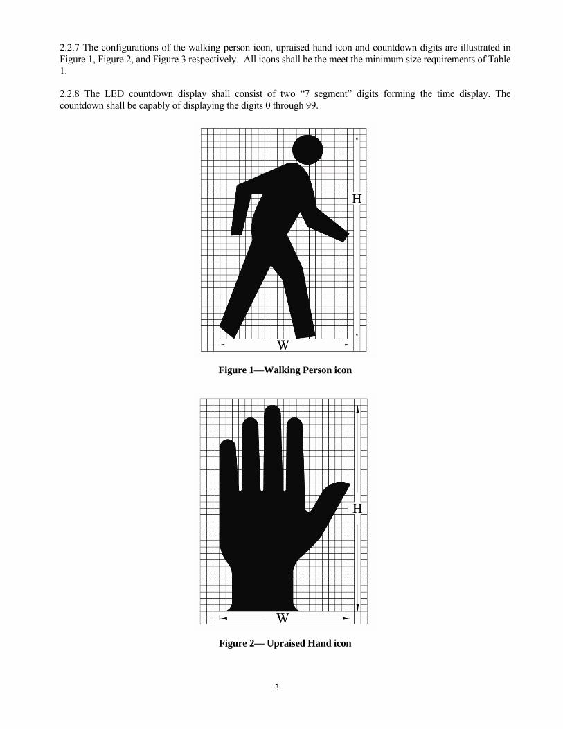
2.2.7 The configurations of the walking person icon, upraised hand icon and countdown digits are illustrated in Figure 1, Figure 2, and Figure 3 respectively. All icons shall be the meet the minimum size requirements of Table 1.
2.2.8 The LED countdown display shall consist of two “7 segment” digits forming the time display. The countdown shall be capably of displaying the digits 0 through 99.
Figure 1—Walking Person icon
Figure 2— Upraised Hand icon

4
Figure 3—Countdown Display
2.3 Environmental Requirements
2.3.1 All exposed components of a module shall be suitable for prolonged exposure to the environment, without appreciable degradation that would interfere with function or appearance. As a minimum, selected materials shall be rated for service for a period of a minimum of 60 months in a south-facing Arizona Desert installation.
2.3.2 A module shall be rated for use throughout an ambient operating temperature range, measured at the exposed rear of the module, of -40°C (-40°F) to +74°C (+165°F).
2.3.3 A module shall be protected against dust and moisture intrusion, including rain and blowing rain per Mil-STD-810F Method 506.4 Procedure 1.
2.4 Construction
2.4.1 The module shall be a single, self-contained device, not requiring on-site assembly for installation into an existing traffic signal housing.
2.4.2 The assembly and manufacturing process for the module shall be designed to assure all internal LED and electronic components are adequately supported to withstand mechanical shock and vibration from high winds and other sources.
2.5 Materials
2.5.1 Materials used for the lens and module construction shall conform to ASTM specifications for the materials, where applicable.
2.5.2 Enclosures containing either the power supply or electronic components of the signal module shall be made of UL94 flame retardant materials. The module lens is excluded from this requirement.

5
2.6 Module Identification
2.6.1 Each module shall be identified on the backside with the manufacturer’s name, model, operating characteristics and serial number. The operating characteristics identified shall include the nominal operating voltage and stabilized power consumption, in watts and Volt-Amperes. The main module label which includes the module’s serial number (or date code) and the model number shall be attached using polyester or vinyl self-adhesive labels. The use of paper labels is not acceptable.
2.6.2 Modules shall have a prominent and permanent vertical indexing indicator, i.e., UP Arrow, or the word UP or TOP, for correct indexing and orientation in the signal housing.
2.6.3 Modules conforming to all requirements of this specification shall have a statement on an attached label which states conformance to the latest version of the ITE PTCSI – Part 2 LED Pedestrian Signal Specification.
2.6.4 All modules must be labeled with the ETL Verified label shown in Figure 4. This label designates the compliance and listing with the Intertek-ETL Traffic Signal Certification Program.
3 Photometric Requirements 3.1 Luminance, Uniformity and Distribution
3.1.1 For a minimum period of 60 months, the minimum maintained luminance values for the modules under the operating conditions defined in Sections 2.3.2 and 4.2.1, when measured normal to the plane of the icon surface, shall not be less than:
• Walking Person: 2,200 cd/m2 • Upraised Hand: 1,400 cd/m2 • Countdown Digits: 1,400 cd/m2
3.1.1.1 The luminance of the emitting surface, measured at angles from the normal of the surface, may decrease linearly to a value of 50% of the values listed above at an angle of 15 degrees.
3.1.1.2 The light output requirements in this specification apply to pedestrian signal heads without any visors, hooded or louvered (egg-crate). Addition of such visors may affect the light output of the signal head.
3.1.2 The uniformity of the walking person, upraised hand, and countdown digit icons’ luminance shall meet a ratio of not more than 1 to 5 between the minimum and maximum luminance values, as measured in 12mm (0.5 in) diameter spots.
3.1.3. When operating within the temperature range specified in Section 2.4.2, the average luminance of the module shall not exceed three times the maintained minimum luminance of the modules, as defined in Section 3.1.1.
3.2 Chromaticity
3.2.1 The standard colors for the LED Pedestrian Signal Module shall be White for the walking person and Portland Orange for the upraised hand and countdown digit icons. The colors for these icons shall conform to the following color regions, based on the 1931 CIE chromaticity diagram:

6
Walking Person—White: Blue boundary: x = 0.280. 1st Green boundary: 0.280 ≤ x < 0.400 y = 0.7917•x + 0.0983. 2nd Green boundary: 0.400 ≤ x < 0.450 y = 0.4600•x + 0.2310. Yellow boundary: x = 0.450 1st Purple boundary: 0.450 ≤ x < 0.400 y = 0.4600•x + 0.1810. 2nd Purple boundary: 0.400 ≤ x < 0.280 y = 0.7917•x + 0.0483.
White
Point x y 1 0.280 0.320 2 0.400 0.415 3 0.450 0.438 4 0.450 0.388 5 0.400 0.365 6 0.280 0.270
Upraised Hand and Countdown Digits—Portland Orange: Yellow boundary: y = 0.390 White boundary: 0.600 ≤ x ≤ 0.680 y = 0.990 – x Red boundary: y = 0.331.
Portland Orange Point x y
1 0.6095 0.390 2 0.600 0.390 3 0.659 0.331 4 0.669 0.331
The color regions are illustrated in Attachment 1. 3.3. Color Uniformity
3.3.1 The uniformity of the emitted colors shall be such that any color measurement within a 12mm (0.5 in) spot on the emitting surface shall fall within the following regions around the average measured color of the entire emitting surface:
Walking Person—White: ( ) 04.022 ≤⎟⎠⎞⎜
⎝⎛Δ+Δ yx ;
where Δx and Δy are the differences in the chromaticity coordinates of the measured colors to the coordinates of the average color, using the CIE 1931 Chromaticity Diagram and a 2 degree Standard Observer.

7
Upraised Hand and Countdown Digits—Portland Orange:
The dominant wavelength for all individual color measurements shall be within ±3 nm of the dominant wavelength for the average of all the individual color measurements.
4 Electrical 4.1 General
4.1.1 All wiring shall meet the requirements of Section 13.02 of the VTCSH standard. Secured, color coded, 600V, 18 AWG jacketed wires, 1 meter (39 in) in length, conforming to the NFPA 70, National Electrical Code, and rated for service at +105°C, shall be provided.
4.1.2 The following color scheme shall be used for the module’s AC power leads: Orange for the upraised hand, Blue for the walking person, and White for common. A countdown only module shall contain and orange wire for connection to the hand, a blue wire for connection to the person, and a white wire for common connection.
4.1.3 For modules containing a Hand & Person Overlay display as well as a Countdown Timer display: Three wires (orange, blue, white) shall be provided for electrical connection. The countdown portion of the LED module shall be internally wired to the incoming Hand / Person power.
4.1.4 The AC power leads shall exit the module via a rubber grommetted strain relief, and shall be terminated with insulated female quick connect terminals with spade / tab adapters. The leads shall be separate at the point at which they leave the module.
4.1.4.1 All external wiring utilized in the modules shall be anti-capillary type wire to prevent the wicking of moisture to the interior of the module.
4.1.5 The Hand and Person Icons shall utilize separate power supplies. On countdown products, the countdown module must have its own power supply but may take the incoming AC power from the hand / person AC signal lines. All power supplies shall be located inside the signal module.
4.1.5.1 All power supplies shall be conformal coated for additional protection.
4.2 Voltage Range
4.2.1 LED signal modules shall operate from a 60±3 Hz AC line power over a voltage range from 80 to 135 VAC RMS. Nominal operating voltage for all measurements shall be 120 ± 3VAC RMS, unless otherwise specified.
4.2.2 Fluctuations in line voltage over the range of 80 to 135 VAC shall not affect luminous intensity by more than ±10 percent.
4.2.3 The module circuitry shall prevent flicker of the LED output at frequencies less than 100 Hz over the voltage range specified in Section 4.2.1.
4.2.4 Low Voltage Turn OFF: There shall be no visible illumination from the LED signal module when the applied voltage is less than 35 VAC.
4.2.5 Turn-ON and Turn-OFF Time: A module shall reach 90% of full illumination (turn-ON) within 75 msec of the application of the nominal operating voltage. The signal shall cease emitting visible illumination (turn-OFF) within 75 msec of the removal of the nominal operating voltage.
4.2.6 Default Condition: Applies to modules that have both the walking person and the hand as one module: For abnormal conditions when nominal voltage is applied to the unit across the two-phase wires or

8
simultaneously to both upraised hand and walking person icons, the pedestrian signal unit shall default to the upraised hand symbol. For units that contain a countdown module the countdown shall display a “0” then blank.
4.3 Transient Voltage Protection
4.3.1 The on-board circuitry of the module shall include voltage surge protection, to withstand high-repetition noise transients and low-repetition high-energy transients as stated in Section 2.1.8, NEMA Standard TS 2-2003.
4.4 Electronic Noise
4.4.1 The LED signal and associated on-board circuitry shall meet the requirements of the Federal Communication Commission (FCC) Title 47, Subpart B, Section 15 regulations concerning the emission of electronic noise by Class A digital devices.
4.5 Power Factor (PF), AC Harmonics. And Power
4.5.1 Modules shall provide a power factor of 0.90 or greater when operated at nominal operating voltage, and 25ºC (77ºF).
4.5.2 Total harmonic distortion induced into an AC power line by a module at nominal operating voltage, and at 25ºC (77ºF), Shall not Exceed 20%.
4.5.3Typical Power at 25ºC (77ºF) for the Pedestrian Signal Modules shall be the values shown in Table 2.
Table 2 -- Nominal Power of Pedestrian Signals
Wattage @ 25ºC Size Description Hand Person Countdown1
9x9 Person Only N/A 6 N/A 9x9 Hand Only 6 N/A N/A 12x12 Overlay H&P 8 6 N/A 12x12 Person Only N/A 7 N/A 12x12 Hand Only 8 N/A N/A 12x12 Countdown
Timer N/A N/A 5
16x18 Overlay H&P 8 6 N/A 16x18 Side by Side
H&P 8 7 N/A
16x18 H&P Overlay w/Countdown
9 7 5
1 Wattage shown is for the countdown module when the digit “18” is displayed

9
4.6 Controller Assembly Compatibility
4.6.1 The current draw for hand and person icons shall be sufficient to ensure compatibility and proper triggering and operation of load current switches and conflict monitors in signal controller units.
4.6.2 Off State Voltage Decay: When the hand or person icon is switched from the On state to the Off state the terminal voltage shall decay to a value less than 10 VAC RMS in less than 100 milliseconds when driven by a maximum allowed load switch leakage current of 10 milliamps peak (7.1 milliamps AC).
4.7 Countdown Drive Circuitry
4.7.1 The countdown portion of the signal shall have a high off-state input impedance so as not to provide a load indication to conflict monitors and interfere with the monitoring of the pedestrian signal. The input impedance of the countdown circuitry shall maintain a voltage reading above 25 VAC to the conflict monitor for up to four units connected on the same channel.
4.7.2 The Countdown Timer drive circuitry shall not be damaged when subjected to defective load switches providing a half wave signal input.
4.7.3 The countdown module shall be compatible with all traffic signal controllers that are fully compliant to NEMA TS-1, NEMA TS-2, Type 170, and Type 2070 traffic signal controller specifications.
4.7.4 The countdown module shall have an internal conflict monitor circuit preventing any possible conflicts between the Hand/Person signal indications and the Countdown Timer display. It shall be impossible for the display to countdown during a solid Hand indication.
4.8 Countdown Functionality
4.8.1 Per MUTCD Manual 2003 edition, with revisions 1 and 2 incorporated dated December 2007, section 4E.07: “Countdown displays should ONLY be used during the “Clearance Cycle”. They should NOT be used during the walk interval nor during the yellow change interval of a concurrent vehicular phase”.
4.8.2 The countdown timer module shall have a micro-processor capable of recording the pedestrian crossing timing when connected to a traffic controller. It shall be capable of displaying the digits 0 through 99.
4.8.3 When connected, the module shall blank out the display during the initial cycle while it records the countdown time using the Walk (Person) & D/Walk (Flashing Hand) signal indications. The hand and person icons shall be displayed as normal during this cycle.
4.8.4 The countdown timer module shall continuously monitor the traffic controller for any changes to the pedestrian phase time and re-program itself automatically if needed.
4.8.5 The countdown module shall register the time for the walk and clearance intervals individually and shall begin counting down at the beginning of the pedestrian clearance interval. The countdown module shall display the numerals in a continuous display and shall not flash during the countdown.
4.8.6 When the flashing Hand becomes solid, the module shall display 0 for one second and then blank-out. The display shall remain dark until the beginning of the next countdown.
4.8.7 In the event of a pre-emption sequence, the countdown module shall skip the pre-empted clearance time and reach “0” at the same time as the flashing Hand becomes solid and then remain dark until the next cycle.

10
4.8.8 In the cycle following a pre-emption call, the signal shall display the correct time and not be affected by the reduced previous cycle. The countdown shall remain synchronized with the signal indications and always reach 0 at the same time as the flashing Hand becomes solid.
4.8.9 The countdown timer shall be capable of displaying 2 consecutive complete Pedestrian Phases outputted by the traffic controller (no steady Hand signal between cycles). NOTE: When a controller is programmed with the option to serve a second consecutive pedestrian phase (walk followed by flashing don’t walk) if a pedestrian activates a pedestrian button during the clearance interval, and the controller is set to allow a second consecutive phase, the countdown will blank out during the walk, and restart counting down the correct time during the flashing don’t walk, just as in a regular PED phase.
4.8.10 The countdown module shall not display an erroneous or conflicting time when subjected to defective load switches. Should there be a short power interruption during the PED clearance interval or if voltage is applied to both the hand and person simultaneously the display will go to “0” then blank.
4.8.11 The countdown module shall have accessible dip-switches for the user selectable options. The unit shall have a removable plug on the rear allowing easy access to control the user selectable functions. The unit shall be shipped from the factory with the specified default setting.
4.8.11.1 Switch 1 – Blank Cycle Following a Timing Change – Factory default is “OFF”. When this switch is “OFF” the unit will allow the time to be displayed normally during the cycle following a truncated timing such as a preemption call. The countdown shall be capable of displaying the correct time and not affected by the previous reduced cycle. The unit will require 2 consecutive reduced cycles of identical value to validate and record a new time setting. If the timing is extended the unit will record it immediately. In the “ON” position when a change in timing is detected the unit will blank out during the following cycle while the new cycle time is measured and recorded if confirmed.
4.8.11.2 Switch 2 – Disables Auto-sync Mode- Factory default setting is “OFF”. When this switch is in the “OFF” position the auto-sync is enabled. When the clearance interval begins and the initial flash of the hand is not in sync with the walk signal the unit will measure the offset and reduce the duration of the first second by the value of the offset. This will ensure the countdown reached zero at the same time as the flashing hand becomes solid. In the “ON” position there is no time correction when the flashing hand is in offset with the walk signal. The duration of the first second will not be reduced and the hand will appear solid shortly before the countdown reaches zero.
4.8.11.3 Switch 3 – Countdown Starts with Flashing Hand Signal – Factory default setting is “ON”. When this switch is “ON” the countdown begins when the hand signal is turned on. With this switch “ON” and the auto-sync mode enabled a short power interruption will have no effect on the countdown display. With switch 3 in the “OFF” position the countdown begins when the walk signal is turned off. This eliminates the effect of an offset hand signal. When switch 3 is in the “OFF” position the auto-sync switch 2 has no effect on the countdown. In this mode if the power to the walk signal is interrupted, the unit will interpret this as the start of the clearance interval and will display the countdown time for 2 seconds before the operation is cancelled. The countdown will resume with the normal ending of the walk signal.
4.8.11.4 Switch 4 – Stores Time Value in Memory (Immediate. Restart) - Factory default setting is “OFF”. When this switch is in the “OFF” position and power is removed from the unit, the time value stored in the unit is erased. The unit will need to run a dark cycle before it can display the countdown again. In the “ON” position the countdown timing is stored in memory. Following a power interruption, the unit will restart with the stored value and not remain dark during the learning cycle. If the value is different after restart, it will be recorded and displayed correctly at the following cycle.
4.8.11.5 Switch 5 – All LEDs “ON” (Test Mode) – Factory default setting is “OFF”. With this switch in the “ON” position all LEDs are turned on simultaneously. With both switches 4 and 5 in the “ON” position the LED test mode will also scan the 7 individual segments of both digits.

11
4.8.11.6 The countdown shall be disabled when all switches are placed in the “ON” position.
5. Quality Assurance 5.1 General
5.1.1 Quality Assurance Program: Modules shall be manufactured in accordance with a vendor quality assurance (QA) program. The QA program shall include two types of quality assurance: (1) design quality assurance and (2) production quality assurance. The production quality assurance shall include statistically controlled routine tests to ensure minimum performance levels of modules built to meet this specification.
5.1.2 Record Keeping: QA process and test results documentation shall be kept on file for a minimum period of seven years.
5.1.3 Conformance: Module designs not satisfying design qualification testing and the production quality assurance testing performance requirements in Sections 5.3 and 5.4 should not be labeled, advertised, or sold as conforming to this specification.
5.1.4 Potential suppliers must complete and submit the LED Module Supplier checklist shown in Table 3 and provide a copy of the checklist with the submission of any proposals.
5.2 Manufacturers’ Serial Numbers
Each module shall be identified with the information specified in paragraph 2.6.
5.3 Production Tests & Inspections
5.3.1 Production Test Requirements: All modules shall undergo the following Production Testing & Inspection prior to shipment. Failure of a module to meet the requirements of Production Testing & Inspection shall be cause for rejection. Test results shall be maintained per the requirement of Section 5.1.2.
5.3.1.1 All Production Tests shall be performed at an ambient temperature of 25ºC (77ºF) and at the nominal operating voltage of 120 VAC.
5.3.2 Production Luminance Test: Hand/Person/Digit icons shall be tested for maintained minimum luminance. Any measurement with a correlation to the luminance requirements of Section 3.1.1 may be used. Modules that do not meet the maintained minimum luminance requirements as per Section 3.1.1 shall be rejected.
5.3.3 Power Factor: Hand/Person icons shall be tested for power factor per the requirements of Section 4.5.1. A commercially available power factor meter may be used to perform this measurement. Failure of a module to meet the requirements for power factor (4.5.1) shall be cause for rejection of the module.
5.3.4 Current Consumption Measurement: Hand/Person icons shall be measured for current flow in Amperes. The measured current values shall be compared against the design current values from design qualification measurements in Section 5.4.5.1. A measured current consumption in excess of 120% of the design qualification current value for an ambient temperature of 25ºC (77ºF) shall be cause for rejection of the module.
5.3.5 Visual Inspection: All modules shall be visually inspected for any exterior physical damage or assembly anomalies. Careful attention shall be paid to the surface of the lens to ensure there are no scratches (abrasions), cracks, chips, discoloration, or other defects. The presence of any such defects shall be cause for rejection of the module.

12
5.4 Design Qualification Testing
5.4.1 Design Qualification testing shall be performed on the hand/person icons of new module designs, and when a major design change has been implemented on existing hand/person pedestrian signal designs. Modules used in design qualification testing shall be representative of the manufacturer’s proposed normal production.
5.4.1.1 Testing shall be performed once every 5 years or when the module design or LED technology has been changed. Test data shall be retained by the module manufacturer in accordance with Section 5.1.2 or for 60 months following final production of a specific design, whichever is longer.
5.4.1.2 Six modules shall be used in Design Qualification Testing. All six modules shall be subjected to conditioning (5.4.2), followed by the Environmental Tests (5.4.3). Following the Environmental Tests, three modules shall undergo Photometric & Colorimetric Tests (5.4.4). The remaining three modules shall undergo the Electrical Tests (5.4.5) and Controller Compatibility Tests (5.4.5.11). Tests shall be conducted in the order described herein, unless otherwise specified.
5.4.1.3 In order for a module design to be considered acceptable for marking with the label described in 2.7.1, all tested modules must comply with the acceptance/rejection criteria for the Environmental Tests (5.4.3), Photometric & Colorimetric Tests (5.4.4), Electrical Tests (5.4.5), and Controller Assembly Compatibility Tests (5.4.5.11).
5.4.2 Conditioning: Modules shall be energized for a minimum of 24 hours, at 100% duty cycle, in an ambient temperature of +60°C (+140°F).
5.4.3 Environmental Testing:
5.4.3.1 Mechanical Vibration Testing: Three modules shall be tested per MIL-STD-883, Test Method 2007, using three 4-minute cycles along each x, y, and z axis, at a force of 2.5 Gs, with a frequency sweep from 2 Hz to 120 Hz.
5.4.3.2 Temperature Cycling. Temperature cycling shall be performed per MIL-STD-883, Test method 1010. The temperature range shall be per Section 2.5.2. A minimum of 20 cycles shall be performed with a 30-minute transfer time between temperature extremes and a 30-minute dwell time at each temperature. Modules under test shall be non-operating.
5.4.3.3 Moisture Resistance. Moisture resistance testing shall be performed on a sample of three modules per MIL-STD-810F, Procedure I, Rain and Blowing Rain. The test shall be conduced on a stand-alone unit, without a protective housing. The rainfall rate shall be 1.7 mm/min (4 in/hr) and droplet size shall predominantly be between 0.5 mm and 4.5 mm. The module shall be rotated through 120 degrees and the duration of the test shall be 30 minutes. The module shall be energized throughout the test. The water shall be at 25°C. The wind velocity shall be 80 km/hr (50 mph). Any evidence of internal moisture into the module shall be cause for rejection.
5.4.3.4 UV Stabilization: Documentation may be provided that clearly demonstrates that the external lens complies with the requirements of section 2.5.1.
5.4.3.5. Environmental Tests Evaluation: At the conclusion of the Environmental Tests, all the modules will be visually inspected for damage.
5.4.3.6 Acceptance/Rejection Criteria: The loosening of the lens, or any internal components, or evidence of other physical damage, such as cracking of the module lens or housing, presence of internal moisture after testing, a change in haze of >15%,of if the module extinguished itself shall be considered a failure for the proposed design.

13
5.4.4 Photometric & Colorimetric Tests: Three of the modules that were subjected to the Environmental Tests shall undergo Photometric & Colorimetric Tests. Unless otherwise specified, these tests shall be performed with the modules energized at nominal operating voltage (120 VAC).
5.4.4.1 Maintained Minimum Luminance: The sample set shall be tested for maintained minimum luminance at both 25°C and 74°C. Prior to making measurements, each module shall be operated at a 100% duty cycle for a minimum of 60 minutes at the test temperature.
5.4.4.2 For elevated temperature testing at 74°C, the modules to be tested shall be mounted in a temperature-testing chamber so that the external surface of the emitting lens is outside the chamber and all portions behind the lens are within the chamber at a temperature of 74ºC (165ºF). The air temperature in front of the lens of the module shall be maintained at a minimum of 49°C (120°F) during the elevated temperature testing.
5.4.4.2.1 Measurements shall be made using a luminance meter located on the physical axis of the module lens at a distance such that the selected aperture samples a spot size of 12mm (0.5 inch) at the lens surface. The position of the luminance meter shall be translated from side to side and up and down, so as to sample nine points across the emitting surface of the module.
5.4.4.2.2 The luminance values for the nine points shall be recorded and the average value calculated.
5.4.4.2.3 Modules for which the calculated average value of luminance does not meet the requirements of Section 3.1.1 shall be rejected.
5.4.4.3 Luminance Uniformity: The sample set shall be tested in accordance with the requirements of Section 3.1.2, using the recorded values of luminance, at a testing temperature of 25°C. The highest and lowest values of luminance shall be recorded and compared. Modules not meeting requirements of Section 3.1.2 shall be rejected.
5.4.4.3.1 Maximum Luminance: The sample set shall be tested in accordance with the requirements of Section 3.1.3, using the recorded values of luminance, at testing temperatures of 25°C and 74°C. Modules for which the calculated average value of the luminance exceeds the limit established in Section 3.1.3, at either or both temperature levels, shall be rejected.
5.4.4.4 Chromaticity: From the sample set, two modules shall be measured for chromaticity per the requirements of Section 3.2. Prior to making measurements, each module shall be operated at a 100% duty cycle for a minimum of 60 minutes at +25°C (+77°F). Color measurements shall be made using a spectro-radiometer with a maximum bandwidth of 4 nm, or a colorimeter that has a measurement uncertainty of less than 2.5% over the emission bandwidth of the icon under measurement.
5.4.4.4.1 Measurements shall be made by locating the instrument on the axis normal to the emitting surface of the icon, at a distance such that the meter samples a spot size of 12mm (0.5 inch) at the lens surface. The position of the instrument shall be translated from side to side and up and down, so as to sample nine points across the emitting surface of the module.
5.4.4.4.2 The chromaticity coordinates of the emitted light at the nine points shall be recorded and the average value calculated. In addition, the dominant wavelengths for the nine sampled points of the hand icon shall be calculated and recorded.
5.4.4.4.3 Modules for which the calculated average chromaticity coordinates do not meet the requirements of Section 3.2 shall be rejected.

14
5.4.4.4.4 Color Uniformity: The sample set shall be tested in accordance with the requirements of Section 3.3, using the recorded values of the chromaticity coordinates (walking person—white icon) or the dominant wavelengths (hand—portland orange icon), from Section 5.4.4.4. Modules not meeting requirements of Section 3.3 shall be rejected.
5.4.4.5 Photometric & Colorimetric Tests Evaluation: At the conclusion of the Photometric & Colorimetric Tests, the measurement data shall be compared to the requirements of Sections 3.1, 3.2 and 3.3.
5.4.4.6 Acceptance/Rejection Criteria: The failure of any module to meet all of the requirements for maintained minimum luminance (3.1.1) and maximum permissible luminance (3.1.3) at 25°C and/or 74°C, and the requirements for luminance uniformity (3.1.2), chromaticity (3.2), and color uniformity (3.3) at 25°C, shall be considered a failure of the proposed design.
5.4.5 Electrical.
5.4.5.1 Current Consumption: The sample set shall be measured for current flow in Amperes. The measured current values shall be used for quality comparison of Production Quality Assurance current measurements on production modules.
5.4.5.2 Temperature vs. Power Consumption: The sample set shall be tested to measure the change in power consumption in Watts versus the change in temperature over the specified operating temperature range. This data shall be recorded and may be made available to all end users.
5.4.5.3 Power Consumption vs. Long-Term Life: If the rated power consumption of the module at 25°C (77ºF) and 74ºC (165ºF) will change more than 10% over time, the manufacturer may provide documentation showing the projected power consumption in Watts of the module over a period of 60 months from the date of installation. This documentation may include data for the following temperature points: 0°C (32ºF), 25°C (77ºF), 50ºC (122ºF) and 74ºC (165ºF).
5.4.5.4 Power Factor (PF): The sample set shall be measured for power factor per the requirements of Section 4.5.1. A commercially available power factor meter may be used to perform this measurement. The PF shall be calculated separately for each of the icons for the module.
5.4.5.5 Total Harmonic Distortion (THD): The sample set shall be measured for total harmonic distortion per the requirements of Section 4.5.2. A commercially available total harmonic distortion meter may be used to perform this measurement. The THD shall be measured for each of the icons for the module.
5.4.5.6 Low Voltage Turn Off: The sample set shall be measured to ensure compliance with the low voltage turn-off requirement of Section 4.2.4. To test for this condition each icon must first be fully illuminated at the nominal operating voltage. The applied voltage shall then be reduced to the point where there is no visible illumination. This point must be greater than 35 VAC RMS AC.
5.4.5.7 Turn-On and Turn-Off Times: The sample set shall be measured to ensure compliance with the turn-on and turn-off requirements of Section 4.2.5. The measurement shall be conducted using a two channel oscilloscope to measure the time delay between when the module is energized at 120 VAC RMS and when the light output reaches 90% of full output. A photo-multiplier tube shall be used to measure the light output of the module. The same apparatus shall be used to measure the time delay between when the module is de-energized and when the light output reaches 0% of full output. The time in msec shall be plotted in the X axis and light output shall be plotted in the Y axis.
5.4.5.7.1 A module not reaching 90% nominal light output within 75 msec at start-up or still showing light output 75 msec after being de-energized shall be deemed to have failed this test.

15
5.4.5.8 Electronic Noise: From the sample set, a sample of 2 modules shall be tested. The modules shall be tested for conformance with the requirements of a Class A digital device, as specified in FCC Title 47, Subpart B, Section 15.109(b).
5.4.5.9 Nondestructive Transient Immunity: The sample set shall be tested for transient immunity using the procedure described in Section 2.1.8, NEMA Standard TS 2-2003. Failure to meet these requirements shall be cause for rejection.
5.4.5.10 Electrical Tests Evaluation: At the conclusion of the Electrical Tests, the measurement data shall be compared to the requirements of Sections 4.2 through 4.5.
5.4.5.10.1 Acceptance/Rejection Criteria: The failure of any module to meet the applicable requirements of Sections 4.2 through 4.5 shall be considered a failure of the proposed design.
5.4.5.11 Controller Assembly Compatibility: Due to the low load current draw and high off-state impedance of modules, testing shall be performed to ensure the module design is compatible and operates properly with load current switches and conflict monitors in NEMA and Type 170 traffic signal control units.
Before performing the following tests, the manufacturer should ascertain which type of signal controller unit(s) the procuring traffic authority customer has in use and tailor these tests to meet the requirements of that type and model of controller unit(s).
5.4.5.11.1 Load Switch Compatibility: The sample set shall be tested for compatibility and proper operation with load current switches. Each module shall be connected to a variable ac voltage supply. The ac line current into the module shall be monitored for sufficient current draw to ensure proper load switch operation while the voltage is varied from 80 VAC RMS to 135 VAC RMS. Failure of the current draw to ensure proper load current switch operation shall be cause for rejection.
5.4.5.11.2 Signal Conflict Monitor (MMU) Compatibility: The sample set shall be tested for compatibility and proper operation with signal conflict monitors. Each module shall be operated from a 135 VAC RMS supply. A 19.5 kΩ resistor shall be wired in series in the hot line between the module and the ac power supply. A single-pole-single-throw switch shall be wired in parallel across the 19.5 kΩ resistor. A 220 kΩ shunt resistor shall be wired between the hot line connection and the neutral line connection on the module. Conflict monitor compatibility shall be tested by measuring the voltage decay across the 220 kΩ shunt resistor as follows: The single-pole-single-throw switch shall be closed, shorting out the 19.5 kΩ resistor, allowing the ac power supply to illuminate the module. Next the switch shall be opened, and the voltage across the 220 kΩ shunt resistor shall be measured for a decay to a value equal to or less than 10 VAC RMS within a time period equal to or less than 100 milliseconds. This test shall be repeated a sufficient number of times to ensure that testing occurs at the peak of the ac line voltage cycle.
A voltage decay across the 220 kΩ shunt resistor to a value greater than 10 VAC RMS or a decay time to 10 VAC RMS greater then 100 milliseconds shall be cause for rejection.
5.4.5.11.3 Controller Assembly Compatibility Evaluation: At the conclusion of the Controller Assembly Compatibility Tests, the measurement data shall be compared to the requirements of the specific make and model Controller Assembly with which the module design is intended to operate.
5.4.5.11.4 Acceptance/Rejection Criteria: Failure of the module to draw sufficient current to ensure compatibility with the load current switches in the appropriate Controller Assembly (4.6.1) and/or failure of the circuit voltage to decay to a value equal to or less than 10VAC RMS within a time period equal to or less than 100 milliseconds (4.6.2) shall be considered a failure of the proposed design.

16
6.0 Warranty Requirements 6.1 Warranty 6.1.1 Manufacturers shall provide a written warranty issued by the factory located in the NAFTA country of module origin with the following minimum provisions: 6.1.2 Modules shall, at the manufacturer’s option, be repaired or replaced if the module fails to function as intended due to workmanship or material defects within the first 60 months from the date of delivery. 6.1.3 Modules shall, at the manufacturer’s option, be repaired or replaced if the module exhibit luminous intensities less than the minimum specified values within the first 60 months of the date of delivery. 6.1.4 Upon request, the LED lamp module manufacturer shall provide written documentation of its ability to satisfy a worst-case, catastrophic warranty claim. 6.1.4.1 A current corporate annual report duly-certified by an independent auditing firm, containing financial statements illustrating sufficient cash-on-hand and net worth to satisfy a worst-case, catastrophic warranty claim is an example of suitable documentation. 6.1.4.2 The documentation shall clearly disclose: a) The country in which the factory of module origin is located. b) The name of the company or organization that owns the factory of module origin including any and all of its parent companies and/or organizations, and their respective country of corporate citizenship. 6.1.4.3 For firms with business and/or corporate citizenship in the United States of less than seven years, the process by which the end-users/owners of the modules will be able to obtain worst-case, catastrophic warranty service in the event of bankruptcy or cessation-of-operations by the firm supplying the modules within North America, or in the event of bankruptcy or cessation-of-operations by the owner of the factory of origin, shall be clearly disclosed.
Figure 4. Intertek- ETL Verified Label

17
ATTACHMENT 1
Color Regions for Pedestrian Traffic Control Signal Indications(1931 CIE Chromticity Diagram)
0.00
0.10
0.20
0.30
0.40
0.50
0.60
0.70
0.80
0.90
0.00 0.10 0.20 0.30 0.40 0.50 0.60 0.70 0.80
x
y
490
500
510
White:1) x = 0.2802) y = 0.7917*x + 0.09833) y = 0.4600*x + 0.23104) x = 0.4505) y = 0.4600*x + 0.18106) y = 0.7917*x + 0.0483
1
2
34
5
6
1
23
Portland Orange:1) y = 0.3902) y = 0.990 - x3) y = 0.331

18
Table 3. LED Module Supplier Checklist
Below checklist must be completed and provided with this submission. Substantiation data must be submitted in either book form or electronic (disc) format. In all cases the substantiation data being submitted must be indexed and tabulated referencing the appropriate article number.
Vendor / Manufacturer Information:
Distributor Name:
Address:
City:
State:
Contact Name:
Contact Phone No. LED Module Manufacturer:
Name:
Address:
City:
State:
Contact Name:
Contact Phone No. LED Module Manufacturing Location:
Address:
City:
State:
Country:

19
LED Module Manufacturer’s Part Numbers:
9 x 9 12 x 12 16 x 18
Hand (H) N/A
Person (P) N/A
H / P Side by Side N/A N/A
H/P Overlay N/A
H/P Overlay w/ Countdown
N/A N/A
Countdown N/A N/A
Section Requirements Per ITE PTCSI Part 2 LED Pedestrian Signal Modules,
March 19, 2004 With Countdown if required
and Additional Requirements Specified by this Document
Comply
Y / N2
Substantiation Requirements
1.2 Manufacturers Requirements 1.2.1 Manufacture participates in Intertek-ETL LED Traffic Signal
Module Certification program and proposed base products, excluding countdown only modules, are listed on the ETL website for the program.
Provide letter of participation from ETL and copy of web page from ETL web site showing product listing.
1.2.2 All Modules produced in NAFTA participating country. Provide Statement of Country of Origin on Manufacturer’s letterhead.
1.2.3 All 12 x 12 and 16 x 18 Modules shall be CSA approved. Provide copy of CSA approval certificate.
2. Physical & Mechanical Requirements – Summary 2.1.1 Stand-alone units shall fit into PTCSI approved Pedestrian signal
housings without modification to the housing.
2.1.2 Installation of LED modules shall not require special tooling and shall connect directly to the exiting electrical wiring system.
2.1.3 Message bearing surface complies with sizes listed in Table 1. 2.1.4 All countdown digits shall be a minimum of 9 inches tall.
2.2.1 LED module shall be capable of replacing existing optical components of the conventional signal head.
2.2.2 Lens Outer surface textured to reduce glare. 2.2.4 Printed icons shall be on the inner surface of the lens. 2.2.5 All icons shall have a uniform incandescent appearance. 2.2.6 The LEDS shall be suitable for outdoor applications and not be
AlGaAs Technology. Provide a copy of the Data Sheet
for the LEDs utilized in the Traffic Module.
2.2.7 All icons comply with minimum sizes listed in Table 1. 2.2.8 Countdown, if specified consists of two “7 segment” digits capable
of displaying 0 through 99.

20
Section Requirements Per ITE PTCSI Part 2 LED Pedestrian Signal Modules,
March 19, 2004 With Countdown if required
and Additional Requirements Specified by this Document
Comply
Y / N2
Substantiation Requirements
2.3.1 All exposed components shall be suitable for prolonged exposure to the environment without interfering to the function or appearance for a period of at least 60 months (in a south-facing Arizona desert).
Provide letter of compliance for materials supplier.
2.3.2 All modules shall be rated for use throughout an ambient operating temperature range, measured at the exposed rear of the module, of -40°C to + 74°C.
Intertek ETL test lab results Report # _______________
Date of Report ______________
Page # ___________________
2.3.3 A module shall be protected against dust and moisture intrusion, including rain and blowing rain, MIL-STD-810F, test method 506.4, procedure 1, Rain and Blowing Rain.
Intertek ETL test lab results Report # _______________
Date of Report ______________
Page # ___________________
2.4.1 A module shall be self-contained, not requiring on-site assembly. 2.4.2 Assembly and manufacturing processes for a module shall be
designed that all internal LED and electronic components withstand mechanical shock and vibration due to high wind and other sources. MIL-STD-883 Method 2007 under ITE 6.4.3.1 Test methodology.
Intertek ETL test lab results Report # _______________
Date of Report ______________
Page # ___________________
2.5.1 Materials used for the lens and module construction shall conform to ASTM specifications for the materials, where applicable.
2.5.2 LED module enclosure that contains the power supply shall be made of UL94 flame retardant materials.
2.6.1 Each module shall be identified with manufacturer's name, model, operating characteristics (nominal voltage and stabilized power consumption) and serial number.
Provide sample label showing required marking.
2.6.2 Modules must be clearly marked “with an UP arrow or the word UP or TOP for correct indexing.
Provide drawing or photo showing designations.
2.6.3 Modules shall state conformance to latest ITE PTCSI – Part 2 Pedestrian Signal specification.
Provide sample label showing required marking.
2.6.4 Modules to be labeled with Intertek-ETL verified label. Provide drawing of label to be used.
3. Photometric Requirements - Summary
3.1.1 Minimum Maintained Luminous - intensity must be maintained over the temperature range of -40°C to +74°C over the voltage range of 80 to 135 V AC for a minimum period of 60 months, in accordance with ITE PTCSI. The MMLI for the countdown digit shall be 1400 cd/m2.
Intertek ETL test lab results Report # _______________
Date of Report ______________
Page # ___________________
3.1.2 Module shall meet an intensity uniformity ratio of not more than 5 to 1.
Intertek ETL test lab results Report # _______________
Date of Report ______________
Page # ___________________

21
Section Requirements Per ITE PTCSI Part 2 LED Pedestrian Signal Modules,
March 19, 2004 With Countdown if required
and Additional Requirements Specified by this Document
Comply
Y / N2
Substantiation Requirements
3.1.3 Maximum permissible luminous intensity shall not exceed three times the required peak value of the minimum maintained luminous intensity for the selected Icon.
Intertek ETL test lab results Report # _______________
Date of Report ______________
Page # ___________________
3.2.1 Color regions: the measured chromaticity coordinates of modules shall conform to the requirements of 3.2. using White for the walking person and Portland Orange for the upraised hand / countdown.
Intertek ETL test lab results Report # _______________
Date of Report ______________
Page # ___________________
3.3 Color Uniformity: The dominant wavelength for the Portland Orange color measurement of a portion of the emitting surface of a module shall be within + or - 3 nm of the dominant wavelength for the average color measurement of the emitting surface as a whole. For the walking person the uniformity shall be calculated utilizing the formula provides in paragraph 3.3.
Intertek ETL test lab results Report # _______________
Date of Report ______________
Page # ___________________
4. Electrical Requirements – Summary 4.1.1 General: Wire consist of two secured, color coded, 600 V, jacketed
wires, a minimum length of 39", 20 AWG, 105°C rated, conforming to NFPA 70.
Provide wire specification.
4.1.2 Wire color shall be blue for walking person, orange for the hand and white for the AC common.
4.1.3 Units with a hand / person overlay and countdown timer shall have the countdown timer internally wired in the module to the appropriate incoming power from the Hand and Person Icons.
4.1.4 AC wires shall enter the housing vie a rubber grommetted strain relief, and shall be terminated with insulated female quick connect terminals with spade / tab adapters.
4.1.4.1 All external wiring shall be anti-capillary type wire. Provide wire specification. 4.1.5 Hand / Person Icons shall utilize separate power supplies.
Countdown module must have separate power supply but may take power from the incoming Hand/ Person power wires. All power supplies shall be located internal to the module.
4.1.5.1 All power supplies shall be located internal to the module and be conformal coated.
4.2.1 Voltage range of 80 to 135 VAC RMS, operate off a 60±3 Hz AC line.
Intertek ETL test lab results Report # _______________
Date of Report ______________
Page # ___________________
4.2.2 Fluctuations over the voltage range of 80 to 135 VAC shall not affect the luminous intensity by more than + or – 10.
Intertek ETL test lab results Report # _______________
Date of Report ______________
Page # ___________________
4.2.3 The module shall prevent flicker of the LED output at frequencies less then 100 Hz over the voltage range of 80 to 135 V AC RMS.

22
Section Requirements Per ITE PTCSI Part 2 LED Pedestrian Signal Modules,
March 19, 2004 With Countdown if required
and Additional Requirements Specified by this Document
Comply
Y / N2
Substantiation Requirements
4.2.4 Low voltage turn OFF: there shall be no visible illumination from the LED signal module when the applied voltage is less than 35 V AC.
Intertek ETL test lab results Report # _______________
Date of Report ______________
Page # ___________________
4.2.5 Turn ON time: A module shall reach 90 % of full illumination within 75 msec of the application of the nominal operating voltage, Turn OFF time: The signal shall cease emitting visible illumination within 75 msec of the removal of the nominal operating voltage.
Intertek ETL test lab results Report # _______________
Date of Report ______________
Page # ___________________
4.2.6 For abnormal conditions when nominal voltage is applied to the phase wires of the hand / person icons, the display will default to the hand signal, the countdown under this condition will display 0 then blank.
4.3.1 Transient Voltage Protection: LED module shall withstand NEMA standard TS-2-2003, section 2.1.8.
Intertek ETL test lab results Report # _______________
Date of Report ______________
Page # ___________________
4.4.1 Emission of Electronic noise shall meet FCC Title 47, Subpart B, section 15 for class A digital device.
Intertek ETL test lab results Report # _______________
Date of Report ______________
Page # ___________________
4.5.1 Power Factor of .90 or greater at nominal voltage and 25°C. Intertek ETL test lab results Report # _______________
Date of Report ______________
Page # ___________________
4.5.2 THD shall not exceed 20% at 25°C. Intertek ETL test lab results Report # _______________
Date of Report ______________
Page # ___________________
4.5.3 Typical Power at 25°C shall meet the requirements shown in Table 2.
Intertek ETL test lab results Report # _______________
Date of Report ______________
Page # ___________________
4.6.1 Sufficient current draw to ensure compatibility and proper triggering and operation of the load switches and conflict monitors in signal controller units.
Intertek ETL test lab results Report # _______________
Date of Report ______________
Page # ___________________

23
Section Requirements Per ITE PTCSI Part 2 LED Pedestrian Signal Modules,
March 19, 2004 With Countdown if required
and Additional Requirements Specified by this Document
Comply
Y / N2
Substantiation Requirements
4.6.2 Off state Voltage Decay: Voltage shall decay to less than 10 VAC RMS in less than 100 ms when switched from On to OFF state if maximum load switch leakage current is 10 mA peak.
Intertek ETL test lab results Report # _______________
Date of Report ______________
Page # ___________________
4.7 Countdown Drive Circuitry (when required) 4.7.1 Countdown timer shall have high off-state impedance to allow for 4
units to be connected to the same channel.
4.7.2 Countdown shall not be damaged when exposed to defective Load switch providing a half wave input.
4.7.3 Countdown shall be compatible with NEMA TS-1, TS-2, Type 170 and Type 2070 signal controllers.
4.7.4 Countdown shall have an internal conflict monitor making it impossible to display a countdown during a solid hand indication.
4.8 Countdown Functionality (when required). 4.8.1 Countdown only displays during the Pedestrian Clearance Interval.
4.8.2 Countdown shall have microprocessor capable of recording the pedestrian crossing timing when connected to traffic controller.
4.8.3 Countdown shall be blank during first cycle after connection while recording time required for countdown.
4.8.4 Countdown monitors controller for changes and reprograms automatically if needed.
4.8.5 Countdown begins count at start of the pedestrian clearance interval.
4.8.6 When flashing hand becomes solid countdown displays “0” for 1 second when hand becomes solid then goes blank.
4.8.7 Upon pre-emption the countdown skips the clearance time and reaches “0” at the same time the hand becomes solid.
4.8.8 Countdown returns to normal operation after pre-emption.
4.8.9 Countdown shall be capable of timing 2 consecutive complete pedestrian cycles (no hand signal) outputted by the traffic controller.
4.8.10 Countdown shall not display erroneous time when connected to a defective load switch.
4.8.11 Countdown shall have user accessible dip switches via a removable plug on rear that shall allow easy access.
4.8.11.2 Sw.1 Blank Cycle Following a Timing Change – Default setting is OFF.
Provide Module Manufacturer’s Instruction Sheet.
4.8.11.2 Sw. 2 Disables Auto Sync mode – Default setting is OFF. Provide Module Manufacturer’s Instruction Sheet.
4.8.11.3 Sw. 3 Countdown Starts with Flashing Hand Signal – Default setting is ON.
Provide Module Manufacturer’s Instruction Sheet.
4.8.11.4 Sw. 4 Stores Time Value in Memory (Immediate Restart) – Default setting is OFF.
Provide Module Manufacturer’s Instruction Sheet.
4.8.11.5 Sw. 5 All LEDs On (Test Mode) – Default setting is OFF. Provide Module Manufacturer’s Instruction Sheet.

24
Section Requirements Per ITE PTCSI Part 2 LED Pedestrian Signal Modules,
March 19, 2004 With Countdown if required
and Additional Requirements Specified by this Document
Comply
Y / N2
Substantiation Requirements
4.8.11.6 The Countdown shall be disabled when all switches are in the “ON” position.
Provide Module Manufacturer’s Instruction Sheet.
5.0 Quality Assurance 5.1.2 Vendor Records maintained for 7 years.
5.2 Modules identified with information required per section 2.6. Provide Samples or drawing of the labels.
5.3 All modules are tested and inspected per the production test requirements of section 5.3.
5.4 Intertek ETL Test Report must be supplied for all products demonstrating compliance to the design qualification requirements of section 5.4 of this document and section 6.4 of the ITE PTCSI LED Pedestrian Traffic Signal Module Adopted March 19, 2004.
Intertek-ETL test reports Report # ___________________
Date of Report ______________ 6.0 Warranty Requirements 6.1.1 Manufacturer shall issue a written warranty statement, stating
compliance to the warranty requirements of this document. Attach Manufacturer’s Warranty
Statement. 6.1.2 Module to be repaired or replaced if the module fails to function as a
result of workmanship or material defects within 60 months of date of delivery.
Attach Manufacturer’s Warranty Statement.
6.1.3 Modules that fail to comply with the minimum intensity requirements within the first 60 months shall at the manufacturer’s option, be repaired or replaced.
Attach Manufacturer’s Warranty Statement.
2 For all sections above where non-compliance is indicated, please provide a detailed explanation on a separate sheet.