lee tunnel job sheet - bachy soletanche€¦ · lee tunnel project diaphragm walls london, u.k....
TRANSCRIPT
Lee Tunnel Project
Diaphragm Walls
London, U.K.
Scope of Works: Beckton Overflow Shaft: 1500mm thick diaphragm wall shaft 89m deep approximately 23m internal diameter pre liner wall. 79m deep excavation. Beckton Connection Shaft: 1500mm thick diaphragm wall shaft 92m deep approximately 28m internal diameter pre liner wall. 81m deep excavation Tideway Pumping Shaft: 1800mm thick diaphragm wall shaft 98m deep approximately 40m internal diameter pre liner wall. 82.5m deep excavation Abbey Mills Station Shaft: F 1200mm thick diaphragm wall shaft 84m deep approximately 28m internal diameter pre liner wall. 72m deep excavation. Ab-Abbey Mills Station Shaft:G 1500mm thick diaphragm wall shaft 86m deep approximately 28m internal diameter pre liner wall. 72m deep excavation. Beckton Overflow Shaft Grouting Works: Curtain Grouting - 83nr holes to 11m depth below the dia-phragm wall through reservation tubes Break Out Grout Block - 16m x 8m x 16m block, compromising of 148 boreholes at 1.5m c/c to a depth of 76m. In total 71276m3 C50/60 concrete and 5143 tonnes of rein-forcement steel installed including glass fibre in TBM portals.
INTRODUCTION:
The Thames Tideway Tunnels programme is a key component
of the upgrade of London’s combined sewer system. The first
section to be constructed is the Lee Tunnel between the
Beckton Sewage Treatment Works and the Abbey Mills
Pumping Station.
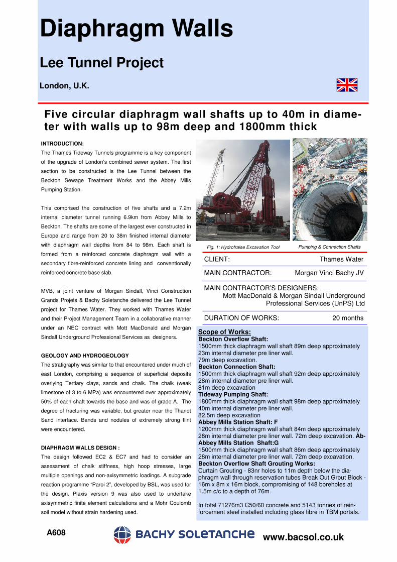
This comprised the construction of five shafts and a 7.2m
internal diameter tunnel running 6.9km from Abbey Mills to
Beckton. The shafts are some of the largest ever constructed in
Europe and range from 20 to 38m finished internal diameter
with diaphragm wall depths from 84 to 98m. Each shaft is
formed from a reinforced concrete diaphragm wall with a
secondary fibre-reinforced concrete lining and conventionally
reinforced concrete base slab.
MVB, a joint venture of Morgan Sindall, Vinci Construction
Grands Projets & Bachy Soletanche delivered the Lee Tunnel
project for Thames Water. They worked with Thames Water
and their Project Management Team in a collaborative manner
under an NEC contract with Mott MacDonald and Morgan
Sindall Underground Professional Services as designers.
GEOLOGY AND HYDROGEOLOGY
The stratigraphy was similar to that encountered under much of
east London, comprising a sequence of superficial deposits
overlying Tertiary clays, sands and chalk. The chalk (weak
limestone of 3 to 6 MPa) was encountered over approximately
50% of each shaft towards the base and was of grade A. The
degree of fracturing was variable, but greater near the Thanet
Sand interface. Bands and nodules of extremely strong flint
were encountered.
DIAPHRAGM WALLS DESIGN :
The design followed EC2 & EC7 and had to consider an
assessment of chalk stiffness, high hoop stresses, large
multiple openings and non-axisymmetric loadings. A subgrade
reaction programme “Paroi 2”, developed by BSL, was used for
the design. Plaxis version 9 was also used to undertake
axisymmetric finite element calculations and a Mohr Coulomb
soil model without strain hardening used.
A608
Five circular diaphragm wall shafts up to 40m in diame-ter with walls up to 98m deep and 1800mm thick
CLIENT: Thames Water
MAIN CONTRACTOR: Morgan Vinci Bachy JV
MAIN CONTRACTOR’S DESIGNERS: Mott MacDonald & Morgan Sindall Underground
Professional Services (UnPS) Ltd
www.bacsol.co.uk
DURATION OF WORKS: 20 months
Fig. 1: Hydrofraise Excavation Tool Pumping & Connection Shafts
A608
Diaphragm Wall Panel Excavation:
The diaphragm wall panels were
excavated using the Hydrofraise unit
(reverse circulation milling machine) as a
series of overlapping rectangular panels
forming a faceted circle. Primary panels
were up to 7.2m wide comprising 3 “bites”.
Secondary single bite panels overlapped
and cut into the concrete of the primaries.
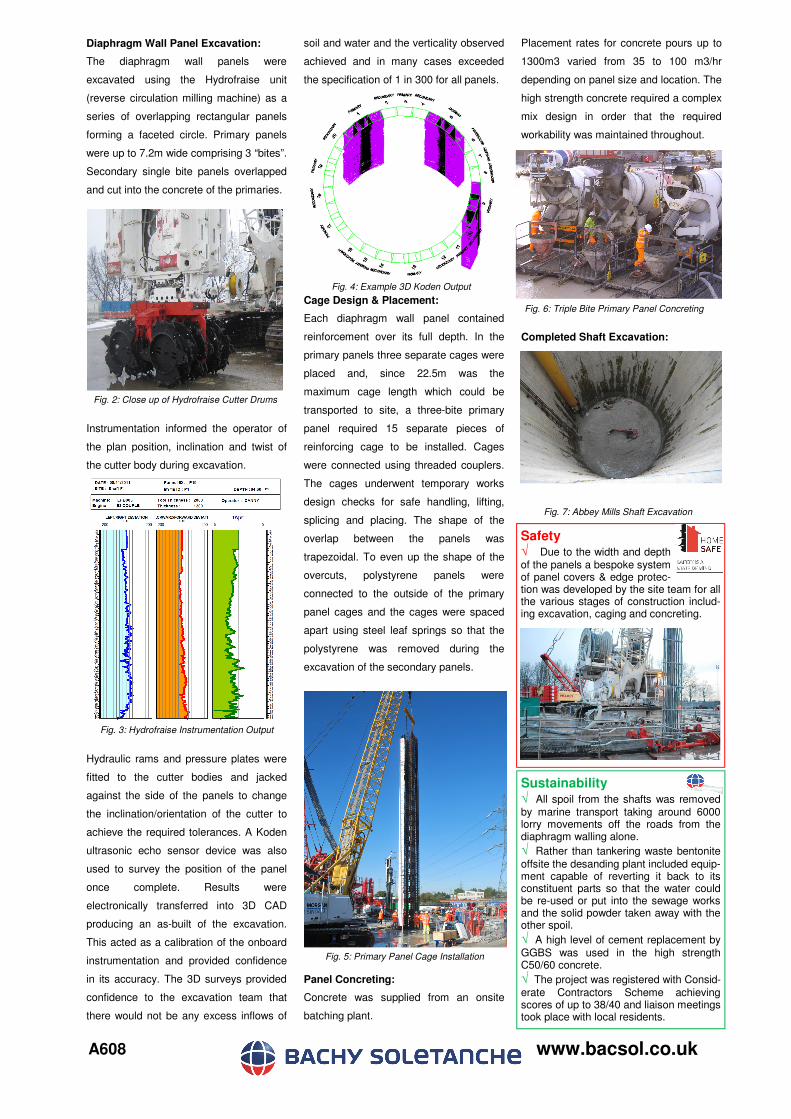
Instrumentation informed the operator of
the plan position, inclination and twist of
the cutter body during excavation.
Hydraulic rams and pressure plates were
fitted to the cutter bodies and jacked
against the side of the panels to change
the inclination/orientation of the cutter to
achieve the required tolerances. A Koden
ultrasonic echo sensor device was also
used to survey the position of the panel
once complete. Results were
electronically transferred into 3D CAD
producing an as-built of the excavation.
This acted as a calibration of the onboard
instrumentation and provided confidence
in its accuracy. The 3D surveys provided
confidence to the excavation team that
there would not be any excess inflows of
soil and water and the verticality observed
achieved and in many cases exceeded
the specification of 1 in 300 for all panels.
Cage Design & Placement:
Each diaphragm wall panel contained
reinforcement over its full depth. In the
primary panels three separate cages were
placed and, since 22.5m was the
maximum cage length which could be
transported to site, a three-bite primary
panel required 15 separate pieces of
reinforcing cage to be installed. Cages
were connected using threaded couplers.
The cages underwent temporary works
design checks for safe handling, lifting,
splicing and placing. The shape of the
overlap between the panels was
trapezoidal. To even up the shape of the
overcuts, polystyrene panels were
connected to the outside of the primary
panel cages and the cages were spaced
apart using steel leaf springs so that the
polystyrene was removed during the
excavation of the secondary panels.
Panel Concreting:
Concrete was supplied from an onsite
batching plant.
Placement rates for concrete pours up to
1300m3 varied from 35 to 100 m3/hr
depending on panel size and location. The
high strength concrete required a complex
mix design in order that the required
workability was maintained throughout.
Completed Shaft Excavation:
www.bacsol.co.uk
Sustainability √ All spoil from the shafts was removed by marine transport taking around 6000 lorry movements off the roads from the diaphragm walling alone. √ Rather than tankering waste bentonite
offsite the desanding plant included equip-ment capable of reverting it back to its constituent parts so that the water could be re-used or put into the sewage works and the solid powder taken away with the other spoil.
√ A high level of cement replacement by
GGBS was used in the high strength C50/60 concrete.
√ The project was registered with Consid-
erate Contractors Scheme achieving scores of up to 38/40 and liaison meetings took place with local residents.
Fig. 3: Hydrofraise Instrumentation Output
Safety √ Due to the width and depth of the panels a bespoke system of panel covers & edge protec-tion was developed by the site team for all the various stages of construction includ-ing excavation, caging and concreting.
Fig. 2: Close up of Hydrofraise Cutter Drums
Fig. 4: Example 3D Koden Output
Fig. 5: Primary Panel Cage Installation
Fig. 6: Triple Bite Primary Panel Concreting
Fig. 7: Abbey Mills Shaft Excavation