lego mindstorms ev3 -...
TRANSCRIPT
Using Sensors

Using the Infrared SensorINDEX
Home
General
ToolsProgramming BlocksData Logging
Getting StartedProgramsProject PropertiesConnecting to EV3Hardware PagePort SelectionData WiresData TypesContent EditorTeacher ModeManaging FilesEV3 Keyboard ShortcutsSupported TextDaisy ChainingPrinting
Using SensorsInfrared (IR)IR Beacon ModeIR Proximity ModeIR Remote ModeUltrasonicColorTimerTouchBrick ButtonsMotor RotationGyroNXT SoundTemperatureEnergy Meter
The Infrared Sensor can detect infrared light signals that are sentfrom the Remote Infrared Beacon (IR Beacon). The Infrared Sensorcan also send its own infrared light signal, and detect the reflectionof this light by other objects.
The Infrared Sensor can be used in three different modes:Proximity, Beacon, and Remote.
PROXIMITY MODE
In Proximity mode, the Infrared Sensor sends its own infraredsignal and can detect the reflection of this signal by an object infront of the sensor. The strength of the reflected signal can be usedto estimate the proximity of (distance to) the object.
See Using the Infrared Sensor Proximity Mode.
BEACON MODE
In Beacon mode, the IR Beacon transmits a special beacon signalcontinuously, and the Infrared Sensor can detect the approximateposition of the beacon in front of the sensor.
See Using the Infrared Sensor Beacon Mode.
Infrared (IR)
Quick linksProximity ModeBeacon ModeRemote Mode

Infrared light is the same kind of signal used by most TV remotecontrols. You cannot see infrared light, but, like visible light, it isblocked if objects are in the way. The IR Beacon must have a“line of sight” to the Infrared Sensor to be seen. Sunlight can alsointerfere with the infrared signals, although normal room lightshould not affect it.
REMOTE MODE
In Remote mode, the Infrared Sensor can detect button presses onthe IR Beacon. You can use the Remote mode to make a remotecontrol for your robot, for example.
See Using the Infrared Sensor Remote Mode.
Tips and Tricks

Using the Infrared Sensor BeaconMode
INDEX
Home
General
ToolsProgramming BlocksData Logging
Getting StartedProgramsProject PropertiesConnecting to EV3Hardware PagePort SelectionData WiresData TypesContent EditorTeacher ModeManaging FilesEV3 Keyboard ShortcutsSupported TextDaisy ChainingPrinting
Using SensorsInfrared (IR)IR Beacon ModeIR Proximity ModeIR Remote ModeUltrasonicColorTimerTouchBrick ButtonsMotor RotationGyroNXT SoundTemperatureEnergy Meter
Infrared Sensor
Remote Infrared Beacon
In Beacon mode, the Infrared Sensor can detect the approximate position of theRemote Infrared Beacon (IR Beacon) in front of the sensor. The sensor can giveyou the beacon’s Proximity (relative distance from the sensor) and its Heading(angle from the direction the sensor is pointing). You could use the Beacon mode,for example, to make your robot seek out and drive toward the IR Beacon.
TURN ON THE BEACON AND CHOOSE A CHANNEL
Turn the beacon on by pressing the Beacon Mode button on the top of the IRBeacon. The LED Indicator will turn on and stay on. The beacon will stay on andtransmit continuously until you press the Beacon Mode button again to turn it off.
Choose one of the four channels from the Channel Selector. The Infrared Sensorwill only detect a beacon on the channel that you specify in your program.
INFRARED SENSOR BEACON MODE DATA
IR Beacon Mode
Quick linksTurn on the Beacon and Choosea ChannelInfrared Sensor Beacon ModeDataInfrared Sensor Beacon ModeBlocks and Modes

In Beacon mode, the Infrared Sensor gives the following data:
Data Type Values Notes
Detected Logic True/False True if an IR Beacon is detected on thespecified channel, otherwise False.
Proximity Numeric 0 to 100 The relative distance to the beacon. 0means very close, and 100 means faraway. The Proximity will be 100 if thebeacon is not detected at all.
Heading Numeric -25 to 25 0 means the beacon is directly in front ofthe sensor, negative values are to theleft, and positive values are to the right.
Tips and Tricks
The values for Proximity and Heading do not correspond directly to specificdistances and angles. The values will depend on the strength of the signal andother factors.
Example
This program will make a robot start driving when the IR Beacon is on and getsclose enough to the Infrared Sensor. It uses the Wait block in the InfraredSensor – Compare – Beacon Proximity mode to wait for the Proximity to be lessthan 20, then it drives forward for 2 seconds.
INFRARED SENSOR BEACON MODE BLOCKS AND MODES
The table below shows all of the programming blocks and modes that you can usewith the Infrared Sensor in Beacon mode.
Block Mode Use
Wait Infrared Sensor –Compare – BeaconHeading
Wait for the beacon to be detected and forthe Heading to reach a specified value.
Wait Infrared Sensor –Compare – BeaconProximity
Wait for the beacon to be detected and forthe Proximity to reach a specified value.
Wait Infrared Sensor –Change - BeaconHeading
Wait for the beacon Heading to change by aspecified amount.
Wait Infrared Sensor –
Change - BeaconProximity
Wait for the beacon Proximity to change by a
specified amount.
Loop Infrared Sensor – Repeat a sequence of blocks until the beacon

Loop Infrared Sensor –Beacon Heading
Repeat a sequence of blocks until the beaconHeading reaches a specified value.
Loop Infrared Sensor –Beacon Proximity
Repeat a sequence of blocks until the beaconProximity reaches a specified value.
Switch Infrared Sensor –Beacon Heading
Choose between two sequences of blocksdepending on the beacon Heading.
Switch Infrared Sensor –Beacon Proximity
Choose between two sequences of blocksdepending on the beacon Proximity.
InfraredSensor
Measure - Beacon Get the beacon Heading and Proximity onNumeric data wires, and the Detected stateon a Logic data wire.
InfraredSensor
Compare – BeaconHeading
Compare the beacon Heading to a threshold,and get the result on a Logic data wire.
InfraredSensor
Compare – BeaconProximity
Compare the beacon Proximity to a threshold,and get the result on a Logic data wire.

Using the Infrared Sensor ProximityMode
INDEX
Home
General
ToolsProgramming BlocksData Logging
Getting StartedProgramsProject PropertiesConnecting to EV3Hardware PagePort SelectionData WiresData TypesContent EditorTeacher ModeManaging FilesEV3 Keyboard ShortcutsSupported TextDaisy ChainingPrinting
Using SensorsInfrared (IR)IR Beacon ModeIR Proximity ModeIR Remote ModeUltrasonicColorTimerTouchBrick ButtonsMotor RotationGyroNXT SoundTemperatureEnergy Meter
In Proximity mode, the Infrared Sensor sends out an infrared signal, and it candetect the reflection of this signal by an object in front of the sensor. The strengthof the reflected signal can be used to estimate the proximity of (distance to) theobject. You could use the Proximity mode, for example, to detect when your robotgets close to a wall.
INFRARED SENSOR PROXIMITY MODE DATA
In Proximity mode, the Infrared Sensor gives the following data:
Data Numeric Values Notes
Proximity Numeric 0 to100
The relative distance to an object in frontof the sensor. 0 means very close, and100 means far away.
Tips and Tricks
• The Proximity value does not correspond directly to a specific distance. Thevalue will depend on the color and material of the object in front of the sensor,and other factors.
• The Infrared Sensor cannot detect Proximity to an object that is very close tothe sensor (closer than about 1 cm or half an inch).
• The Beacon mode of the Infrared Sensor also provides Proximity data, butonly for detecting proximity to the IR Beacon. See Using the Infrared SensorBeacon Mode for more information.
EXAMPLES USING THE INFRARED SENSOR IN PROXIMITYMODE
Some examples of how you can use the Infrared Sensor in Proximity mode arebelow.
Example 1: Stop Driving Before Reaching a Wall
IR Proximity Mode
Quick linksInfrared Sensor Proximity ModeDataExamples Using the InfraredSensor in Proximity ModeInfrared Sensor Proximity ModeBlocks and Modes

This program will make a robot drive forward until the Infrared Sensor detectsthat it is close to a wall or other object. After the driving starts, the programuses the Wait block in the Infrared Sensor – Compare – Proximity mode to waitfor the Proximity to be less than 35 before stopping the robot.
Tips and Tricks
The distance that the robot stops before reaching an object will depend a lot onthe color of the object. This is because light colored objects reflect (infrared)light better than dark objects.
Tips and Tricks
Remember to use the On mode of the Move Steering block when you want todrive while waiting for a sensor.
Example 2: Slow Down when Approaching a Wall
This program makes a robot gradually slow down as it approaches a wall orother object. It uses the Infrared Sensor block in the Measure – Proximitymode to get the Proximity on a Data Wire. This value is used for the Powerinput of the Move Steering block, and the process is repeated in a Loop so thatthe speed is continuously adjusted based on the Proximity.
INFRARED SENSOR PROXIMITY MODE BLOCKS AND MODES
The table below shows all of the programming blocks and modes that you can usewith the Infrared Sensor in Proximity mode.
Block Mode Use
Wait Infrared Sensor –Compare –Proximity
Wait for the Proximity to reach a specifiedvalue.
Wait Infrared Sensor –Change - Proximity
Wait for the Proximity to change by aspecified amount.

Loop Infrared Sensor –Proximity
Repeat a sequence of blocks until theProximity reaches a specified value.
Switch Infrared Sensor –Beacon Proximity
Choose between two sequences of blocksdepending on the Proximity.
InfraredSensor
Measure - Proximity Get the Proximity value on a Numeric datawire.
InfraredSensor
Compare –Proximity
Compare the Proximity to a threshold, andget the result on a Logic data wire.

Using the Infrared Sensor Remote ModeINDEX
Home
General
ToolsProgramming BlocksData Logging
Getting StartedProgramsProject PropertiesConnecting to EV3Hardware PagePort SelectionData WiresData TypesContent EditorTeacher ModeManaging FilesEV3 Keyboard ShortcutsSupported TextDaisy ChainingPrinting
Using SensorsInfrared (IR)IR Beacon ModeIR Proximity ModeIR Remote ModeUltrasonicColorTimerTouchBrick ButtonsMotor RotationGyroNXT SoundTemperatureEnergy Meter
Infrared Sensor
Remote Infrared Beacon
In Remote mode, the Infrared Sensor can detect which button on the Remote Infrared Beacon (IRBeacon) is pressed. You can also detect when certain combinations of two buttons are pressed at thesame time. You can use the Remote mode, for example, to make a remote control for your robot.
The IR Beacon has a Channel Selector that lets you choose one of four different channels for the signals.The Infrared Sensor will only detect signals from the channel you specify.
Tips and Tricks
If two robots are being controlled by two different IR Beacons, they should use different channels.Otherwise, one beacon will control all of the robots on its channel.
INFRARED SENSOR REMOTE MODE DATA
In Remote mode, the Infrared Sensor gives the following data:
Data Type Range Notes
ButtonID
Numeric 0 - 11 Identifies which button, or combination of buttons, is pressed on theIR Beacon.
0 = No button (and Beacon Mode is off)1 = Button 12 = Button 23 = Button 34 = Button 45 = Both Button 1 and Button 36 = Both Button 1 and Button 47 = Both Button 2 and Button 38 = Both Button 2 and Button 49 = Beacon Mode is on10 = Both Button 1 and Button 2
11 = Both Button 3 and Button 4
IR Remote Mode
Quick linksInfrared Sensor Remote ModeDataExamples Using the InfraredSensor in Remote ModeInfrared Sensor Remote ModeBlocks and Modes

Tips and Tricks
The Beacon Mode button (Button ID = 9) acts different than the other four buttons. When you press theBeacon Mode button, the beacon starts transmitting continuously until you press the Beacon Modebutton again to turn it off. The other four buttons only transmit when they are held down and stoptransmitting when you release the button.
EXAMPLES USING THE INFRARED SENSOR IN REMOTE MODE
Some examples of how you can use the Infrared Sensor in Remote mode are below.
Example 1: Remote Start Button
This program makes a robot wait until a button on the IR Beacon is pressed (using channel 1), then itdrives forward for 2 seconds. It uses the Wait block in the Infrared Sensor – Change – Remote mode.If you start with no button pressed, this will wait until any button on the IR Beacon is pressed.
Example 2: Remote Control Driving
The program below can drive a robot by remote control from the IR Beacon. It uses a Switch inInfrared Sensor – Measure – Remote Buttons mode to choose from four different driving motionsdepending on which button(s) on the IR Beacon are pressed. You can turn left and right by pressingthe top left and top right direction buttons, and go straight by pressing both of these buttons at thesame time. The robot is stopped when all buttons are released.
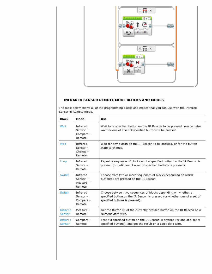
INFRARED SENSOR REMOTE MODE BLOCKS AND MODES
The table below shows all of the programming blocks and modes that you can use with the InfraredSensor in Remote mode.
Block Mode Use
Wait InfraredSensor –Compare -Remote
Wait for a specified button on the IR Beacon to be pressed. You can alsowait for one of a set of specified buttons to be pressed.
Wait InfraredSensor –Change -Remote
Wait for any button on the IR Beacon to be pressed, or for the buttonstate to change.
Loop InfraredSensor –Remote
Repeat a sequence of blocks until a specified button on the IR Beacon ispressed (or until one of a set of specified buttons is pressed).
Switch InfraredSensor –Measure –Remote
Choose from two or more sequences of blocks depending on whichbutton(s) are pressed on the IR Beacon.
Switch InfraredSensor –Compare -Remote
Choose between two sequences of blocks depending on whether aspecified button on the IR Beacon is pressed (or whether one of a set ofspecified buttons is pressed).
InfraredSensor
Measure -Remote
Get the Button ID of the currently pressed button on the IR Beacon on aNumeric data wire.
InfraredSensor
Compare -Remote
Test if a specified button on the IR Beacon is pressed (or one of a set ofspecified buttons), and get the result on a Logic data wire.

Using the Ultrasonic SensorINDEX
Home
General
ToolsProgramming BlocksData Logging
Getting StartedProgramsProject PropertiesConnecting to EV3Hardware PagePort SelectionData WiresData TypesContent EditorTeacher ModeManaging FilesEV3 Keyboard ShortcutsSupported TextDaisy ChainingPrinting
Using SensorsInfrared (IR)IR Beacon ModeIR Proximity ModeIR Remote ModeUltrasonicColorTimerTouchBrick ButtonsMotor RotationGyroNXT SoundTemperatureEnergy Meter
The Ultrasonic Sensor can measure the distance to an object infront of it. It does this by sending out sound waves andmeasuring how long it takes the sound to reflect back to thesensor. The sound frequency is too high for you to hear(“ultrasonic”).
You can measure the distance to an object in either inches orcentimeters. You could use this to, for example, make yourrobot stop a certain distance from a wall.
You can also use the Ultrasonic Sensor to detect whetheranother ultrasonic sensor nearby is operating. For example, youcould use this to detect the presence of another robot that isusing an ultrasonic sensor nearby. In this “listen only” mode,the sensor listens for sound signals but does not send them.
ULTRASONIC SENSOR DATA
The Ultrasonic Sensor can give the following data:
Data Type Range Notes
Distance inCentimeters
Numeric 0 to 255 Distance to object in centimeters.
Distance in Inches Numeric 0 to 100 Distance to object in inches.
UltrasoundDetected
Logic True/False True if another ultrasonic sensoris detected.
Tips and Tricks
• The Ultrasonic Sensor works best to detect objects with hard surfaces that reflectsound well. Soft objects, such as cloth, may absorb the sound waves and not bedetected. Objects with rounded or angled surfaces are also harder to detect.
• The sensor cannot detect objects that are very close to the sensor (closer thanabout 3 cm or 1.5 inches).
• The sensor has a wide “field of view” and may detect a closer object off to the sideinstead of a farther object straight ahead.
EXAMPLES USING THE ULTRASONIC SENSOR
Some examples of how you can use the Ultrasonic Sensor in your program are shownbelow. Example 1: Stop a Certain Distance before a Wall
Ultrasonic
Quick linksUltrasonic Sensor DataExamples Using the UltrasonicSensorUltrasonic Sensor Blocks andModes
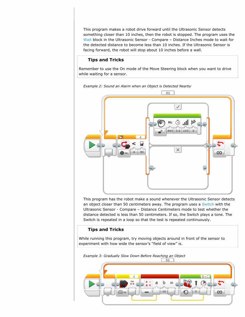
This program makes a robot drive forward until the Ultrasonic Sensor detectssomething closer than 10 inches, then the robot is stopped. The program uses theWait block in the Ultrasonic Sensor - Compare – Distance Inches mode to wait forthe detected distance to become less than 10 inches. If the Ultrasonic Sensor isfacing forward, the robot will stop about 10 inches before a wall.
Tips and Tricks
Remember to use the On mode of the Move Steering block when you want to drivewhile waiting for a sensor.
Example 2: Sound an Alarm when an Object is Detected Nearby
This program has the robot make a sound whenever the Ultrasonic Sensor detectsan object closer than 50 centimeters away. The program uses a Switch with theUltrasonic Sensor - Compare – Distance Centimeters mode to test whether thedistance detected is less than 50 centimeters. If so, the Switch plays a tone. TheSwitch is repeated in a loop so that the test is repeated continuously.
Tips and Tricks
While running this program, try moving objects around in front of the sensor toexperiment with how wide the sensor’s “field of view” is.
Example 3: Gradually Slow Down Before Reaching an Object

This program makes a robot gradually slow down and then stop about 10 cm awayfrom anything it detects in front of it. The closer it gets to the object, the slower itwill drive.
The program uses the Ultrasonic Sensor block in the Measure – DistanceCentimeters mode to get a distance measurement and get the resulting number ona data wire. A Math block then subtracts 10 from the distance, and the result iswired to the Power input of a Move Steering block. Shorter distances result in lowerpower, and when the distance reaches 10 cm, the power will be zero, and the robotwill stop. The process is repeated in a loop so that the motor power is adjustedcontinuously based on new distance measurements.
Tips and Tricks
You can also try moving the object while this program is running. The robot willcontinuously adjust its speed.
ULTRASONIC SENSOR BLOCKS AND MODES
The table below shows all of the programming blocks and modes that you can use withthe Ultrasonic Sensor. The Distance modes have sub-modes that let you choosebetween centimeters and inches.
Block Mode Use
Wait UltrasonicSensor -Compare –Distance
Wait for the distance to reach a certain value.
Wait UltrasonicSensor -Compare –Presence
Wait, in “listen only” mode, for an ultrasonicsignal to be detected.
Wait UltrasonicSensor -Change –Distance
Wait for the distance to change by a certainamount.
Loop UltrasonicSensor - Compare -Distance
Repeat a sequence of blocks until the distancereaches a certain value.
Loop Ultrasonic
Sensor –Compare -Presence
Repeat a sequence of blocks until an ultrasonic
signal is detected, in “listen only” mode.
Loop UltrasonicSensor –Change -Distance
Repeat a sequence of blocks until the distancechanges by a certain amount.
Switch UltrasonicSensor –
Choose between two sequences of blocks basedon the distance.

Sensor –Compare -Distance
on the distance.
Switch UltrasonicSensor –Compare -Presence
Choose between two sequences of blocks basedon whether an ultrasonic signal is detected in“listen only” mode.
UltrasonicSensor
Measure –Distance
Measure the distance and get the result on aNumeric data wire.
UltrasonicSensor
Measure –Presence
Listen for other ultrasonic signals in “listen only”mode, and get the result on a Logic data wire.
UltrasonicSensor
Compare –Distance
Compare the distance to a threshold, and get theresult on a Logic data wire.
UltrasonicSensor
Compare –Presence
Listen for other ultrasonic signals in “listen only”mode, and get the result on a Logic data wire.
UltrasonicSensor
Advanced Similar to Measure – Distance, but with the optionto make only a single sound ping.
DataLogging
See Data Logging.
Using the Color SensorINDEX
Home
General
ToolsProgramming BlocksData Logging
Getting StartedProgramsProject PropertiesConnecting to EV3Hardware PagePort SelectionData WiresData TypesContent EditorTeacher ModeManaging FilesEV3 Keyboard ShortcutsSupported TextDaisy ChainingPrinting
Using SensorsInfrared (IR)IR Beacon ModeIR Proximity ModeIR Remote ModeUltrasonicColorTimerTouchBrick ButtonsMotor RotationGyroNXT SoundTemperatureEnergy Meter
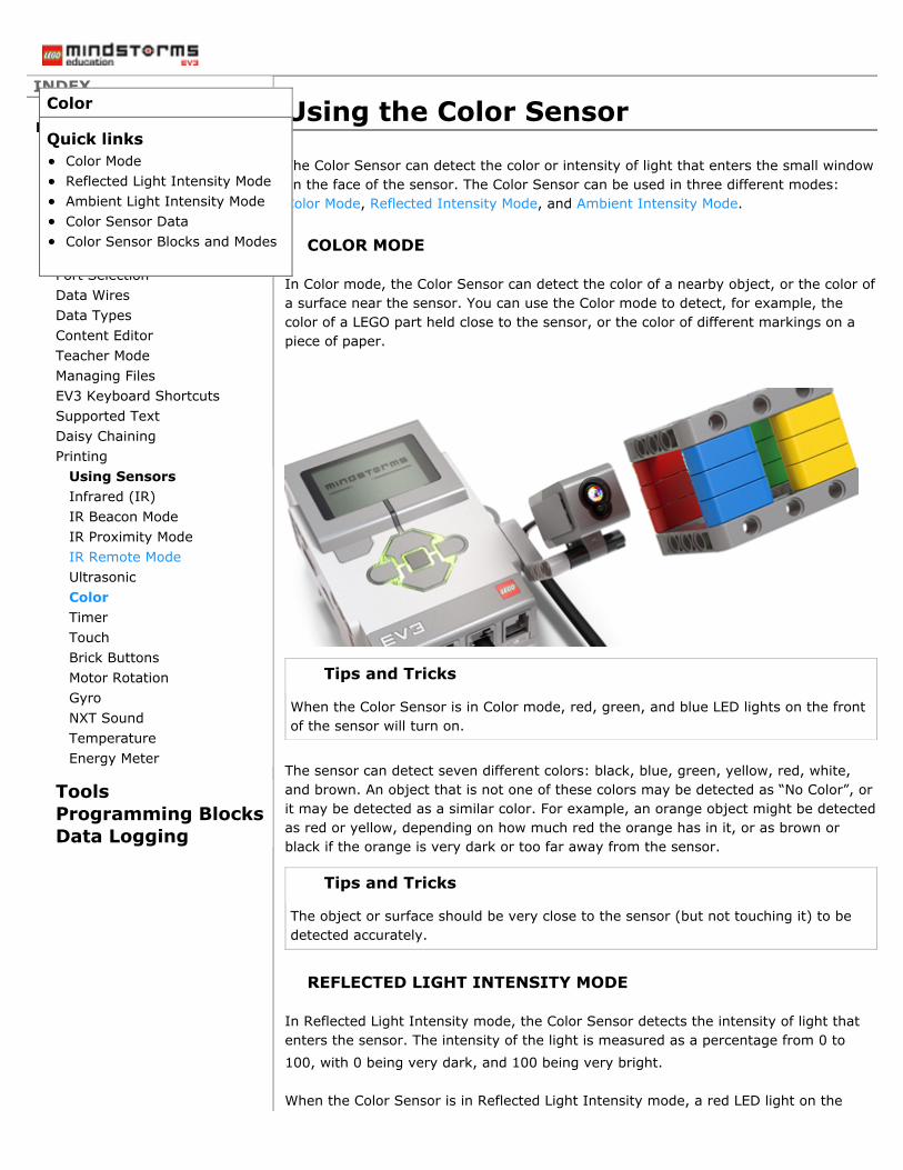
The Color Sensor can detect the color or intensity of light that enters the small windowon the face of the sensor. The Color Sensor can be used in three different modes:Color Mode, Reflected Intensity Mode, and Ambient Intensity Mode.
COLOR MODE
In Color mode, the Color Sensor can detect the color of a nearby object, or the color ofa surface near the sensor. You can use the Color mode to detect, for example, thecolor of a LEGO part held close to the sensor, or the color of different markings on apiece of paper.
Tips and Tricks
When the Color Sensor is in Color mode, red, green, and blue LED lights on the frontof the sensor will turn on.
The sensor can detect seven different colors: black, blue, green, yellow, red, white,and brown. An object that is not one of these colors may be detected as “No Color”, orit may be detected as a similar color. For example, an orange object might be detectedas red or yellow, depending on how much red the orange has in it, or as brown orblack if the orange is very dark or too far away from the sensor.
Tips and Tricks
The object or surface should be very close to the sensor (but not touching it) to bedetected accurately.
REFLECTED LIGHT INTENSITY MODE
In Reflected Light Intensity mode, the Color Sensor detects the intensity of light thatenters the sensor. The intensity of the light is measured as a percentage from 0 to100, with 0 being very dark, and 100 being very bright.
When the Color Sensor is in Reflected Light Intensity mode, a red LED light on the
Color
Quick linksColor ModeReflected Light Intensity ModeAmbient Light Intensity ModeColor Sensor DataColor Sensor Blocks and Modes
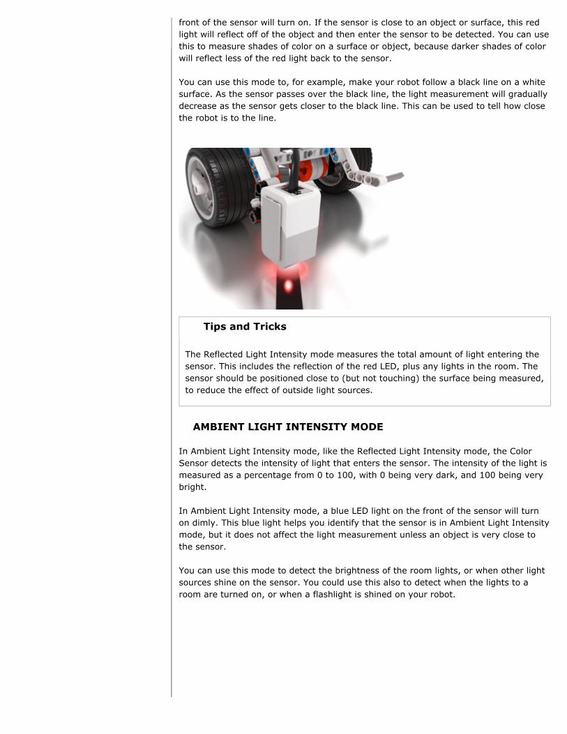
front of the sensor will turn on. If the sensor is close to an object or surface, this redlight will reflect off of the object and then enter the sensor to be detected. You can usethis to measure shades of color on a surface or object, because darker shades of colorwill reflect less of the red light back to the sensor.
You can use this mode to, for example, make your robot follow a black line on a whitesurface. As the sensor passes over the black line, the light measurement will graduallydecrease as the sensor gets closer to the black line. This can be used to tell how closethe robot is to the line.
Tips and Tricks
The Reflected Light Intensity mode measures the total amount of light entering thesensor. This includes the reflection of the red LED, plus any lights in the room. Thesensor should be positioned close to (but not touching) the surface being measured,to reduce the effect of outside light sources.
AMBIENT LIGHT INTENSITY MODE
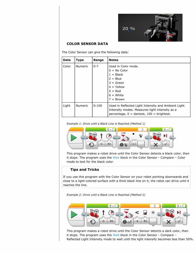
In Ambient Light Intensity mode, like the Reflected Light Intensity mode, the ColorSensor detects the intensity of light that enters the sensor. The intensity of the light ismeasured as a percentage from 0 to 100, with 0 being very dark, and 100 being verybright.
In Ambient Light Intensity mode, a blue LED light on the front of the sensor will turnon dimly. This blue light helps you identify that the sensor is in Ambient Light Intensitymode, but it does not affect the light measurement unless an object is very close tothe sensor.
You can use this mode to detect the brightness of the room lights, or when other lightsources shine on the sensor. You could use this also to detect when the lights to aroom are turned on, or when a flashlight is shined on your robot.
COLOR SENSOR DATA
The Color Sensor can give the following data:
Data Type Range Notes
Color Numeric 0-7 Used in Color mode.0 = No Color1 = Black2 = Blue3 = Green4 = Yellow5 = Red6 = White7 = Brown
Light Numeric 0-100 Used in Reflected Light Intensity and Ambient LightIntensity modes. Measures light intensity as apercentage, 0 = darkest, 100 = brightest.
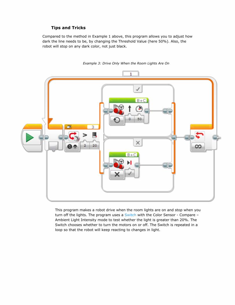
Example 1: Drive until a Black Line is Reached (Method 1)
This program makes a robot drive until the Color Sensor detects a black color, thenit stops. The program uses the Wait block in the Color Sensor - Compare – Colormode to test for the black color.
Tips and Tricks
If you use this program with the Color Sensor on your robot pointing downwards andclose to a light-colored surface with a thick black line on it, the robot can drive until itreaches the line.
Example 2: Drive until a Black Line is Reached (Method 2)
This program makes a robot drive until the Color Sensor detects a dark color, thenit stops. The program uses the Wait block in the Color Sensor - Compare –Reflected Light Intensity mode to wait until the light intensify becomes less than 50%.
Tips and Tricks
Compared to the method in Example 1 above, this program allows you to adjust howdark the line needs to be, by changing the Threshold Value (here 50%). Also, therobot will stop on any dark color, not just black.
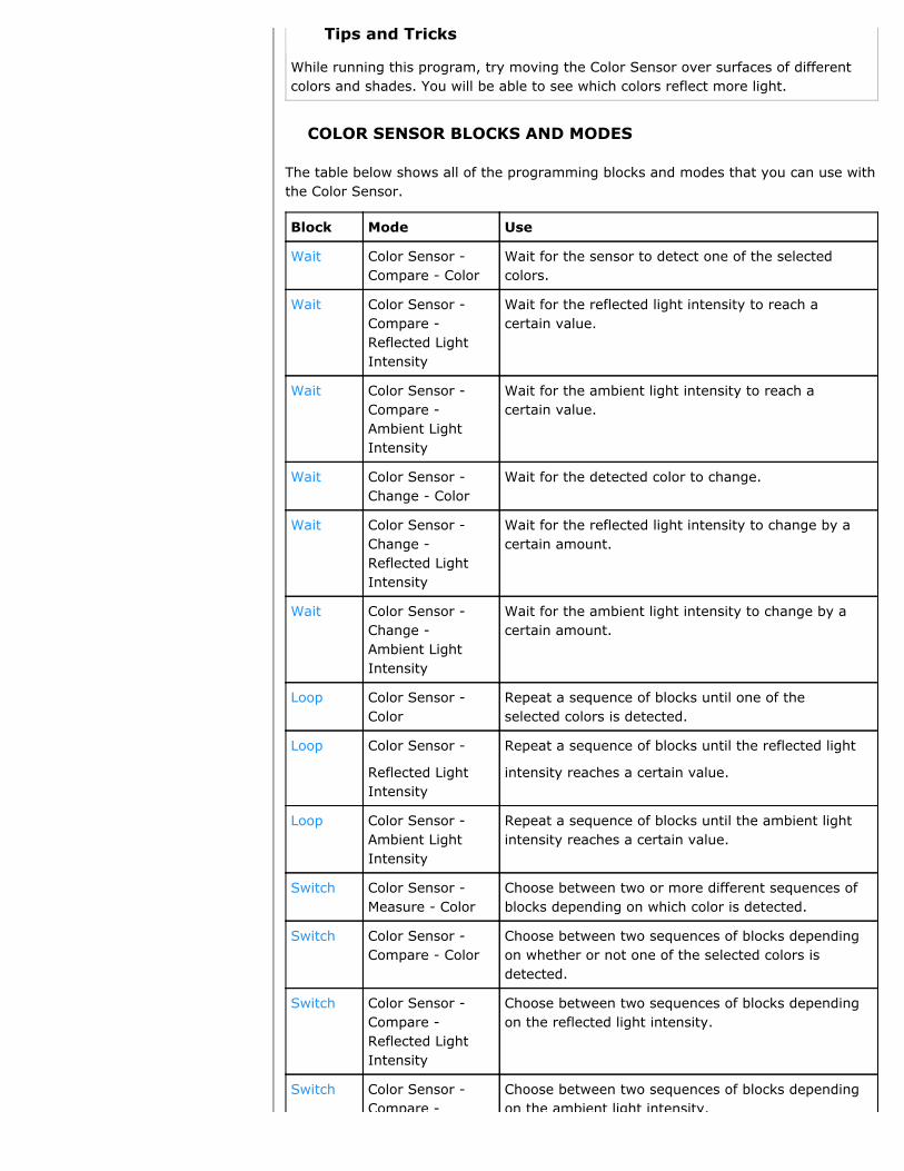
Example 3: Drive Only When the Room Lights Are On
This program makes a robot drive when the room lights are on and stop when youturn off the lights. The program uses a Switch with the Color Sensor - Compare –Ambient Light Intensity mode to test whether the light is greater than 20%. TheSwitch chooses whether to turn the motors on or off. The Switch is repeated in aloop so that the robot will keep reacting to changes in light.

This program puts a graphical light meter on the EV3 Display. The program uses aColor Sensor block in the Measure – Reflected Light Intensity mode to measure thereflected light (0-100) and get the result on a data wire. The result is thenmultiplied by 1.78 to scale it to the EV3 screen width (178 pixels) and then used asthe width of a filled rectangle shape. The process is repeated in a loop so that thedisplay is continuously updated.
This program makes the EV3 say “Red”, “Green”, and “Blue” when the Color Sensordetects these colors. The program uses a Switch in the Color Sensor – Measure –Color mode to choose between different Sound blocks based on the color that isdetected. A “No Color” case is added and selected as the default so that the EV3won’t say anything when one of the three colors is not seen.
Example 4: Say “Red”, “Green”, and “Blue” when Detected
Tips and Tricks
While running this program, try moving the Color Sensor over surfaces of differentcolors and shades. You will be able to see which colors reflect more light.
COLOR SENSOR BLOCKS AND MODES
The table below shows all of the programming blocks and modes that you can use withthe Color Sensor.
Block Mode Use
Wait Color Sensor -Compare - Color
Wait for the sensor to detect one of the selectedcolors.
Wait Color Sensor -Compare -Reflected LightIntensity
Wait for the reflected light intensity to reach acertain value.
Wait Color Sensor -Compare -Ambient LightIntensity
Wait for the ambient light intensity to reach acertain value.
Wait Color Sensor -Change - Color
Wait for the detected color to change.
Wait Color Sensor -Change -Reflected LightIntensity
Wait for the reflected light intensity to change by acertain amount.
Wait Color Sensor -Change -Ambient LightIntensity
Wait for the ambient light intensity to change by acertain amount.
Loop Color Sensor -Color
Repeat a sequence of blocks until one of theselected colors is detected.
Loop Color Sensor -
Reflected LightIntensity
Repeat a sequence of blocks until the reflected light
intensity reaches a certain value.
Loop Color Sensor -Ambient LightIntensity
Repeat a sequence of blocks until the ambient lightintensity reaches a certain value.
Switch Color Sensor -Measure - Color
Choose between two or more different sequences ofblocks depending on which color is detected.
Switch Color Sensor -Compare - Color
Choose between two sequences of blocks dependingon whether or not one of the selected colors isdetected.
Switch Color Sensor -Compare -Reflected LightIntensity
Choose between two sequences of blocks dependingon the reflected light intensity.
Switch Color Sensor -Compare -
Choose between two sequences of blocks dependingon the ambient light intensity.

Compare -Ambient LightIntensity
on the ambient light intensity.
ColorSensor
Measure - Color Measure the detected color (0-7) and get the resulton a Numeric data wire.
ColorSensor
Measure -Reflected LightIntensity
Measure the reflected light intensity (0-100) andget the result on a Numeric data wire.
ColorSensor
Measure -Ambient LightIntensity
Measure the ambient light intensity (0-100) and getthe result on a Numeric data wire.
ColorSensor
Compare - Color Compare the detected color to one or more selectedcolors, and get the result on a Logic data wire (Trueif it matches any of the selected colors).
ColorSensor
Compare -Reflected LightIntensity
Compare the reflected light intensity to a threshold,and get the result on a Logic data wire.
ColorSensor
Compare -Ambient LightIntensity
Compare the ambient light intensity to a threshold,and get the result on a Logic data wire.
DataLogging
See Data Logging.

Using the TimerINDEX
Home
General
ToolsProgramming BlocksData Logging
Getting StartedProgramsProject PropertiesConnecting to EV3Hardware PagePort SelectionData WiresData TypesContent EditorTeacher ModeManaging FilesEV3 Keyboard ShortcutsSupported TextDaisy ChainingPrinting
Using SensorsInfrared (IR)IR Beacon ModeIR Proximity ModeIR Remote ModeUltrasonicColorTimerTouchBrick ButtonsMotor RotationGyroNXT SoundTemperatureEnergy Meter
The Timer can be used to measure time intervals. The Timer is used like a sensor, butit is internal to the EV3 Brick and does not require a sensor port. You could use theTimer to measure, for example, how long it takes your robot to move a certaindistance.
The EV3 has eight timers, so you can time up to eight different things together. Youcan reset a timer to zero at any point in your program, and it will start timing fromthat point.
Tips and Tricks
If you simply want to wait for a certain amount of time in your program, you can usethe Wait block in the Wait Time mode. Using the Timer lets you reset the timer andtest the timer at different places in your program.
TIMER DATA
The Timer gives the following data:
Data Type Notes
ElapsedTime
Numeric Elapsed time since the timer was last reset, inseconds.
Tips and Tricks
Tip: Time is measured in seconds using a decimal number. An interval of one tenth ofa second would result in an Elapsed Time of 0.1 seconds.
RESETTING A TIMER
You can reset a timer to zero (0.0 seconds) at any point in your program by using theTimer block in Reset mode. After a timer is reset, it starts timing again immediatelyfrom zero. All eight timers are automatically reset at the beginning of a program andare always running.
Tips and Tricks
If you measure a timer that has never been reset, you will get the elapsed time sincethe program started.
EXAMPLES USING THE TIMER
Examples of how you can use the Timer in your program are shown below.
Example 1: Make a Motor Move Once every Second
Timer
Quick linksTimer DataResetting a TimerExamples Using the TimerTimer Blocks and Modes

This program makes a motor turn 45 degrees exactly once every second, like aticking clock. The program uses the Medium Motor block to turn the motor by 45degrees, which will take a bit of time, but less than 1 second. Then the programneeds to wait for the remainder of the 1-second interval to end before moving themotor again. To do this, the program starts timer 1 before starting the motor byusing the Timer block in Reset mode. Then after the motor stops, a Wait block inTimer – Compare - Time mode waits for timer 1 to reach 1 second. This will makethe total interval 1 second, including both the time the motor is moving and thetime it is stopped.
Example 2: Measure How Long a Touch Sensor is Held in
This program measures how long the touch sensor is held in each time it ispressed, and the result in seconds is displayed on the EV3 Display. The programuses the Wait block to wait for a touch sensor press and then again to wait for therelease. After the press, timer 1 is reset using the Timer block in Reset mode. Afterthe release, the elapsed time for timer 1 is measured using the Timer block inMeasure – Time mode. The resulting number is wired to a Display block to displaythe number in seconds.
TIMER BLOCKS AND MODES
The table below shows all of the programming blocks and modes that you can use withTimer.
Block Mode Use
Wait Timer - Compare– Time
Wait for a timer to reach a certain value.
Wait Timer – Change- Time
Wait for a timer to change by a certain amount.
Loop Timer Repeat a sequence of blocks until a timer reaches acertain value.
Switch Timer Choose between two sequences of blocks based on atimer.
Timer Measure Read a timer, and get the result in seconds on aNumeric data wire.
Timer Compare Compare a timer to a threshold, and get the resulton a Logic data wire.
Timer Reset Reset a timer to zero. The timer starts timing againimmediately.
Tips and Tricks

Tips and Tricks
Simple uses of timers may also be able to use the following blocks and modes:
Block Mode Use
Wait Time Wait for a certain amount of time.
Loop Time Repeat a sequence of blocks for a certain amount of time.
Using the Touch SensorINDEX
Home
General
ToolsProgramming BlocksData Logging
Getting StartedProgramsProject PropertiesConnecting to EV3Hardware PagePort SelectionData WiresData TypesContent EditorTeacher ModeManaging FilesEV3 Keyboard ShortcutsSupported TextDaisy ChainingPrinting
Using SensorsInfrared (IR)IR Beacon ModeIR Proximity ModeIR Remote ModeUltrasonicColorTimerTouchBrick ButtonsMotor RotationGyroNXT SoundTemperatureEnergy Meter
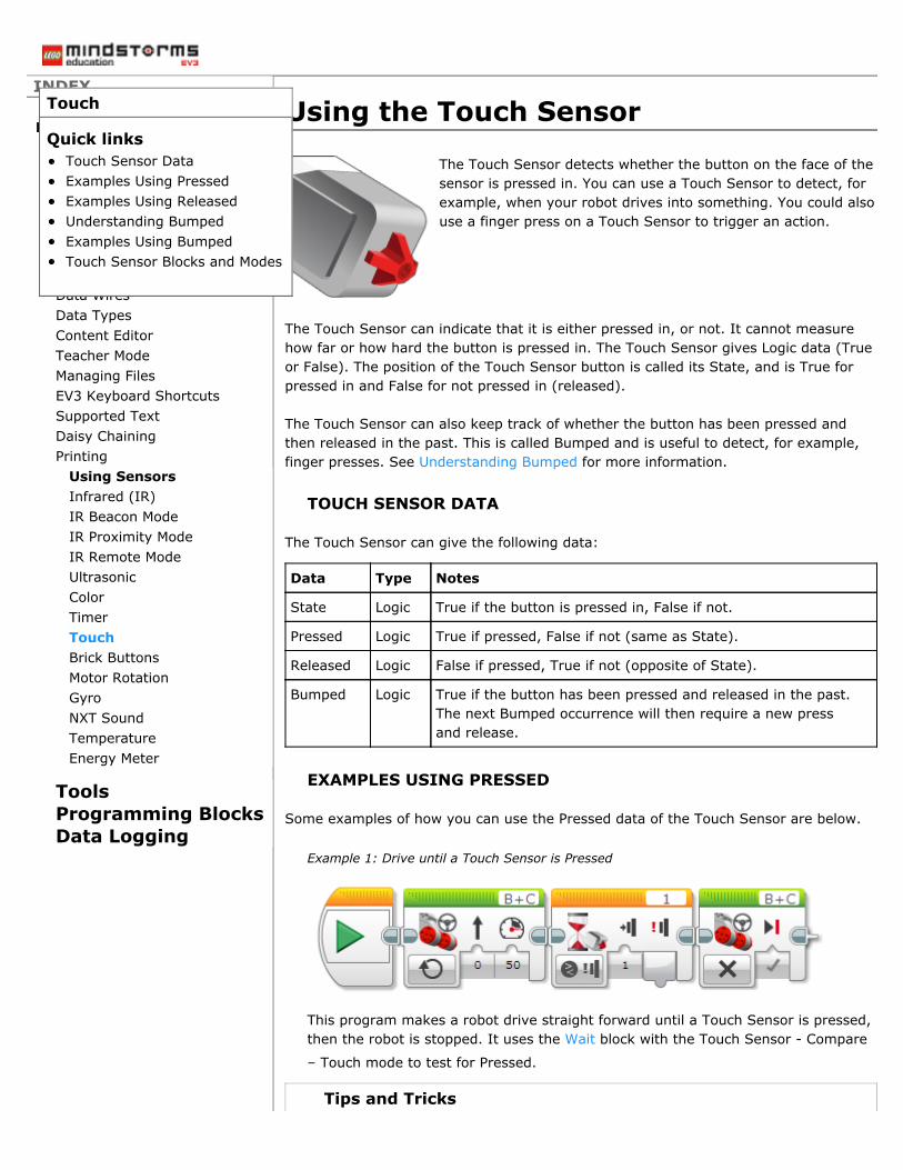
The Touch Sensor detects whether the button on the face of thesensor is pressed in. You can use a Touch Sensor to detect, forexample, when your robot drives into something. You could alsouse a finger press on a Touch Sensor to trigger an action.
The Touch Sensor can indicate that it is either pressed in, or not. It cannot measurehow far or how hard the button is pressed in. The Touch Sensor gives Logic data (Trueor False). The position of the Touch Sensor button is called its State, and is True forpressed in and False for not pressed in (released).
The Touch Sensor can also keep track of whether the button has been pressed andthen released in the past. This is called Bumped and is useful to detect, for example,finger presses. See Understanding Bumped for more information.
TOUCH SENSOR DATA
The Touch Sensor can give the following data:
Data Type Notes
State Logic True if the button is pressed in, False if not.
Pressed Logic True if pressed, False if not (same as State).
Released Logic False if pressed, True if not (opposite of State).
Bumped Logic True if the button has been pressed and released in the past.The next Bumped occurrence will then require a new pressand release.
EXAMPLES USING PRESSED
Some examples of how you can use the Pressed data of the Touch Sensor are below.
Example 1: Drive until a Touch Sensor is Pressed
This program makes a robot drive straight forward until a Touch Sensor is pressed,then the robot is stopped. It uses the Wait block with the Touch Sensor - Compare
– Touch mode to test for Pressed.
Tips and Tricks
Touch
Quick linksTouch Sensor DataExamples Using PressedExamples Using ReleasedUnderstanding BumpedExamples Using BumpedTouch Sensor Blocks and Modes

Remember to use the On mode of the Move Steering block when you want to drivewhile waiting for a sensor.
Example 2: Run a Motor whenever a Touch Sensor is Held in (Method 1)
This program makes a motor run whenever the Touch Sensor is pressed and heldin. The motor is stopped whenever the Touch Sensor is released. The program usesa Switch block with the Touch Sensor - Compare – Touch mode to test for Pressed.The result of the test is used to choose between turning the motor on or off. Thetest is repeated continuously in a Loop.
Example 3: Make the Brick Status Light Pulse whenever a Touch Sensor is Held in
This program turns the Brick Status Light on in orange, and makes it pulsewhenever the Touch Sensor is held in. It uses the Touch Sensor block in Measure
mode to get the state of the Touch Sensor. The result is wired to the Pulse input ofthe Brick Buttons block with a Logic data wire.
EXAMPLES USING RELEASED
Some examples of how you can use the Released data of the Touch Sensor are below.

Some examples of how you can use the Released data of the Touch Sensor are below.
Example 4: Beep on each Touch Sensor Press
This program sounds a short tone each time the Touch Sensor is pressed. Only onetone is sounded for each press. The program uses a Wait block in the Touch Sensor- Compare – Touch mode to test for Pressed and then another Wait block to waitfor Released before letting the loop continue.
Tips and Tricks
If you delete the Wait for Release from this program, you will find that the tone willrepeat as long as the Touch Sensor is held in. This is because the Wait for Pressedwill immediately continue to the next block if the Touch Sensor is already pressed.Try it!
Example 5: Run a Motor whenever a Touch Sensor is Held in (Method 2)
This program makes a motor run whenever the Touch Sensor is pressed and heldin. The motor is stopped whenever the Touch Sensor is released. The program usesa Wait block in the Touch Sensor - Compare – Touch mode to wait for Pressed tostart the motor, then another Wait to wait for Released before stopping the motor.The process is repeated in a Loop.
Tips and Tricks
This program does the same thing as Example 2 above, using a different method.
UNDERSTANDING BUMPED
In addition to telling you whether the Touch Sensor button is currently pressed orreleased, the Touch Sensor also keeps track of whether it has been pressed andreleased in the past, which is called Bumped. This makes it easy to find out whether aTouch Sensor has been pressed like a pushbutton, without needing to check itconstantly for a press and then wait for the release.
Once a Touch Sensor indicates that it has been Bumped, it will not indicate Bumpedagain until the Touch Sensor is pressed and then released a new time. This makes iteasy to make sure that, for example, each press corresponds to an action happeningonly once.

only once.
The table below shows an example where a Touch Sensor is pressed and releasedtwice as a series of steps. The table shows the result of a program testing for Pressed,Released, and Bumped after each action.
Step Action Pressed Released Bumped
1 Button starts released False True False
2 Button is pressed in True False False
3 Button is released False True True
4 Button is still released, and theprogram tests the Touch Sensoragain
False True False
5 Button is pressed a second time True False False
6 Button is held in, and the programtests the Touch Sensor again
True False False
7 Button is released False True True
8 Button is still released, and theprogram tests the Touch Sensoragain
False True False
Note that when the button is held in, the Touch Sensor will continue to indicatePressed each time the program tests it. However, once the button is released, thesensor will only indicate Bumped the first time the program tests it for Bumped. Thesensor will not indicate Bumped again until it is pressed and released a new time.
EXAMPLES USING BUMPED
Some examples of how you can use the Bumped data of the Touch Sensor are shownbelow.
Example 6: Change the Display when the Touch Sensor is Pressed
This program will make the EV3 Brick Display show “Zero”, then “One”, then “Two”,changing the Display each time the Touch Sensor is bumped (pressed and thenreleased).
Tips and Tricks
If you change the Wait for blocks in this program to test for Pressed instead ofBumped, you will find that the display goes from “Zero” directly to “Two”, skipping“One”. Try it! This is because the Display blocks execute so quickly that when thesecond Wait for Pressed test happens, your finger is still holding the button in fromthe first press, so the second Wait for ends immediately. When testing for Bumped,only one test will succeed for each different press.
Example 7: Drive in a Pattern until the Touch Sensor is Pressed

This program makes a robot repeat a pattern of driving straight and then turning,until a Touch Sensor, acting as a “Stop” button on the robot, is pressed. After theTouch Sensor is pressed, the robot will stop after the next turn. The program usesa Loop in Touch Sensor mode to repeat the driving until the Touch Sensor isBumped (pressed and then released).
Tips and Tricks
If you try this program using Pressed instead of Bumped, you will find that pressingthe Touch Sensor usually does not make the robot stop. Try it! This is because theloop tests the sensor only briefly after the two Move blocks have completed. If youpress and release the sensor while the Move blocks are running, the Pressed statewill not be seen. Using Bumped, the Touch Sensor remembers that it was pressedand released in the past.
TOUCH SENSOR BLOCKS AND MODES
The table below shows all of the programming blocks and modes that you can use withthe Touch Sensor.
Block Mode Use
Wait TouchSensor –Compare
Wait for the Touch Sensor to be Pressed, Released, orBumped.
Wait TouchSensor -Change
Wait for the Touch Sensor state to change.
Loop TouchSensor
Repeat a sequence of blocks until the Touch Sensor isPressed, Released, or Bumped.
Switch TouchSensor
Choose between two sequences of blocks depending onwhether the Touch Sensor is Pressed or not, Released ornot, or Bumped or not.
TouchSensor
Measure Get the current Touch Sensor state (Pressed or not) on aLogic data wire.
TouchSensor
Compare Test the Touch Sensor for Pressed, Released, or Bumped,and get the result on a Logic data wire.
DataLogging
See Data Logging.


Using the Brick ButtonsINDEX
Home
General
ToolsProgramming BlocksData Logging
Getting StartedProgramsProject PropertiesConnecting to EV3Hardware PagePort SelectionData WiresData TypesContent EditorTeacher ModeManaging FilesEV3 Keyboard ShortcutsSupported TextDaisy ChainingPrinting
Using SensorsInfrared (IR)IR Beacon ModeIR Proximity ModeIR Remote ModeUltrasonicColorTimerTouchBrick ButtonsMotor RotationGyroNXT SoundTemperatureEnergy Meter
The Brick Buttons are the five buttons (Left, Center, Right, Up, and Down) on the faceof the EV3 Brick. You can use the Brick Buttons like a sensor to detect if a button ispressed, and to find out which button is pressed.
You can use the Brick Buttons to make your program respond to button presses. Forexample, you could make a robot arm lift up and down when the Up and Down buttonsare pressed.
Tips and Tricks
The Back button on the EV3 is not included in the Brick Buttons. Pressing the Backbutton aborts a running program.
The Brick Buttons can also keep track of whether a button has been pressed and thenreleased in the past. This is called Bumped, and it works the same as the Bumpedstate of the Touch Sensor. See Understanding Bumped Using the Touch Sensor – formore information.
BRICK BUTTONS DATA
The Brick Buttons can give the following data:
Data Type Notes
ButtonID
Numeric Indicates which button is currently pressed:0 = None1 = Left2 = Center3 = Right4 = Up5 = Down
Pressed Logic For a specified Button ID (1-5), True if the button is
pressed, False if not.
Released Logic For a specified Button ID (1-5), False if the button ispressed, True if not.
Brick Buttons
Quick linksBrick Buttons DataExamples Using the BrickButtonsBrick Buttons Blocks and Modes
pressed, True if not.
Bumped Logic For a specified Button ID (1-5), True if the button has beenpressed and released in the past. The next Bumpedoccurrence will then require a new press and release.
Tips and Tricks
The Brick Buttons cannot detect when more than one button is pressed at the sametime. If you press two buttons at the same time, one button will override the other.
EXAMPLES USING THE BRICK BUTTONS
Some examples of how you can use the Brick Buttons in a program are below.
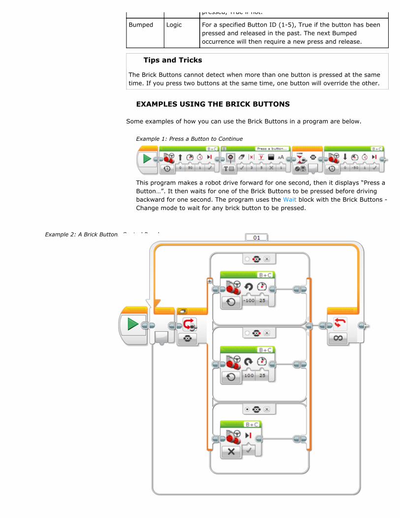
Example 1: Press a Button to Continue
This program makes a robot drive forward for one second, then it displays “Press aButton…”. It then waits for one of the Brick Buttons to be pressed before drivingbackward for one second. The program uses the Wait block with the Brick Buttons -Change mode to wait for any brick button to be pressed.
Example 2: A Brick Buttons Control Panel
This program makes a robot turn left when the Left button is pressed, and turnright when the Right button is pressed. The program uses a Switch block with theBrick Buttons - Measure mode to find out which of the Brick Buttons is pressed. Thethree different cases in the Switch make the robot: turn left when the Left button ispressed, turn right when the Right button is pressed, and stop when no button ispressed. The test is repeated continuously in a Loop.
Tips and Tricks
Try using the “+” button on the Switch to add more cases. For example, you mightmake the robot drive forward and backward when you press the Up and Downbuttons.
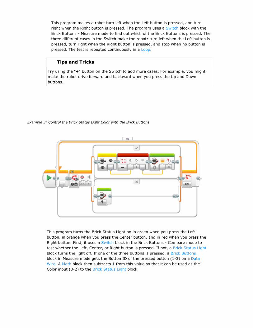
Example 3: Control the Brick Status Light Color with the Brick Buttons
This program turns the Brick Status Light on in green when you press the Leftbutton, in orange when you press the Center button, and in red when you press theRight button. First, it uses a Switch block in the Brick Buttons - Compare mode totest whether the Left, Center, or Right button is pressed. If not, a Brick Status Lightblock turns the light off. If one of the three buttons is pressed, a Brick Buttonsblock in Measure mode gets the Button ID of the pressed button (1-3) on a DataWire. A Math block then subtracts 1 from this value so that it can be used as theColor input (0-2) to the Brick Status Light block.
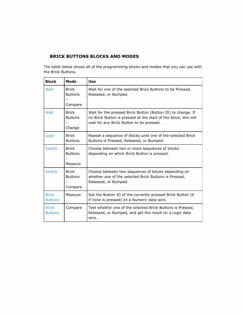
BRICK BUTTONS BLOCKS AND MODES
The table below shows all of the programming blocks and modes that you can use withthe Brick Buttons.
Block Mode Use
Wait BrickButtons–Compare
Wait for one of the selected Brick Buttons to be Pressed,Released, or Bumped.
Wait BrickButtons–Change
Wait for the pressed Brick Button (Button ID) to change. Ifno Brick Button is pressed at the start of the block, this willwait for any Brick Button to be pressed.
Loop BrickButtons
Repeat a sequence of blocks until one of the selected BrickButtons is Pressed, Released, or Bumped.
Switch BrickButtons-Measure
Choose between two or more sequences of blocksdepending on which Brick Button is pressed.
Switch BrickButtons-Compare
Choose between two sequences of blocks depending onwhether one of the selected Brick Buttons is Pressed,Released, or Bumped.
BrickButtons
Measure Get the Button ID of the currently pressed Brick Button (0if none is pressed) on a Numeric data wire.
BrickButtons
Compare Test whether one of the selected Brick Buttons is Pressed,Released, or Bumped, and get the result on a Logic datawire.

Using the Motor Rotation SensorINDEX
Home
General
ToolsProgramming BlocksData Logging
Getting StartedProgramsProject PropertiesConnecting to EV3Hardware PagePort SelectionData WiresData TypesContent EditorTeacher ModeManaging FilesEV3 Keyboard ShortcutsSupported TextDaisy ChainingPrinting
Using SensorsInfrared (IR)IR Beacon ModeIR Proximity ModeIR Remote ModeUltrasonicColorTimerTouchBrick ButtonsMotor RotationGyroNXT SoundTemperatureEnergy Meter
The Motor Rotation sensor is used to measure how far a motor has turned. A rotationsensor is built into the Medium Motor, the Large Motor, and the NXT Motor. Thesensors in these motors can detect an amount of rotation in degrees. A full turn of amotor is 360 degrees of rotation.
You can also use the Motor Rotation sensor to find out what power level a motor iscurrently running at.
Tips and Tricks
A Motor Rotation sensor is used with a motor that is connected to a motor port onthe EV3 Brick (A, B, C, or D). Motor Rotation sensors cannot be used with the EV3sensor ports (1, 2, 3, and 4).
MOTOR ROTATION DATA
A Motor Rotation sensor can give the following data:
Data Type Notes
Degrees Numeric Amount of rotation in degrees
Rotations Numeric Amount of rotation expressed in rotations (degrees/360,as a decimal number)
CurrentPower
Numeric Current motor power level if the motor is running (1-100),or 0 if the motor is stopped
RESETTING A MOTOR ROTATION SENSOR
A Motor Rotation sensor can be reset to zero at any point in a program. The sensor willthen measure the total amount of rotation relative to the reset point. To reset a MotorRotation sensor, use the Motor Rotation block in the Reset mode.
Tips and Tricks
If you measure a Motor Rotation sensor that has never been reset, you will get thetotal amount of rotation that the motor has turned since the program started.
MOTOR ROTATION DIRECTION AND TOTAL ROTATION
Forward rotation of a motor results in a positive number of degrees or rotations, andbackward rotation results in a negative number. Rotation is always measured as thetotal amount of forward rotation since the sensor was last reset. Backward rotation is
Motor Rotation
Quick linksMotor Rotation DataResetting a Motor RotationSensorMotor Rotation Direction andTotal RotationExamples Using the MotorRotation SensorMotor Rotation Blocks and Modes

subtracted from any accumulated forward rotation.
The table below shows an example of motor actions happening in several steps and theresult of measuring the motor rotation after each step.
Step Action Motor Rotation isthen:
1 Program starts, motor has not turned yet 0 degrees
2 Motor turns forward one full turn (360degrees)
360 degrees
3 Motor turns forward one full turn again 720 degrees
4 Motor turns forward 60 degrees 780 degrees
5 Motor turns backward for 30 degrees 750 degrees
6 Motor Rotation is reset 0 degrees
7 Motor turns backward for 100 degrees -100 degrees
8 Motor turns backward for 60 degrees -160 degrees
9 Motor turns forward for 360 degrees 200 degrees
EXAMPLES USING THE MOTOR ROTATION SENSOR
Some examples of how you can use the Motor Rotation sensor in your program areshown below.
Example 1: Make a Sound when your Robot is Pushed
This program makes a robot make a sound when it is pushed by hand so that thewheels move a little bit. The program uses the Wait block in the Motor Rotations –Change – Degrees mode to wait for the rotation sensor for motor C to change by 5degrees in either direction. Then a Sound block makes a sound.
Example 2: Drive in a Pattern for a Certain Distance
This program makes a robot drive straight for 2 rotations and then drive in a zigzagpattern for 6.5 total rotations. It drives in a zigzag pattern by moving first onewheel, then the other. The zigzag pattern is repeated in a Loop until motor B hasdriven a total of 6.5 rotations. The program uses the loop in the Motor Rotation –Rotations mode to stop the loop when the rotation sensor for motor B measures atotal of 6.5 rotations. To make the 6.5 rotations measure only the zigzag driving,not including the 2 straight rotations in the beginning, the rotation sensor for motorB is reset to zero before the zigzag driving using the Motor Rotation block in theReset mode.

Reset mode.
Example 3: A Speed Control Dial
This program makes the motor connected to port C act like a speed control dial forthe motor connected to port B. Turning the C motor forward and backward by handwill control the speed of the B motor. The program uses the Motor Rotation block inthe Measure – Degrees mode to measure the degrees turned by motor C. Thisresult is used for the Power input of a Large Motor block and also displayed using aDisplay block. The process is repeated in a Loop so that the speed is continuouslyupdated.
Tips and Tricks
If the Power input to the Large Motor block is greater than 100, it will use 100%power.
MOTOR ROTATION BLOCKS AND MODES
The table below shows the programming blocks and modes that you can use with theMotor Rotation Sensor.
Block Mode Use
Wait MotorRotation -Compare
Wait for a rotation sensor to reach a certain value(Degrees, Rotations, or Current Power).
Wait MotorRotation -Change
Wait for a rotation sensor to change by a certain amount(Degrees, Rotations, or Current Power).
Loop MotorRotation
Repeat a sequence of blocks until a rotation sensorreaches a certain value (Degrees, Rotations, or CurrentPower).
Switch MotorRotation
Choose between two sequences of blocks based on arotation sensor (Degrees, Rotations, or Current Power).
Motor
Rotation
Measure Read a rotation sensor (Degrees, Rotations, or Current
Power), and get the result on a Numeric data wire.
MotorRotation
Compare Compare a rotation sensor (Degrees, Rotations, orCurrent Power) to a threshold, and get the result on aLogic data wire.
MotorRotation
Reset Reset a rotation sensor to zero.
DataLogging
See Data Logging.Logging
Tips and Tricks
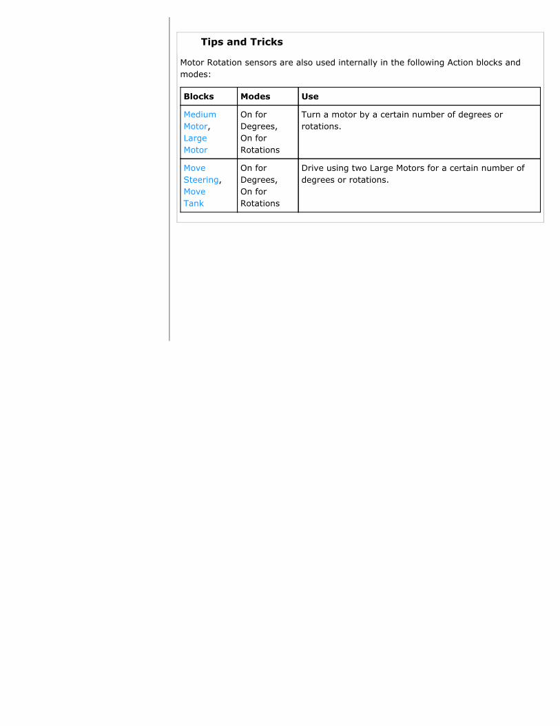
Motor Rotation sensors are also used internally in the following Action blocks andmodes:
Blocks Modes Use
MediumMotor,LargeMotor
On forDegrees,On forRotations
Turn a motor by a certain number of degrees orrotations.
MoveSteering,MoveTank
On forDegrees,On forRotations
Drive using two Large Motors for a certain number ofdegrees or rotations.
Using the Gyro SensorINDEX
Home
General
ToolsProgramming BlocksData Logging
Getting StartedProgramsProject PropertiesConnecting to EV3Hardware PagePort SelectionData WiresData TypesContent EditorTeacher ModeManaging FilesEV3 Keyboard ShortcutsSupported TextDaisy ChainingPrinting
Using SensorsInfrared (IR)IR Beacon ModeIR Proximity ModeIR Remote ModeUltrasonicColorTimerTouchBrick ButtonsMotor RotationGyroNXT SoundTemperatureEnergy Meter
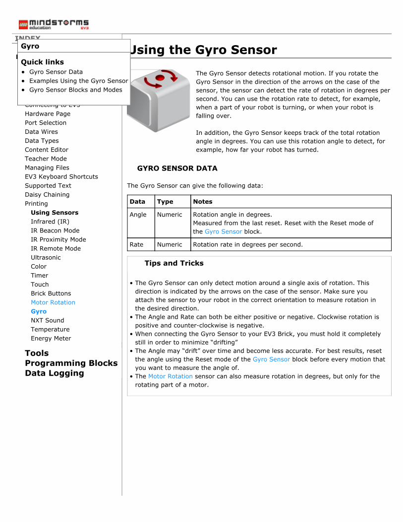
The Gyro Sensor detects rotational motion. If you rotate theGyro Sensor in the direction of the arrows on the case of thesensor, the sensor can detect the rate of rotation in degrees persecond. You can use the rotation rate to detect, for example,when a part of your robot is turning, or when your robot isfalling over.
In addition, the Gyro Sensor keeps track of the total rotationangle in degrees. You can use this rotation angle to detect, forexample, how far your robot has turned.
GYRO SENSOR DATA
The Gyro Sensor can give the following data:
Data Type Notes
Angle Numeric Rotation angle in degrees.Measured from the last reset. Reset with the Reset mode ofthe Gyro Sensor block.
Rate Numeric Rotation rate in degrees per second.
Tips and Tricks
• The Gyro Sensor can only detect motion around a single axis of rotation. Thisdirection is indicated by the arrows on the case of the sensor. Make sure youattach the sensor to your robot in the correct orientation to measure rotation inthe desired direction.
• The Angle and Rate can both be either positive or negative. Clockwise rotation ispositive and counter-clockwise is negative.
• When connecting the Gyro Sensor to your EV3 Brick, you must hold it completelystill in order to minimize “drifting”
• The Angle may “drift” over time and become less accurate. For best results, resetthe angle using the Reset mode of the Gyro Sensor block before every motion thatyou want to measure the angle of.
• The Motor Rotation sensor can also measure rotation in degrees, but only for therotating part of a motor.
Gyro
Quick linksGyro Sensor DataExamples Using the Gyro SensorGyro Sensor Blocks and Modes
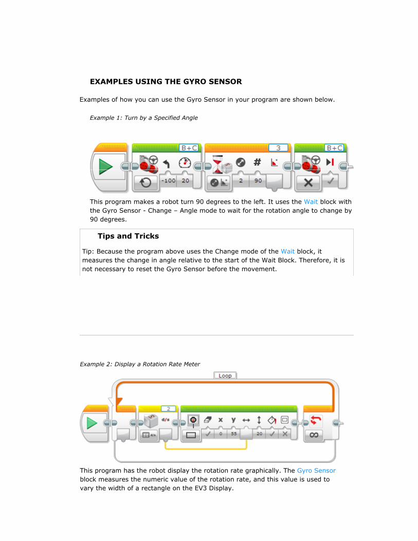
This program makes a robot turn 90 degrees to the left. It uses the Wait block withthe Gyro Sensor - Change – Angle mode to wait for the rotation angle to change by90 degrees.
Tips and Tricks
Tip: Because the program above uses the Change mode of the Wait block, itmeasures the change in angle relative to the start of the Wait Block. Therefore, it isnot necessary to reset the Gyro Sensor before the movement.
Example 2: Display a Rotation Rate Meter
This program has the robot display the rotation rate graphically. The Gyro Sensorblock measures the numeric value of the rotation rate, and this value is used tovary the width of a rectangle on the EV3 Display.
EXAMPLES USING THE GYRO SENSOR
Examples of how you can use the Gyro Sensor in your program are shown below.
Example 1: Turn by a Specified Angle

GYRO SENSOR BLOCKS AND MODES
The table below shows the programming blocks and modes that you can use with theGyro Sensor.
Block Mode Use
Wait Gyro Sensor- Compare
Wait for the rotation angle or rate to reach a certainvalue.
Wait Gyro Sensor- Change
Wait for the rotation angle or rate to change by acertain amount.
Loop Gyro Sensor Repeat a sequence of blocks until the rotation angle orrate reaches a certain value.
Switch Gyro Sensor Choose between two sequences of blocks based on therotation angle or rate.
GyroSensor
Measure Measure the rotation angle and/or rate, and get theresult on a Numeric data wire.
GyroSensor
Compare Compare the rotation angle or rate to a threshold, andget the result on a Logic data wire.
GyroSensor
Reset Reset the rotation angle to zero.
DataLogging
Gyro AngleGyro Rate
See Data Logging.

Using the NXT Sound SensorINDEX
Home
General
ToolsProgramming BlocksData Logging
Getting StartedProgramsProject PropertiesConnecting to EV3Hardware PagePort SelectionData WiresData TypesContent EditorTeacher ModeManaging FilesEV3 Keyboard ShortcutsSupported TextDaisy ChainingPrinting
Using SensorsInfrared (IR)IR Beacon ModeIR Proximity ModeIR Remote ModeUltrasonicColorTimerTouchBrick ButtonsMotor RotationGyroNXT SoundTemperatureEnergy Meter
The NXT Sound Sensor measures the intensity (volume) of sound using themicrophone on the face of the sensor. For example, you can use the sound sensor tomake your robot react to a loud sound such a hand clap.
SOUND SENSOR DATA
The Sound Sensor can give the following data:
Data Type Range Notes
SoundLevel(dB)
Numeric 0 to100
Sound level, scaled to a percentage (0-100%)
SoundLevel(dBA)
Numeric 0 to100
Sound level, adjusted to approximate humanear sensitivity, and then scaled to a percentage(0-100%)
The Sound Level (dBA) value is adjusted to approximate the sensitivity of the humanear to different frequencies. This means that sound frequencies that are heard by thesensor but are hard for you to year will not result in a high sound level value.
Tips and Tricks
Quiet sounds and normal talking usually result in sound levels less than 50%. Ahand clap or loud voice will usually produce a level greater than 50%.
EXAMPLES USING THE SOUND SENSOR
Some examples of how you can use the NXT Sound Sensor in your program areshown below.
Example 1: Start Your Robot with a Clap
This program makes your robot start driving when you clap your hands. It usesthe Wait block in the Sound Sensor – Compare – dB mode to wait until the soundlevel rises above 50%.
NXT Sound
Quick linksSound Sensor DataExamples Using the SoundSensorBlocks that Can Use the SoundSensor

This program makes your robot drive forward, with the speed of the robotcontrolled by the sound level. The louder you yell at the robot, the faster it willdrive! The program uses the NXT Sound Sensor block in the Measure – dBA modeto get the sound level on a Numeric data wire. The result is wired to the Powerinput of a Move Steering block to make the sound level control the motor power.The process is repeated in a Loop so that the motor power is continuouslyadjusted based on new sound readings.
BLOCKS THAT CAN USE THE SOUND SENSOR
The table below lists the different programming blocks that can be used with the NXTSound Sensor. Each block will have different modes for the dB and dBA data providedby the sensor.
Block Mode Use
Wait Sound Sensor- Compare
Wait for the sound level to reach a certain value.
Wait Sound Sensor- Change
Wait for the sound level to change by a certainamount.
Loop Sound Sensor Repeat a sequence of blocks until the sound levelreaches a certain value.
Switch Sound Sensor Choose between two sequences of blocks basedon the sound level.
NXTSoundSensor
Measure Measure the sound level and get the result on aNumeric data wire.
NXTSoundSensor
Compare Compare the sound level to a threshold and getthe result on a Logic data wire.
DataLogging
See Data Logging.
Example 2: Sound Controlled Speed

Using the Temperature SensorINDEX
Home
General
ToolsProgramming BlocksData Logging
Getting StartedProgramsProject PropertiesConnecting to EV3Hardware PagePort SelectionData WiresData TypesContent EditorTeacher ModeManaging FilesEV3 Keyboard ShortcutsSupported TextDaisy ChainingPrinting
Using SensorsInfrared (IR)IR Beacon ModeIR Proximity ModeIR Remote ModeUltrasonicColorTimerTouchBrick ButtonsMotor RotationGyroNXT SoundTemperatureEnergy Meter
The Temperature Sensor measures the temperature at the tip ofits metal probe. You can measure the temperature in eitherdegrees Celsius (°C) or degrees Fahrenheit (°F).
You can use the temperature sensor, for example, to measurethe air temperature around your robot, or to track changes inwater temperature.
TEMPERATURE SENSOR DATA
The Temperature Sensor can give the following data:
Data Type Range Notes
Degrees Celsius Numeric -20 to120
Temperature in degrees Celsius (°C)
DegreesFahrenheit
Numeric -4 to 248 Temperature in degrees Fahrenheit(°F)
EXAMPLES USING THE TEMPERATURE SENSOR
Some examples of how you can use the Temperature Sensor in your program areshown below.
Example 1: Beep when the Sensor Gets Warmer
This program has the robot make a beep sound once the temperature at the end ofthe probe rises by 5°F. The Program uses the Wait block in the Temperature Sensor– Change – Fahrenheit mode to wait for the temperature of the probe to increaseby 5°F.
Tips and Tricks
Try warming the probe with your hands while running this program.
Temperature
Quick linksTemperature Sensor DataExamples Using the TemperatureSensorTemperature Sensor Blocks andModes
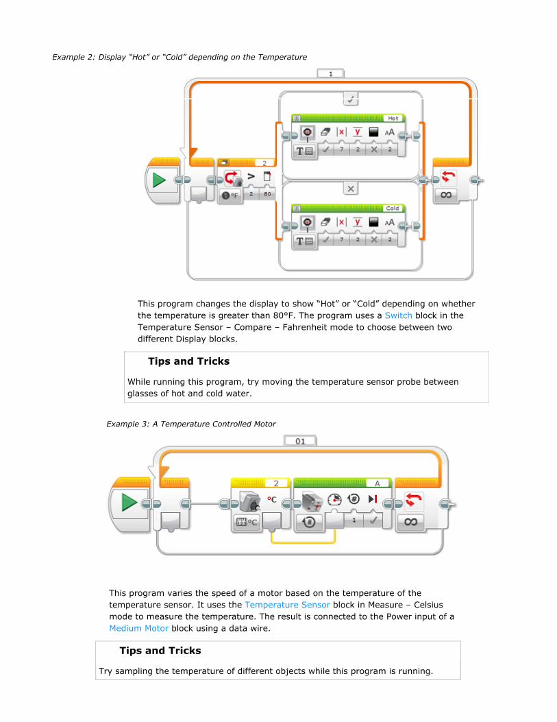
This program changes the display to show “Hot” or “Cold” depending on whetherthe temperature is greater than 80°F. The program uses a Switch block in theTemperature Sensor – Compare – Fahrenheit mode to choose between twodifferent Display blocks.
Tips and Tricks
While running this program, try moving the temperature sensor probe betweenglasses of hot and cold water.
Example 3: A Temperature Controlled Motor
This program varies the speed of a motor based on the temperature of thetemperature sensor. It uses the Temperature Sensor block in Measure – Celsiusmode to measure the temperature. The result is connected to the Power input of aMedium Motor block using a data wire.
Tips and Tricks
Try sampling the temperature of different objects while this program is running.
Example 2: Display “Hot” or “Cold” depending on the Temperature

Sensor -Compare
value.
Wait TemperatureSensor - Change
Wait for the temperature to change by acertain amount.
Loop TemperatureSensor
Repeat a sequence of blocks until thetemperature reaches a certain value.
Switch TemperatureSensor
Choose between two sequences of blocksbased on the temperature.
TemperatureSensor
Measure Measure the temperature, and get the resulton a Numeric data wire.
TemperatureSensor
Compare Compare the temperature to a threshold, andget the result on a Logic data wire.
DataLogging
See Data Logging.
TEMPERATURE SENSOR BLOCKS AND MODES
The table below shows all of the programming blocks and modes that you can use withthe Temperature Sensor.
Block Mode Use
Wait TemperatureSensor -
Wait for the temperature to reach a certainvalue.

Using the Energy MeterINDEX
Home
General
ToolsProgramming BlocksData Logging
Getting StartedProgramsProject PropertiesConnecting to EV3Hardware PagePort SelectionData WiresData TypesContent EditorTeacher ModeManaging FilesEV3 Keyboard ShortcutsSupported TextDaisy ChainingPrinting
Using SensorsInfrared (IR)IR Beacon ModeIR Proximity ModeIR Remote ModeUltrasonicColorTimerTouchBrick ButtonsMotor RotationGyroNXT SoundTemperatureEnergy Meter
The Energy Meter is part of the Renewable EnergyAdd-On Set. If you connect the Energy Meter to asensor port on the EV3 Brick, the meter can providedata about the electrical energy storage, input, andconsumption of the electrical components connected toit.
You could use the Energy Meter to program your ownautomated energy experiments. For example, youmight program a motor to run only when there isenough input power from a solar panel or enoughstored energy in the battery.
ENERGY METER DATA
The Energy Meter provides seven kinds of Numericdata:
Data Type Range Units Notes
InVoltage(V)
Numeric 0.0 to10.0
Volts(V)
Inputvoltage
InCurrent(A)
Numeric 0.0 to0.3
Amps(A)
Inputcurrent
InWattage(W)
Numeric 0.0 to3.0
Watts(W)
Inputpower
OutVoltage(V)
Numeric 0.0 to10.0
Volts(V)
Outputvoltage
OutCurrent(A)
Numeric 0.0 to0.5
Amps(A)
Outputcurrent
OutWattage(W)
Numeric 0.0 to5.0
Watts(W)
Outputpower
Joule(J)
Numeric 0 to100
Joules(J)
Storedenergy
See the documentation for the Renewable Energy Add-On Set for more information.
Energy Meter
Quick linksEnergy Meter DataBlocks that Can Use the Energy

Using the data from the Energy Meter in a program isvery similar to using data from other sensors that giveNumeric data. See, for example, Using the ColorSensor.
BLOCKS THAT CAN USE THE ENERGYMETER
The table below lists the different programming blocksthat can be used with the Energy Meter. Each blockwill have different modes for each of the seven kindsof data provided by the meter.
Block Mode Use
Wait EnergyMeter -Compare
Wait for a data reading toreach a certain value.
Wait EnergyMeter -Change
Wait for a data reading tochange by a certainamount.
Loop EnergyMeter
Repeat a sequence ofblocks until a data readingreaches a certain value.
Switch EnergyMeter
Choose between twosequences of blocks basedon a data reading.
EnergyMeter
Measure Get a data reading on aNumeric data wire.
EnergyMeter
Compare Compare a data reading toa threshold and get theresult on a Logic data wire.
DataLogging
See Data Logging