lego-pol: a 48v-1.5v 300a merged-two-stage hybrid
TRANSCRIPT

LEGO-PoL: A 48V-1.5V 300A Merged-Two-Stage HybridConverter for Ultra-High-Current Microprocessors
Jaeil Baek†, Ping Wang†, Youssef Elasser†, Yenan Chen†, Shuai Jiang‡, Minjie Chen††Princeton University, Princeton, NJ, United States‡Google, Mountain View, CA, United States
Email: †jaeil.baek, [email protected]; ‡[email protected]
Abstract—This paper presents a family of 48 V–1.5 V merged-two-stage hybrid-switched-capacitor converters with a LinearExtendable Group Operated Point-of-Load (LEGO-PoL) architec-ture for high current microprocessors. The proposed LEGO-PoL converter leverages the advantages of switched-capacitor(SC) circuits and multiphase buck circuits and can achievesoft charging, current sharing, and automatic voltage balancing.The SC circuits are connected in series to split the high inputvoltage into multiple stacked voltage domains, and the multiphasebuck circuits are connected in parallel to split the high outputcurrent into multiple parallel current paths. The inductors of themultiphase buck converters are used as current sources to soft-charge and soft-switch the switched-capacitor circuits, and theswitched-capacitor circuits are utilized to ensure current sharingamong the multiphase buck circuits. The voltage balancing andcurrent sharing mechanisms of the LEGO-PoL architecture areinvestigated in detail. A 450 W, 48 V–1.5 V, 300 A LEGO-PoLconverter with a peak efficiency of 96%, a full load efficiency of87.7%, and a power density of 577 W/in3 was built and testedto verify the effectiveness of the LEGO-PoL architecture.
Index Terms—DC-DC power conversion, hybrid switched-capacitor circuit, linear extendable group operated (LEGO)architecture, point of load (PoL) converter
I. INTRODUCTION
Power converters with high efficiency, high power den-sity, and high bandwidth are needed to support future highperformance microprocessors (CPUs, GPUs, and TPUs) [1]–[13]. One emerging trend in data center power delivery isto feed the servers with high voltage (e.g., 48 V) from theopen compute racks. Delivering power at 48V reduces theconduction loss, improves the UPS deployment flexibility, andcan leverage the existing semiconductor devices and circuittopologies of the 48 V telecom power ecosystems. Varioustopologies for high voltage conversion ratio high current PoLapplications have been proposed, including hybrid-switched-capacitor-based designs [1]–[8], multi-phase-buck designs [9],[10], and transformer-based designs [11]–[13].
Among these solutions, two-stage “switched-capacitor &multiphase buck” designs are very attractive as they seper-ate the challenges of achieving high conversion ratio andhigh bandwidth. Many recently proposed switched capacitorconverters can achieve unique advantages in uniform devicevoltage stress and current stress, and can obtain soft chargingand soft switching [1]–[10]. Resonant switched-capacitor cir-cuits requires resonant inductors and many switches to achievesoft-charging, soft-switching and high conversion ratio. The
switched-capacitor stage and the following buck stage areusually decoupled, limiting the system efficiency and powerdensity that can be achieved.
The recently proposed Linear Extendable Group OperatedPoint-of-Load (LEGO-PoL) architecture [5] fits particularlywell to high-conversion-ratio high-output-current PoL appli-cations. The LEGO-PoL architecture merges the operation ofthe switched capacitor stage and the multiphase buck stageand creates unique opportunities to improve the efficiency andpower density. It eliminates the resonant inductors and thedecoupling capacitors in hybrid-switched-capacitor circuits,and merges the operation of the switched-capacitor stageand the buck stage to create soft-charging and soft-switchingopportunities. It offers automatic voltage balancing and currentsharing, which are important for high-conversion-ratio, high-output-current applications. It leverages the high performanceof low voltage DrMOS devices and multiphase buck control.This paper systematically investigates the soft-charging, cur-rent sharing, and voltage balancing mechanisms of the LEGO-PoL architecture, and shows enhanced experimental resultswith a 450 W, 48 V-1.5 V, 300 A LEGO-PoL prototype whichachieves a peak efficiency of 96%, a full load efficiency of87.7%, and a power density of 577 W/in3.
II. PRINCIPLES OF THE LEGO-POL ARCHITECTURE
Fig. 1 shows one submodule of the LEGO-PoL architectureincluding a 2:1 switched-capacitor unit and a single-phasebuck unit. There is no dc-decoupling capacitor between thetwo units. Many 2:1 switched-capacitor units can be stacked inseries on the input side. They usually operate at a lower switch-ing frequency. Many buck units can be connected in parallelon the output side. They usually operate at a higher frequency.The inductors of the buck units charge and discharge thecapacitors of the switched-capacitor unit with soft-charging.The capacitors (CF1 & CF2) of the switched-capacitor unitare used as the input capacitors of the buck unit.
Fig. 2 shows the topology of an example LEGO-PoL con-verter with three series-stacked 2:1 switched-capacitor unitsand three parallel connected 4-phase buck units. The threeswitched-capacitor units convert 48 V to 8 V (3×2:1=6:1),and the three 4-phase buck units convert 8 V to 1.5 V andshare 300 A. The 8 V bus virtually exists and there is nodecoupling capacitor between the switched-capacitor unit and4-phase buck unit. Each of 4-phase buck units uses capacitors
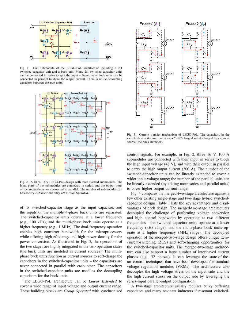
Fig. 1. One submodule of the LEGO-PoL architecture including a 2:1switched-capacitor unit and a buck unit. Many 2:1 switched-capacitor unitscan be connected in series to split the input voltage; many buck units can beconnected in parallel to share the output current. There is no dc-decouplingcapacitor between the two units.
Fig. 2. A 48 V-1.5 V LEGO-PoL design with three stacked submodules. Theinput ports of the submodules are connected in series, and the output portsof the submodules are connected in parallel. The number of submodules canbe Lineary Extended and they are Group Operated.
of its switched-capacitor stage as the input capacitor, andthe inputs of the multiple 4-phase buck units are separated.The switched-capacitor units operate at a lower frequency(e.g., 100 kHz), and the multi-phase buck units operate at ahigher frequency (e.g., 1 MHz). The dual-frequency operationenables high converter bandwidth for the microprocessorswhile offering high efficiency and high power density for thepower conversion. As illustrated in Fig. 3, the operations ofthe two stages are highly integrated in the two operation states(the buck units are modeled as current sources). The multi-phase buck units function as current sources to soft-charge thecapacitors in the switched-capacitor units – the capacitors arenever connected in parallel with each other. The capacitorsin the switched-capacitor units are used as the decouplingcapacitors for the buck units.
The LEGO-PoL architecture can be Linear Extended tocover a wide range of input voltage and output current range.These building blocks are Group Operated with synchronized
Fig. 3. Current transfer mechanism of LEGO-PoL. The capacitors in theswitched-capacitor units are always “soft” charged and discharged by a currentsource (the buck inductor).
control signals. For example, in Fig. 2, three 16 V, 100 Asubmodules are connected with their input in series to blockthe high input voltage (48 V), and with their output in parallelto carry the high output current (300 A). The number of theswitched-capacitor units can be linearly extended to cover awider input voltage range; the number of the parallel units canbe linearly extended (by adding more series and parallel units)to cover higher output current range.
Fig. 4 compares the merged-two-stage architecture against afew other existing single-stage and two-stage hybrid switched-capacitor designs. Table I lists the key advantages and disad-vantages of each design. The merged-two-stage architecturesdecoupled the challenge of performing voltage conversionand high control bandwidth by operating at two differentfrequencies - the switched-capacitor units operate at a lowerfrequency (kHz range), and the multi-phase buck units op-erate at a higher frequency (MHz range). The decoupledoperation of the merged-two-stage design offers unique zero-current-switching (ZCS) and soft-charging opportunities forthe switched-capacitor units. The merged-two-stage architec-ture can also support a large number of interleaved currentphases (e.g., 32 phases). It can leverage the state-of-the-art control techniques that have been developed for standardvoltage regulation modules (VRMs). The architecture alsodecouples the high voltage stress on the input side and thethe high current stress on the output side by leveraging theseries-input parallel-output configuration.
A two-stage architecture usually requires bulky bufferingcapacitors and many resonant inductors if resonant switched-
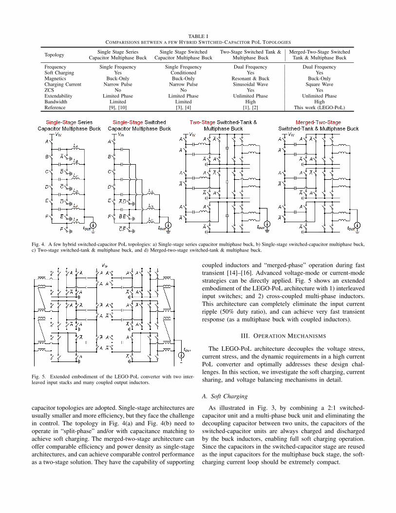
TABLE ICOMPARISIONS BETWEEN A FEW HYBRID SWITCHED-CAPACITOR POL TOPOLOGIES
Topology Single Stage SeriesCapacitor Multiphase Buck
Single Stage SwitchedCapacitor Multiphase Buck
Two-Stage Switched Tank &Multiphase Buck
Merged-Two-Stage SwitchedTank & Multiphase Buck
Frequency Single Frequency Single Frequency Dual Frequency Dual FrequencySoft Charging Yes Conditioned Yes YesMagnetics Buck-Only Buck-Only Resonant & Buck Buck-OnlyCharging Current Narrow Pulse Narrow Pulse Sinusoidal Wave Square WaveZCS No No Yes YesExtendability Limited Phase Limited Phase Unlimited Phase Unlimited PhaseBandwidth Limited Limited High HighReference [9], [10] [3], [4] [1], [2] This work (LEGO-PoL)
Fig. 4. A few hybrid switched-capacitor PoL topologies: a) Single-stage series capacitor multiphase buck, b) Single-stage switched-capacitor multiphase buck,c) Two-stage switched-tank & multiphase buck, and d) Merged-two-stage switched-tank & multiphase buck.
Fig. 5. Extended embodiment of the LEGO-PoL converter with two inter-leaved input stacks and many coupled output inductors.
capacitor topologies are adopted. Single-stage architectures areusually smaller and more efficiency, but they face the challengein control. The topology in Fig. 4(a) and Fig. 4(b) need tooperate in “split-phase” and/or with capacitance matching toachieve soft charging. The merged-two-stage architecture canoffer comparable efficiency and power density as single-stagearchitectures, and can achieve comparable control performanceas a two-stage solution. They have the capability of supporting
coupled inductors and “merged-phase” operation during fasttransient [14]–[16]. Advanced voltage-mode or current-modestrategies can be directly applied. Fig. 5 shows an extendedembodiment of the LEGO-PoL architecture with 1) interleavedinput switches; and 2) cross-coupled multi-phase inductors.This architecture can completely eliminate the input currentripple (50% duty ratio), and can achieve very fast transientresponse (as a multiphase buck with coupled inductors).
III. OPERATION MECHANISMS
The LEGO-PoL architecture decouples the voltage stress,current stress, and the dynamic requirements in a high currentPoL converter and optimally addresses these design chal-lenges. In this section, we investigate the soft charging, currentsharing, and voltage balancing mechanisms in detail.
A. Soft Charging
As illustrated in Fig. 3, by combining a 2:1 switched-capacitor unit and a multi-phase buck unit and eliminating thedecoupling capacitor between two units, the capacitors of theswitched-capacitor units are always charged and dischargedby the buck inductors, enabling full soft charging operation.Since the capacitors in the switched-capacitor stage are reusedas the input capacitors for the multiphase buck stage, the soft-charging current loop should be extremely compact.
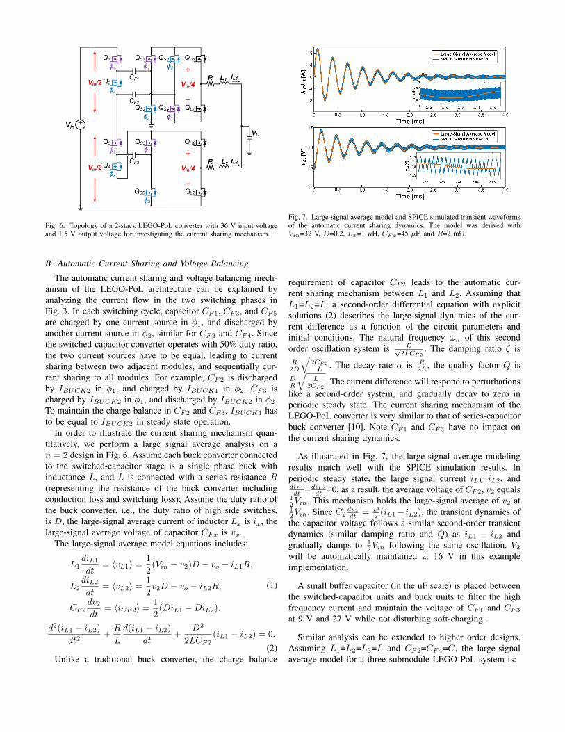
Fig. 6. Topology of a 2-stack LEGO-PoL converter with 36 V input voltageand 1.5 V output voltage for investigating the current sharing mechanism.
B. Automatic Current Sharing and Voltage Balancing
The automatic current sharing and voltage balancing mech-anism of the LEGO-PoL architecture can be explained byanalyzing the current flow in the two switching phases inFig. 3. In each switching cycle, capacitor CF1, CF3, and CF5
are charged by one current source in φ1, and discharged byanother current source in φ2, similar for CF2 and CF4. Sincethe switched-capacitor converter operates with 50% duty ratio,the two current sources have to be equal, leading to currentsharing between two adjacent modules, and sequentially cur-rent sharing to all modules. For example, CF2 is dischargedby IBUCK2 in φ1, and charged by IBUCK1 in φ2. CF3 ischarged by IBUCK2 in φ1, and discharged by IBUCK2 in φ2.To maintain the charge balance in CF2 and CF3, IBUCK1 hasto be equal to IBUCK2 in steady state operation.
In order to illustrate the current sharing mechanism quan-titatively, we perform a large signal average analysis on an = 2 design in Fig. 6. Assume each buck converter connectedto the switched-capacitor stage is a single phase buck withinductance L, and L is connected with a series resistance R(representing the resistance of the buck converter includingconduction loss and switching loss); Assume the duty ratio ofthe buck converter, i.e., the duty ratio of high side switches,is D, the large-signal average current of inductor Lx is ix, thelarge-signal average voltage of capacitor CFx is vx.
The large-signal average model equations includes:
L1diL1dt
= 〈vL1〉 =1
2(Vin − v2)D − vo − iL1R,
L2diL2dt
= 〈vL2〉 =1
2v2D − vo − iL2R,
CF2dv2dt
= 〈iCF2〉 =1
2(DiL1 −DiL2).
(1)
d2(iL1 − iL2)dt2
+R
L
d(iL1 − iL2)dt
+D2
2LCF2(iL1 − iL2) = 0.
(2)Unlike a traditional buck converter, the charge balance
Fig. 7. Large-signal average model and SPICE simulated transient waveformsof the automatic current sharing dynamics. The model was derived withVin=32 V, D=0.2, Lx=1 µH, CFx=45 µF, and R=2 mΩ.
requirement of capacitor CF2 leads to the automatic cur-rent sharing mechanism between L1 and L2. Assuming thatL1=L2=L, a second-order differential equation with explicitsolutions (2) describes the large-signal dynamics of the cur-rent difference as a function of the circuit parameters andinitial conditions. The natural frequency ωn of this secondorder oscillation system is D√
2LCF2. The damping ratio ζ is
R2D
√2CF2
L . The decay rate α is R2L , the quality factor Q is
DR
√L
2CF2. The current difference will respond to perturbations
like a second-order system, and gradually decay to zero inperiodic steady state. The current sharing mechanism of theLEGO-PoL converter is very similar to that of series-capacitorbuck converter [10]. Note CF1 and CF3 have no impact onthe current sharing dynamics.
As illustrated in Fig. 7, the large-signal average modelingresults match well with the SPICE simulation results. Inperiodic steady state, the large signal current iL1=iL2, anddiL1
dt =diL2
dt =0, as a result, the average voltage of CF2, v2 equals12Vin. This mechanism holds the large-signal average of v2 at12Vin. Since C2
dv2dt = D
2 (iL1− iL2), the transient dynamics ofthe capacitor voltage follows a similar second-order transientdynamics (similar damping ratio and Q) as iL1 − iL2 andgradually damps to 1
2Vin following the same oscillation. V2will be automatically maintained at 16 V in this exampleimplementation.
A small buffer capacitor (in the nF scale) is placed betweenthe switched-capacitor units and buck units to filter the highfrequency current and maintain the voltage of CF1 and CF3
at 9 V and 27 V while not disturbing soft-charging.
Similar analysis can be extended to higher order designs.Assuming L1=L2=L3=L and CF2=CF4=C, the large-signalaverage model for a three submodule LEGO-PoL system is:

X +R
LX +
D2
4LCMX = 0,
X =
d2iL1
dt2
d2iL2
dt2
d2iL3
dt2
, X =
diL1
dt
diL2
dt
diL3
dt
, X =
iL1
iL2
iL3
,
M =
1 −1 0−1 2 −10 −1 1
,
Q =
−0.577 −0.707 0.408−0.577 0 −0.816−0.577 0.707 0.408
, Λ =
0 0 00 1 00 0 3
.
(3)
Note M is a real symmetric matrix. M can be diagonalizedas M=QΛQ−1 where Q is a matrix composed of eigenvectors(e1, e2, and e3), and Λ is a diagonal matrix composed ofeigenvalues (λ1, λ2, and λ3) of M respectively. (3) can berewritten as (4) by denoting Y=Q−1X.
Y +R
LY +
D2
4LCΛY,
d2y1dt2
=R
L
dy1dt
+D2
4LC(λ1y1) = 0,
d2y2dt2
=R
L
dy2dt
+D2
4LC(λ2y2) = 0,
d2y3dt2
=R
L
dy3dt
+D2
4LC(λ3y3) = 0.
(4)
Since iL1 − iL3 is the same with y2, the second-orderdifferential equation of (iL1 − iL3) is:
d2(iL1 − iL3)dt2
+R
L
d(iL1 − iL3)dt
+D2
4LC(iL1−iL3) = 0. (5)
This second-order differential equation describes the large-signal dynamics of the current difference in the three submod-ule design. The current difference gradually damps to zero inperiodic steady state. For this reason, the average voltages ofCF2 and CF4, v2 and v4, reach 2Vin
3 and Vin3 respectively.
As illustrated in Fig. 8, this large-signal average model alsomatches well with SPICE simulation results. The capacitanceCF1, CF3, and CF5 have no impact on the current sharing andvoltage balancing. A generalized large signal average modelof the LEGO-PoL architecture with arbitrary N submodulesis provided in the Appendix. As proved in the Appendix,automatic current sharing and automatic voltage balancing areguaranteed in a LEGO-PoL architecture with N submodules.
IV. DESIGN CONSIDERATIONS
A. Switches of the Switched-Capacitor Stage
The series stacked 2:1 switched-capacitor units split the in-put voltage into small voltage domains. As a result, the LEGO-PoL converter can use low voltage rating devices with lowon-resistance. The voltage ratings of the active switches are
Fig. 8. Large-signal average model and SPICE simulated transient responseof the automatic current sharing dynamics for n = 3 design. The model wasderived with Vin=48 V, D=0.2, Lx=1 µH, CFx=45 µF, and R=2 mΩ.
either VBUS or 2VBUS . Unlike a traditional two-stage hybrid-switched-capacitor designs, the voltages across all switchesare clamped by the capacitors under all worst case situations.The merged two-stage operation enables switches to operate atlower switching frequency with zero-current-switching (ZCS).For this reason, the switches in the switched-capacitor stagehave reduced switching loss compared to other switched-capacitor implementations.
B. Capacitors of the Switched-Capacitor Stage
In many hybrid-switched-capacitor designs, the capacitorsneed to be carefully selected because the capacitance valuedetermines the soft charging, soft-switching and resonant op-eration. The LEGO-PoL converter eliminates the resonant in-ductors in traditional resonant-switched-capacitor designs andachieves soft charging operation by using the buck inductors ascurrent sources. Smaller capacitance values with larger voltageripple are allowed. The capacitance value does not need to beprecised controlled. This allows a variety of capacitors to beused in a LEGO-PoL design. Class-II (e.g., X5R, X5S, X6S,X7R, etc.) MLCC capacitors can be freely considered withhigh tolerance to dc voltage bias, temperature variation, andcapacitance degradation.
C. Design of the Multiphase Buck Stage
The buck stage of the LEGO-PoL converter can follow thedesign considerations of the state-of-the-art standard VRMsusing multiphase buck converters. The multiphase buck con-verters can be interleaved with their inductors coupled witheach other. Advanced control techniques are directly appli-cable. Current sharing is guaranteed across the multiphasebuck units belonging to different submodules. For example,in Fig. 2, the LEGO-PoL controller only needs to balance thecurrent of each four-phase buck unit in a 12-phase interleavedoperation. In a traditional 12-phase buck converter, the con-troller needs to balance the current of all 12 phases.

TABLE IICOMPONENTS LIST OF THE 48 V-1.5 V, 300 A LEGO-POL CONVERTER
Q1 & Q6 BSZ013N2LS (25V, 1.3mΩ)Q2 - Q5 BSZ0501NSI (30V, 2.0mΩ)
QS1 - QS10 BSZ013N2LS (25V, 1.3mΩ)CF1 - CF5 45µF, 1210, X7R, MurataQH& QL SiC632 (DrMOS, 24V, 50A)L1 - L12 1.0µH (HC1-1R0-R, 1.23mΩ)
Digital Controller TMS320F28069
Fig. 9. Picture of the 48 V-1.5 V/300 A LEGO PoL prototype with threeseries stacked submodules and twelve interleaved buck phases.
D. PCB Layout Principles
Eliminating the decoupling capacitor between two stagescreates the soft-charging and soft switching opportunities, butbrings challenges in printed circuit board layout and design.The capacitors of the switched-capacitor units are reused asthe input capacitors of the buck units. As a result, the highfrequency current loop between the switched-capacitor unitsand the buck units should be as small as possible.
V. EXPERIMENTAL RESULTS
To verify the effectiveness of the LEGO-PoL architecture,a 40 V-60 V input (48 V nominal) and 1.5 V, 300 A outputis built and tested. Fig. 9 shows a picture of the prototype.The circuit topology is shown in Fig. 2. Three 2:1 switched-capacitor stages were stacked in series on the input side (48
Fig. 10. Picture of the experimental platform including the 48 V/1.5 V 300A prototype, a few voltage/current meters and a few electronic loads.
(a)
(b)
Fig. 11. Measured efficiency of the 48 V-1.5 V 300 A LEGO-PoL systemat different operating frequencies: (a) Fix the switched-capacitor frequencyat 125 kHz, and sweep the buck frequency; (b) Fix the buck frequency at500 kHz, and sweep the switched-capacitor frequency.
V), and three 4-phase buck units were connected in parallelon the output side (1.5 V, 300 A). Table II lists the bill-of-material (BOM) of this design. The switches in the switched-capacitor units are implemented as standard MOSFETs. Theswitches in the multi-phase buck units are implemented aslow voltage DrMOS. CF1-CF5 are 45 µF. In a traditionaltwo-stage design with similar performance, the capacitor size

(a) (b)
Fig. 12. Measured waveforms during a step change of the switched-capacitorfrequency: (a) From 83.5 kHz to 125 kHz; (b) From 125 kHz to 250 kHz.The buck frequency was fixed at 500 kHz.
(a) (b)
Fig. 13. Measured waveforms during a load step transient (from 100 A↔150A). (a) Voltages of the switch node in the switched-capacitor units (vA, vB ,vC ); (b) Input voltage (Vin), bus voltage (VBUS ), and output voltage (VO).
would be 150 µF. 500 nF 0603 size capacitors are used as inputcapacitors of the DrMOS. The buck inductor is 1 µH. Thepower density of the prototype (considering the power stage)is 577 W/in3. Fig. 10 shows a picture of the experimentalplatform. We connected two Chroma 63103A in parallel asthe electronic load. Agilent 34401 and 34330A current shuntwere used for measuring efficiency. A Tektronix current probe(TCP404XL & TCPA400) was used to measure the transientof the current waveform.
Fig. 11 shows the measured efficiency of the 48 V–1.5 V300 A LEGO-PoL system. The buck stage and the switchedcapacitor stage are operating at different frequencies. The peakefficiency of the 48 V-1.5 V system is 95.75% at 40 A,and 85% at 300 A with fBuck=500 kHz, and fSC=125 kHz.If CF was increased to 90 µF, the system peak efficiencyand full load efficiency were increased to 96% and 87.7%.respectively. In a traditional hybrid-switched-capacitor design,the switching frequency usually needs to be fixed to maintainresonant operation and maintain soft switching. By modulatingthe switching frequency, the LEGO-PoL converter can achievehigher performance across a wide operation range. The powerdensity of the prototype is 577 W/in3 (power stage only).Fig. 12 shows the transient waveforms when the switched-capacitor operating frequency changes. As the switching fre-quency increases, the ripples in the bus voltage are reduced.The average value of bus voltage and output voltage are wellmaintained, and the capacitor voltages are well balanced.
Fig. 13 shows the transient response of the prototype whenthe load steps between 100 A and 150 A. The voltages ofthe switch node in the switched-capacitor units (vA, vB , andvC) maintains the same during transient, indicating automatic
current sharing and voltage balancing. The intermediate busvoltage (VBUS) and output voltage (VO) are also well regulatedduring the load step change.
VI. CONCLUSIONS
This paper presents a family of LEGO-PoL converters withmerged-two-stage operation for very high current micropro-cessors. By merging the operation of the switched-capacitorunits and the multi-phase buck units, a LEGO-PoL convertercan achieve soft charging and ZCS operation without resonantinductors. The merged-two-stage operation also enables highcontrol bandwidth for voltage regulation while offering highefficiency and high power density. The LEGO-PoL systemcan be linearly extended by adding more switched-capacitoror multiphase buck building blocks with automatic voltagebalancing and current sharing. A 48 V-1.5 V 300 A CPU powersupply has been built and tested to verify the effectivenessof the LEGO-PoL architecture. The peak efficiency of theprototype is 96%. The full load efficiency of the system is87.7%. The power density of the prototype is 577 W/in3.
ACKNOWLEDGMENT
The authors would like to thank the National ScienceFoundation (Award #1847365) and Princeton University SEASInnovation Fund for supporting this work.
APPENDIX
This appendix investigates the current sharing and voltagebalancing mechanisms of the LEGO-PoL architecture with Nsubmoudles. Assuming that L1 = L2 = · · · = LN = L,and CF2 = CF4 = · · · = CF (2(N−1)) = C, the large-signalaverage model of the system is:
X +R
LX +
D2
4LCMX = 0,
X =
d2iL1
dt2
d2iL2
dt2
...
d2iLNdt2
, X =
diL1
dt
diL2
dt
...diLNdt
, X =
iL1
iL2
...
iLN
,
M =
1 −1 0 0 · · · 0−1 2 −1 0 · · · 00 −1 2 −1 · · · 0...
......
. . . · · ·...
0 0 · · · −1 2 −10 0 · · · 0 −1 1
.
(6)
xT ·M · x =
N−1∑k=1
(xk+1 − xk)2 ≥ 0 (7)
M is a N×N real symmetric matrix, so it can be diagonalizedas M = QΛQ−1, where Q = [e1, e2, · · ·, eN ] and Λ is thediagonal matrix consisting of eigenvalues (λ1, λ2, · · · , λN ).

For any non-zero x=[x1, x2, · · · , xN ]T , M satisfies (7), so Mis positive semidefinite, i.e. λk ≥ 0 (k = 1, 2, · · · , N). Therank of M is N − 1, so there exists and only exists one zeroeigenvalue. Assuming λ1 = 0, and the corresponding e1 canbe found as [1, 1, ..., 1]T . Denoting Y=Q−1X, then (6) can berewritten as (8) with explicit solutions:
d2y1dt2 + R
Ldy1dt = 0, k = 1,
d2ykdt2 + R
Ldykdt + ( D
2
4LCλk)yk = 0, k = 2, 3, · · · , N(8)
The general solutions for (8) are: y1(t) = K11e(−αt) +K12,
yk(k≥2)(t) = Kk1e−α+√α2−4β2
k2 t +Kk2e
−α−√α2−4β2
k2 t,
(9)where Kk1 and Kk2 are constant coefficients, α = R
L , andβk = D2λk
4LC . Since α is larger than zero, y1(t) damps toK12, and yk(k≥2)(t) damps to zero as time goes to infinity.When there are repeated roots for the characteristic equation,yk(k≥2)(t) have similar form as (9) and also damp to zero astime goes to infinity. Therefore, in periodic steady state, thelarge signal inductor currents of the LEGO-PoL architecturewith N submodules settle to the same constant value K12:
iL1iL2
...iLN
= Q−1Y = [e1, e2, · · ·, eN ]
K12
0...0
=
K12
K12
...K12
.(10)
Similarly, the average capacitor voltages of VCF2,VCF4, · · · , VCF (2(N−1) damp to a balanced voltage:
VCF2
VCF4
...VCF (2(N−1))
=VinN
N − 1N − 2
...1
. (11)
Fig. 14 shows the SPICE verification of the dynamic modelof a n = 7 design. The charge balancing mechanism of thecapacitors maintains the current sharing and voltage balanc-ing for the LEGO-PoL architecture with a large number ofmodular building blocks.
REFERENCES
[1] S. Jiang, S. Saggini, C. Nan, X. Li, C. Chung and M. Yazdani, “SwitchedTank Converters,” IEEE Transactions on Power Electronics, vol. 34, no.6, pp. 5048-5062, June 2019.
[2] Y. Li, X. Lyu, D. Cao, S. Jiang and C. Nan, “A 98.55% EfficiencySwitched-Tank Converter for Data Center Application,” IEEE Transac-tions on Industry Applications, vol. 54, no. 6, pp. 6205-6222, Jun. 2018.
[3] R. C. N. Pilawa-Podgurski, D. M. Giuliano and D. J. Perreault, “Mergedtwo-stage power converter architecture with soft charging switched-capacitor energy transfer,” IEEE Power Electronics Specialists Confer-ence, Rhodes, 2008.
[4] T. Xie, R. Das, G. Seo, D. Maksimovic and H. Le, “Multiphase Controlfor Robust and Complete Soft-charging Operation of Dual InductorHybrid Converter,” IEEE Applied Power Electronics Conference andExposition (APEC), Anaheim, CA, USA, 2019, pp. 1-5.
Fig. 14. SPICE verification of the dynamic model for a n = 7 design. Themodel was derived with Vin=112 V, D=0.2, Lx=1 µH, CFx=45 µF, andR=2 mΩ. The deviation of the capacitor voltages VCF2, VCF4, · · · , VCF12
from balanced values are −1V,+2V,−3V, · · · ,+6V . The derived modelmatches very well with simulation results.
[5] J. Baek, P. Wang, S. Jiang and M. Chen, “LEGO-PoL: A 93.1% 54V-1.5V 300A Merged-Two-Stage Hybrid Converter with a Linear Extend-able Group Operated Point-of-Load (LEGO-PoL) Architecture,” IEEEWorkshop on Control and Modeling of Power Electronics (COMPEL),Toronto, ON, 2019.
[6] P. H. McLaughlin, P. A. Kyaw, M. H. Kiani, C. R. Sullivan and J.T. Stauth, “Two-Phase Interleaved Resonant Switched-Capacitor DC-DCConverter with Coupled Inductors and Custom LC Resonator,” IEEEApplied Power Electronics Conference and Exposition (APEC), Anaheim,CA, USA, 2019, pp. 37-44.
[7] Z, Ye, Y. Lei and R. C. N. Pilawa-Podgurski, “A 48-to-12 V CascadedResonant Switched-Capacitor Converter for Data Center with 99% PeakEfficiency and 2500 W/in3 Power Density,” IEEE Applied Power Elec-tronics Conference and Exposition (APEC), Anaheim, CA, USA, 2019,pp. 13-18.
[8] J. Zhu and D. Maksimovic, “A Family of Transformerless Stacked ActiveBridge Converters,” IEEE Applied Power Electronics Conference andExposition (APEC), Anaheim, CA, USA, 2019, pp. 19-24.
[9] K. Nishijima, K. Harada, T. Nakano, T. Nabeshima and T. Sato, “Analysisof Double Step-Down Two-Phase Buck Converter for VRM,” Interna-tional Telecommunications Conference (INTELEC), Berlin, 2005, pp. 497-502.
[10] P. S. Shenoy et al., “A 5 MHz, 12 V, 10 A, monolithically integrated two-phase series capacitor buck converter,” IEEE Applied Power ElectronicsConference and Exposition (APEC), Long Beach, CA, 2016, pp. 66-72.
[11] C. Fei, M. H. Ahmed, F. C. Lee and Q. Li, “Two-Stage 48 V-12 V/6V-1.8 V Voltage Regulator Module With Dynamic Bus Voltage Controlfor Light-Load Efficiency Improvement,” IEEE Transactions on PowerElectronics, vol. 32, no. 7, pp. 5628-5636, July 2019.
[12] M. H. Ahmed, C. Fei, F. C. Lee and Q. Li, “High-Efficiency High-Power-Density 48/1V Sigma Converter Voltage Regulator Module,” IEEEApplied Power Electronics Conference and Exposition (APEC), Tampa,FL, 2017.
[13] M. H. Ahmed, C. Fei, F. C. Lee and Q. Li, “48-V Voltage RegulatorModule With PCB Winding Matrix Transformer for Future Data Centers,”IEEE Transactions on Industrial Electronics, vol. 64, no. 12, pp. 9302-9310, Dec. 2017.
[14] P. Wong, P. Xu, P. Yang and F.C. Lee, “Performance improvements ofinterleaving VRMs with coupling
[15] J. Li, A. Stratakos, A. Schultz and C. R. Sullivan, “Using Coupled Induc-tors to Enhance Transient Performance of Multi-Phase Buck Converters,”IEEE Applied Power Electronics Conference and Exposition (APEC),Anaheim, CA, USA, 2004, pp. 1289-1293.
[16] M. Xu, J. Zhou, K. Yao and F. C. Lee, “Small Signal Modeling ofa High Bandwidth Voltage Regulator Using Coupled Inductors,” IEEETransactions on Power Electronics, vol. 22, no. 2, pp. 399-406, Mar.2007.