lehigh university librariesdigital.lib.lehigh.edu/fritz/pdf/288_19.pdfsynopsis this report is based...
TRANSCRIPT

by
ichard J. Christopher
John • Fisher
Long Bolted Connections
F LL TEL L
~-,--~,--"----~--------~~,~--,_..~--------~--' - --- ---
/ LEHIGH UNIVERSITY LIBRARIES
. . 11111/11 /I 11111111111111111111111l1li11111/1 111111111111111111/ 1: 3 9151 00897607 4
- ------ -, ---- ---~
1.
2.
3.
TABLE OF CONTENTS
SYNOPSIS
INTRODUCTION
1.1 Purpose
1.2 Test Program
TEST PREPARATION AND PROCEDURE
2.1 Preparation of Bolts
2.2 Testing Equipment
2.3 Coupon and Hardness Testing Procedures
2.4 Direct Tension Testing Procedure
2.5 Torqued Tension Testing Procedure
2.6 Te~ting Procedure - Special Tests
RESULTS AND ANALYSIS
3.1 Coupon and Hardness Tests
3.2 Direct Tension Tests
3.3 Torqued Tension Tests
3.4 Combined Torqued-Direct Tension Tests
3.5 Repeated Wrench Installation
3.6 Bolts Installed in Steel Plate
3.7 Continuously Torqued Bolts
Page
1
2
2
3
6
6
6
7
8
9
10
13
13
14
17
22
23
24
27

SUM:MARY
ACKNOWLEDGEMENTS
TABLES AND FIGURES
REFERENCES
Page
28
31
33
49

SYNOPSIS
This report is based on results of tests of a large sample
of A354 and A490 bolts studied to determine their tensile behavior
when used as structural fasteners. Variables included bolt diameter,
grip length, thread length under nut, and thread lubrication. Bolts
were tested under various loadings to determine their behavior under
conditions often encountered in the field. When correctly used, these
bolts are satisfactory structural fasteners.
-1-

1. INTRODUCTION
1.1 PURPOSE
The prime objective of this study is,the investigation of
the performance of the alloy steel structural bolt when subjected to
various conditions of installation and load. A knowledge of this be
havior is required for the intelligent use of this bolt as a structural
fastener.
Knowledge of the tensile behavior of a bolt is important
for several reasons. First of all, this behavior affects installa
tion practices and methods of inspection. Secondly, in a joint de
signed to resist forces with bolt tension, information is needed to
predict the deformation and load capacities of the connection. Fin
ally, in a friction-type joint the available frictional resistance
before the joint slips into bearing is directly controlled by the ten
sile forces in the bolts. For these reason~ relationships must be
established to predict the tensile behavior of a bolt loaded by either
a direct axial force or by a combination of the two.
In addition to the basic tensile behavior, several other
problems deserve attention. How will an alloy steel bolt installed
with a wrench react to directly applied tensile forces? How often
can these bolts be reinstalled? Is the relationship between nut rota
tion and bolt load significantly affected when the bolt is wrench
tightened in an actual joint rather than in a hydraulic load cell?
-2-

Do these bolts react any differently when tightened continuously to a
given -nut rotation than they do when tightened incrementally, as most
experimenta~ procedures require? These problems will be discussed in'
this report.
The various methods of relating internal bolt tension to a
readily observed quantity such as torque, elongation, strain in the
shank of the bolt, load cell output, and turn-of-nut are discussed in
Ref. 1, which also presents a list of studies of A325 bolts. Several
recent investigations of alloy steel bolts were reported in Refs. 2
and 3'. ~reliminary results of the present study were first reported
in Ref. 4.
1.2 TEST PROGRAM
The test program included the study of the tensile behavior
of eight lots of bolts conforming to ASTM A354-58T, grades Be and BD(5),
and eight lots conforming to the A490(6) specification for quenched and
tempered alloy steel structural bolts. The A490 specification calls
for the heavy head and short thread length of A325(7) specification
together with chemical and physical properties nearly identical to
the A354 grade BD bolt. Bolt lots AD, BD, CD, and DD were made to
conform to the A490 specification by re-heat treating Canadian bolts
manufactured to AISI specification 4140.
Both 7/8 and I in. heavy and regular semi-finished hexagon
head bolts were tested. ASTM A194(8) grade 2H nuts with heavy semi-
-3-

finished hexagon heads were used with all bolts tested and hardened
washers were used under all nuts. All reference to bolt head and
nut size is that defined in the American Standards Association speci
fication B18.2(9).
Table 1 gives a complete description of the test specimens,
including such variables as length under head (L), grip length (g),
thread length under nut (t), diameter, head Size, and type of thread.
Each lot of bolts is identified by two letters followed by a series of
numbers and letters. The first number following the double letters
indicates the bolt diameter in eighths of an inch. The next number
or numbers indicates the length of thread under the nut in sixteenths
of an inc~. Finally, the letter S or L at the end of the designation
differentiates between ~hort (appro~. 4 in.) and long' (~pprox. 8 in.)
grip lengths. For example, the designation AC-7-9S indicates a 7/8 in.
diameter bolt with 9/16 in. thread under the nut and a short grip
length.
Since these tests were initiated to aid in the development
of the A490 bolt specification and since the A354 bolt was not· yet in
general use as a structural fastener, all of the bolts used for this
study were specially manufactured and therefore, exhibited a greater
variation in properties, both geometric and structural, than would
ordinarily be expected. Special attention was given to the resulting
problems, which included sub-standard th'read fit for some lots, a
wide scatter of individual test results, and a complete lack of shipp-
-4-

ing oil on the A354 Be grade bolts.
The overall test program was planned to investigate the
previously discussed major and secondary types of tensile behavior
of these bolts. Bolt coupon and hardness tests were conducted to
establish trends based on the phys~cal properties specified by ASTM.
Table 2 lists in condensed form the physical properties specified by
ASTM for the 7/8 and 1 in. bolts. In addition to the properties called
for in the A354 and the A490 specifications, the corresponding values
from the A325 specification are listed for comparison.
In planning the program, emphasis was placed on the deter
mination of basic tensile behavior in both direct and torque-induced
tension. Torqued tension tests of the A354 Be bolts could not be
completed until the threads were covered with a light, water-soluble
shipping oil. These bolts were received without any trace of lubrica
tion and before this oil was applied, threads seized at applied loads
as low as ten kips. Because of this behavior, a complete series of
torqued tension tests was conducted with a heavy multi-purpose" grease
type lubricant applied to the threads of both nuts and bolts, to
observe the effect of a lubricant heavier than shipping oil.
In addition to these basic ~ests, several special tests
were conducted without heavy lubricant to investigate the problems
discussed earlier.
-5-

2. TEST PREPARATION AND PROCEDURE
2 • 1 PREPARATION OF BOLTS
Before testing, all bolts were stamped with their lot
designations and with a number to identify them within their lot.
Holes were then drilled with a combination drill and countersink
in the center of each end of the bolt. These holes provided rings
6f contact for the tips of the C-frame extensometer at the inter
face of the drilled and the countersunk portions. This type of
contact was protected from damage and gave consistent readings in
sensitive to minor inclusions of dirt. Reference 1 gives a more de
tailed description of this preparation.
Each bolt was checked for thread fit with the'NC2A "Go" and
"No-Go" ring gages, and each nut was similarly checked with the .NC2B
plug gages. Only those bolts and nuts with proper thread fit were
used in the testing program.
2.2 TESTING EQUIPMENT
Bolt coupons were tested in a 60 kip universal testing
machine, using threaded tension grips to hold the coupons and a
Peters extensometer or autographic recorder to measure their elonga
tion.
A 300 kip universal testing machine was used for the direct
tension tests of full size bolts with special tension grips to hold
-6-

the bolt under head and nut.
Two different hydraulic bolt calibrators were used to measure
bolt tension during th~ torqued tension tests. One with a capacity of .
100 kips was used for the tests of 7/8 in. boits(lO)~ It was co~led
to an oil pump to test the bolts' in combined torqued-then-direct ten
sion. The other, with a tensile capacity of 220 kips and a better
resistance to torque, was used for all torqued tension tests of 1 in.
bolts.
All bolt elongations were measured with a C-frame extensometer
consisting of a rigid adjustable steel frame and an Ames dial with divi
sions of 0.0001 ,in. A counterweight was connected to the upper arm of
the frame so that it balanced in the measuring position.
The wrench used for all torqued tension tests was a large
capacity pneumatic impact wrench running on a line pressure of approxi-
mately 130 psi at the wrench. The wrench capacity was adequate for all
bolts tested.
Additional details of the tes.ting equipment are given in
Ref. 1. Also, photographs of the testing devices are shown.
2.3 COUPON AND HARDNESS TESTING PROCEDURES
Coupon and hardness tests were conducted according to the
applicable testing procedure specified in ASTM Designation A370(11).
Coupons of 0.505 in. in diameter were prepared and tested at an indi
cated strain rate of approximately 0.02 inches per minute. A complete
-7-

stress-strain curve was obtained for each coupon. Particular emphasis
was placed on ultimate tensile strength, final elongation, and final
reduction in area. Either an autographic recorder or a Peters gage
was used to measure elongations in the elastic and initial plastic
range, and a steel scale and dividers were used for the remainder of
the test. The final cross sectional area at the fracture was determined
by using a micrometer to measure two mutually perpendicular diameters
and using the mean value to calculate the equivalent circular area.
Hardness tests were conducted on the sides of the bolt head.
A belt grinder was used to remove all scale from the areas to be tested
and to obtain a smoothly polished surface. Heat input was kept to a
minimum by using water during the grinding operation. Standard Brinell
and Rockwell C hardness tests were then conducted. Two trials were made
on each bolt for each type of hardness test and at least two bolts from
each lot were tested.
2.4 DIRECT TENSION TESTING PROCEDURE
Each bolt was installed in the tension grips of the hydraulic
testing machine with the nut in the desired position. The initial bolt
length was then measured with the C-frame extensometer with no load on
the bolt. With the extensometer still in 'place, the bolt was loaded to
its specified proof load. The load was then removed and the length was
again measured to determine if permanent set had occurred. If the per
manent set exceeded 0.0005 in., the bolt was rejected as not meeting the
specification. Of the 84 bolts tested in direct tension only three were
-8-

rejected on this basis, and two of these were' later found to have
microscopic -cracks through· their shanks at the base of the head so
that their effective area at that point was only one half of the
shank area.
After the bolt was checked in this manner it was again
loaded, this time to failure. Load was applied at a rate of approxi
mately 0.01 in. total elongation per minute. Loads and elQngations
were measured at 10 kip intervals in the inelastic range until ulti
mate load was reached. Then, after one or two more readings, the
extensometer was removed and the bolt was allowed to fail at the same
rate of elongation. During the inelastic range of the test,the machine
was stopped one or more times to determine the static load level. This
was consistently found to be about one kip below that at testing speed.
The same reduction was noted in Ref. 1 for tests of A325 bolts.
After failure, the bolt was fitted together as well as poss
ible and the final measurement of elongation was made with the C-frame
extensometer or ,with a steel scale with .01 in. divisions.
2.5 TORQUED TENSION TESTING PROCEDURE
After the initial -length was measured, the bolt was installed
in the bolt calibrator with the proper thread length under the' nut.
This adjustment was obtained by using heavy packing washers to vary
the gripped length. These washers had milled surfaces which proVided
a tight fit between adjacent washers and the bearing plate of the bolt
calibrator.
-9-

The bolt was first tightened with a hand wrench to a "snug"
load of 8 kips (10 kips for the LI, AB, and JJ lots). The nut was
o .then turned with the impact wrench in 45 (1/8-turn) increments until
failure. Tightening was stopped at each increment and load and elonga
tion.readings were· taken. After failure, the final 'elongation was, mea-
sured, in most cases with a steel scale, and type.?f -failure was re~
cor~ed. This general procedure'was followed for all tests in which
wrench tightening was used.
2.q TESTING PROCEDURE - SPECIAL TESTS
The tes,ts of bolts loaded in direct tension after being pre-
loaded by a given ,nut rotation with an impact wrench were all conducted
in the small bolt calibrator because it was the only one which was
adapted to the oil pump. Because of this, the tests were limited to
7/8 in. bolts. The bolts were first loaded exactly ~s described above
for torqued tensio~ tests until 5/8 turn-af-nut was reached. Then the
oil pump was brought up to a pressure equivalent to that in the load
cell for the holt tension indicated. The valve between load cell and,
pump was then opened and the load was allowed to stabilize. The result-
ing change in load was never more than ±l kip. The extensometer was
then placed on the bolt and the bolt was loaded directly with the oil
pump without further nut rotation. Loads and elongations were measured
at small intervals until several readings had been taken_beyond the
ultimate load. Fin~lly the extensometer was removed and pumping con-
-10-

tinued' until bolt failure. Final elongation was measured with th~
extensometer and the type 0-£ fai lure was recorded.
The testing procedure for repeated wrench installation of
bolts was the same as that of the regular torqued tension tests
except that after a specified nut rotation, the nut was loosened
until all load was removed. This procedu~e was repeated' until bolt
failure. Final load, elongation, and number of cycles to failure
were than recorded. These tests were conducted to determine the
effects of reinstallation of alloy steel holts in the field. Heavy
thread lubricant was not used for these tests.
Several bolts were installed in steel plates and bolt load
could not be recorded during these tests. The bolts were installed
in the steel plate to the elongation, corresponding to "snug" load of
th~_~egular torqued tension tests. Then they were loaded to failure
in 45° increments. Elongation was measured at each increment. The
LI bolts were tested in a 4 in. square block of A440 steel with a
15/16 in. hole through it. The ED bolts were tested in four lin.
plies of A440 steel haVing the same overall dimensions as above.
All remaining lots were tested in the bolt calibrators with all oil
removed and the cylinder bearing against the casing of the cell.
Packing washers were used to provide the proper grip. The last
method, by far the easiest of the three, gave results consistent
with those of the first two methods. Again, in these tests the threads-
were lubricated only with shipping oil.
-11-

A number of bolts were continuously torqued to a specified
nut rotation for comparison with holts torqued by incremental nut
rotation. They were first snugged with a hand wrench and then
tightened with the impact wrench in the bolt calibrator; and when
the specified nut rotation was reached, the load and elongation were
recorded.
-12-

3. RESULTS AND ANALYSIS
3.1 COUPON AND HARDNESS TESTS
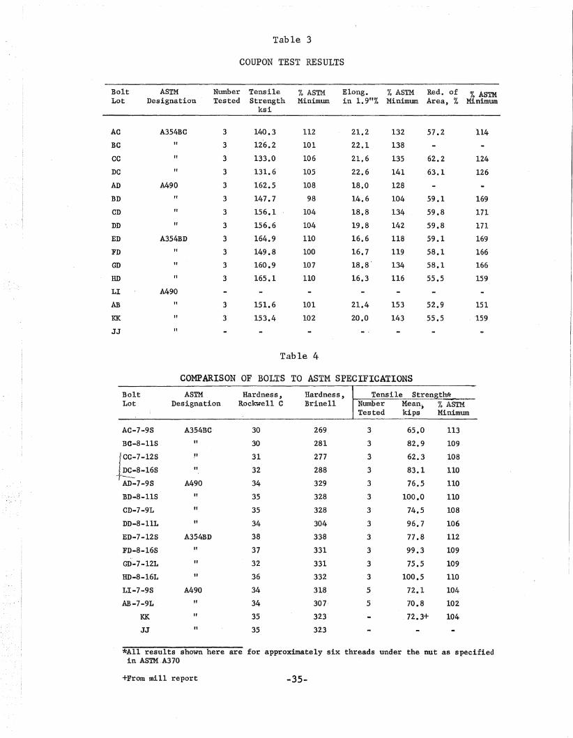
The results of all bolt coupon tests are listed in Table 3
and compared to minimum values specified by ASTM. All values for
strength and ductility exceeded specified minimum values except the
tensile strength for lot BD which was 98% 0'£ the specified value.
The elongations listed are for a gage length of 1.9 in. rather than
the two in. specified by ASTM. However, these values exceed the
specified values by a large margin except for the BD lot. Figure I
shows a typical stress-strain curve for a coupon cut from lot KK of
A490 bolts.
Table 4 lists the results of the Brinell and Rockwell C
har~ness tests for each bolt lot. These values all fall within the
range specified in the applicable ASTM specifications. This table
also gives the tensile strength for each lot of holts. Tensile
strength is discussed in more detail in the next section. It is
mentioned here only to point out that there is no good correlation
between the higher hardnesses and the higher tensile strengths re
ported; and the hardness values do not compare consistently with
each other. However, the results do serve their intended purpose in
checking that the bolts met ASTM specifications.
-13-

3.2 DIRECT TENSION TESTS
Figure 2 shows typical results of direct tension tests of
the A354 BD bolt. The bolt was still elastic qt proof load. After
reaching ultimate load, the bolts had less capacity for further de
formation than did the coupons because of restraint caused by the
shank and nut and the relatively short gage length of the highly-stressed
threaded portion.
A number of direct tension tests were conducted with approxi
mately six threads under the nut as specified by ASTM A370. The ulti
mate tensile strength for each of these lots is reported in Table 4
along with the percent of that specified by ASTM. Bolt strength varied
from 102 to 113% of that specified by ASTM. If these percentages are
compared lot by lot with those from the coupon tests recorded in
Table 3, it will be noticed that there is usually close agreement
between the two. The largest discrepancies occur for the one in.
bolts (lots Be, DC, BD, and FD) where the coupon strengths are always
the lower of the two values. For example, the BD lot coupon tests
indicated that the mean tensile strength was 98% of the ,required
tensile strength, while the mean ultimate load of the bolts tested
was 110% of that specified. If the increase of bolt strength over
coupon strength were a constant ratio, it could be ascribed to
differences in test methods or to small inaccuracies in the concept
of stress area. However, since the effect is much more pronounced
with the larger diameter bolts, it is likely that this is the result
-14-
of a decreasing effect of heat treatment near the center of the larger
bolt.
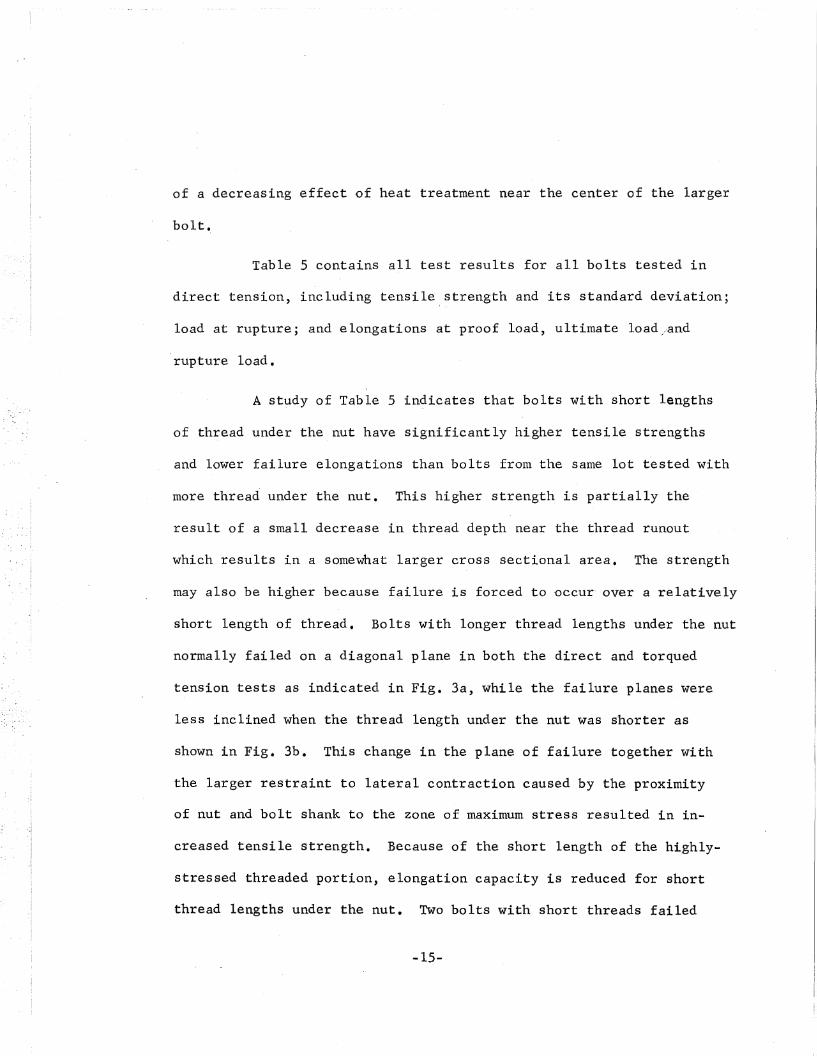
Table 5 contains all test results for all bolts tested in
direct tension, including tensile, strength and its standard deviation;
load at rupture; and elongations at proof load, ultimate load/and
rupture load.
A study of Table 5 indicates that bolts with short lengths
of thread under the nut have significantly higher tensile strengths
and lower failure elongations than bolts from the same lot tested with
more thread under the nut. This higher strength is partially the
result of a small decrease in thread depth near the thread runout
which results in a somewhat larger cross sectional area. The strength
may also be higher because failure is forced to Dccur' over a relatively
short length of thread. Bolts with longer thread lengths under the nut
normally failed on a diagonal plane in both the direct and torqued
tension tests as indicated in Fig. 3a, while the failure planes were
less inclined when the thread length under the nut was shorter as
shown in Fig. 3b. This change in the plane of failure together with
the larger restraint to lateral contraction caused by the proximity
of nut and bolt shank to the zone of maximum stress resulted in in
creased tensile strength. Because of the short length of the highly
stressed threaded portion, elongatipn capacity is reduced for short
thread lengths under the nut. Two bolts with' short threads failed
-15-

by thread stripping but only after' having reached an ultimate load
well above the specified minimum tensile strength.
A comparison of the behavior in direct tension of the A325,
A354BC and A490 (or A354BD) bolts is made in Fig. 4. The curves shown
are for bolts having nearly equal grip lengths and thread lengths
under the nut. It is obvious that increased bolt strength is accom-
panied by a decreased deformation capacity.
Although a threaded fastener is not a simple tension bar,
its elastic behavior may be computed by using a few simplifying
assumptions. First the threaded portion is considered as a uniform
shaft having a cross-sectional area equal to the stress area listed
in the applicable ASTM specification. Secondly it is assumed that
the full tensile load in the bolt is carried between the inner face
of the bolt head and a point centered between the two faces of the
nut. It is further assumed that no stress causing axial deformation
exists beyond these limits. The total elongation of the bolt as
measured by the C-frame extensometer at any given elastic load can
then be computed from the formula:
-16-
where
8 = fEbE . A
8 = total axial deformation in in.,
p = axial load in kips,
E = modulus of elasticity in kips per sq. in.,
L = length in in., and

A = cross sectional area in sq. in.
Table 6 lists the computed elongations at proof load for
both direct and torqued tension tests. The computed values were with
in 8% of the measured values for the direct tension tests.
3.3 TORQUED TENSION TESTS
Two series of torqued tension tests were conducted, one with
a heavy commercial lubricant applied to the threads of bolt and nut
and the other with only a light shipping oil, or simulated shipping
oil in the case of the four lots of A354 Be bolts. In all other
respects the procedures of the two series were identical. Figure 5
shows the load-elongation relationsh~p in torqued tension with threads
as received for the ED lot A354 BD bolt. The load at 1/2-turn is just
above proof load.
Table 7 shows the results of torqued tension tests of bolts
coated with shipping oil, while Table 8 lists the results of tests of
bolts coated with the heavy lubricant. These tables show the mean
values of load at 1/2 turn-of-nut from snug, torqued tensile strength,
rupture load; and the elongations at proof load, at 1/2 turn-of~nut,
at ultimate load, and after rupture. The nut rotation from snug to
failure is also listed as are the standard deviation of the mean values
of tensile strength and the torqued ultimate load expressed as a per
centage of the ultimate load in direct tension for the same lot. In
addition to these values, Table 7 reports load and elongation at 5/8
-17-

turn-of-nut from snug. These values are reported because they are the
closest available to the 2/3 turn specified in the 1964 specification
of- the Research Council. for bolts having lengths under head greater
than eight inches or eight diameters whichever is smaller.
The mean curves of Figs. 2 and 5 and the mean curve in
torqued tension with lubricated threads are shown in Fig. 6 for
comparison ,of the results of the different types of tests. The ulti-
mate strength in direct tension is substantially greater than that in
torqued tension. Many investigators have observed this increase in
A325, A354, and A490 bolts(l)(2)(3). Thread lubrication had little
effect on the torqued tension behavior.
The lower tensile strength of bolts in torqued tension has
b 1 · d h · 11 · h h·· 1 ' h (12) (13)een exp a~ne t eoret~ca y w~t t e pr~nc~pa stress t eory .
and the principal strain theory(l2). Lubrication could allow a higher
ultimate tensile strength because the shear stress component induced
by torque may be reached. Lubrication is thought to have a small
effect because the high bearing stresses encountered cause the struc
tures of the lubricant to break down(l3).
The reductio~ in tensile strength occurred in all- of the
torqued tension tests listed in Tables -7 and 8. The percentage that
torqued tension ultimate strength is of direct tensile strength,
recorded in bot~ tables, averages about 85% for threads coated with
shipping oil anQ about 88% for heavily lubricated threads. For the
A354 Be bolt, proof Load is 84% of specified -ten~ile strength and for
the A354 BD and A490 bolts it is 80% of specified tensile strength.
-18-

Had the bolts tested in this program been minimum strength bolts, some
of the 'lots mig~t have had ultimate ~trengths in torqued tension below
proof load. Regardless of the nut rotation specified, proof load
could not be induced in such bolts.
Figure 7 allows comparison of the typical behavior of A325,
A354 Be and A354 BD (or A490) bolts in torqued tension. Each lot
shown was tested with 3/4 in. thread under the nut and a grip length
of either 4-1/4 or 4-1/2 in. As in the direct tension tests, the
higher-strength bolts show smaller elongations to failure under torqued
tension. The higher-strength bolts also reach ultimate load at a
smaller elongation and the load then drops off more quickly than with
A325 bolts. This was also true for the direct tension relationships
shown in Fig. 4.
Another interesting point is that the mean elongation at
1/2 turn, given in Tables 7 and 8, is fairly constant for most of the
bolts tested. For the higher-strength, long-grip bolt this elonga
tion may be entirely due to elastic deformations, whereas for the
lower-strength bolt both elastic and inelastic deformations may be
included. For example, Fig. 8 compares the torqued tension behavior
of A325 bolts with a grip 'length of 8-1/4 in. with that of A490 bolts
with a grip length of 9-11/16 in. The elongation and load at 1/2 turn
of nut are nearly identical for the two bolt lots. The 1/2 turn is
well into the inelastic range and above proof load, for the· A325 bolt;
howeve~, it is in the elastic range and below proof load for the A490
-19-

bolt. In general, as bolt strength and grip length increase so does
the elongation to the elastic limit or proof load. The compressive
deformation of the material being gripped also increases with higher
bolt tension. These effects combine to require larger nut rotations
to induce proof load in the high-strength bolts, especially those with
long grip lengths.
A study of Fig. 9 yields further interesting information.
This figure derived from Table 7, is a bar graph of the loads at 1/2
and 5/8 turn and the ultimate load for the A354 BD and A490 bolts for
torqued tension tests with threads as received. The load scale is
non-dimensianalized by dividing all loads by the proof load so that
7/8 and 1 in. bolts may be compared. The ultimate load is shown to
indicate the remaining load available at 1/2 and 5/8 turn-of-nut.
The load at 1/2 turn-af-nut is consistently below proof load for the
bolts with longer grip lengths for the reasons just presented. Even
at 5/8 turn-of-nut, two of the lots with longer grips had mean loads
below proof load. Thread length under the nut showed no consistent
effect on the loads at 1/2 and 5/8 turn. Table 8 shows that thread
lubrication did nothing to improve this behavior. Although the load
at 1/2 turn-of-nut was above proof load for most of the bolts with
short grip lengths, it usually remained within the elastic range and
was therefore very sensitive to minor changes in elongation.
The effects of grip length on the load-elongation relation
ship of the alloy steel bolt are illustrated in Fig. 10 for two lots of
-20-

7/8 in. A490 bolts. Both lots had the same thread length under nut.
The relationship for the shorter bolt, shown by the solid line, has
a steeper elastic slope than that for the longer bolt; and although
the elongations at 1/2' turn-of-nut are approximately equal for the
two lots, the resulting load is above proof load for the shorter
grip bolt and below proof load for the longer.
The elastic deformation of bolts in torqued tension is
nearly the same as in direct tension and can be computed in the same
way. Table 6 shows the comparison between the computed values of
elongation at proof load and the measured values in torqued tension
taken from Tables 7 aJ.1.d -8. For bolts in which ine lastic deformations
are not present, the induced preload due to a specified elongation
can be predicted reasonably well.
Figure 11 emphasizes the differences resulting from tests
of bolts from the same lot with different lengths of thread under the
nut. As with the direct tension tests, a shorter length of thread
under the nut results in a higher ultimate load. The reasons for
this are the same as for the direct tension tests, This behavior
was not appreciably affected by thread lubrication.
The nut rotation to failure ranged from 1 to 1-7/8 turns
for torqued tensinn tests with threads as received and from 1-1/8 to
1-7/8 turns with lubricated threads. Lubrication had no significant
effect on the rotation to failure. The nut rotation to failure is
-21-

plotted versus the thread length under nut for the 7/8 in. bolts in
Fig. 12 Mean curves are shown in the figure, one for A354 Be bolts,
one for A354 BD and A490 bolts, and one taken from Ref. 1 for A325
bolts. In all three cases there is an increase in the nut rotation
to failure with an increase in the thread length under the nut.
While this is very pronounced for A325 bolts, it is less for alloy
steel bolts. The "I-in. alloy steel holts show trends much like the
7/8 in. bolts. Increased nut rotation to failure depends directly
on the incre'ased elongation capacity of ,bolts with greater thread
length under nut. The more· the bolt stretches, the greater is the
nut rotation that must be applied to cause bolt failures.
The reduced ultimate load for these boits in torqued ten
sion and the high ratio of proof load to specified ultimate load
(0.80) for the A354 BD and A490 holts make it advisable to consider
a minimum preload for installation somewhat below proof load. It
is possible that the ultimate load in torqued tension could he less
than.80%, of that in direct tension, below proof load for minimum
strength bolts •
. 3.4 COMBINED TORQUED-DIRECT TENSION TESTS
Figure 13 displays the results of this study. The bolts
were first tightene4 to 5/8 turn_from snug and then loaded in direct
tension. The transfer from torqued to direct tension is indicated by
the sharp turn upward of the load-elonga~ion relationship. The curve
-22-
then quickly approaches the direct tension curve for the same lot of
bolts, shown as a dashed line. The curve then quickly approaches the
direct tension curve for the same lot of bolts, shown as a dashed line.
The curve showing the load-elongation relationship in torqued tension
with threads as received is also included as a frame of reference.
Bolt fractures were all simila-r to those in direct tension with no
visible influence of torsional shearing stresses.
One lot of A354 Be bolts and three lots of A490 bolts were
first tightened to 5/8 turn and then loaded in direct tension. The
mean ultimate loads reached during these tests ranged from 97 to 103%
of the corresponding values in direct tension.
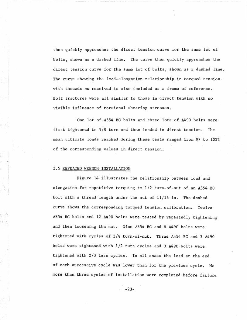
3.5 REPEATED WRENCH INSTALLATION
Figure 14 illustrates the relationship between load and
elongation for repetitive torquing to 1/2 turn-af-nut of an A354 Be
bolt with a thread length under the nut of 11/16 in. The dashed
curve shows the corresponding torqued tension calibration. Twelve
A354 BC bolts and 12 A490 bolts were tested by repeatedly tightening
and then loosening the nut. Nine A354 BC and 6 ,A490 bolts were
tightened with cycles of 3/4 turn-of-nut. Three A354 Be and 3 A490
bolts were tightened with 1/2 turn cycles and 3 A490·bolts were
tightened with 2/3 turn cycles. In all cases the load at the end
of each successive cycle was lower than for the previous cycle. No
more than three cycles of installation were completed before failure
-23-

for the bolts tightened to 3/4 turn-of-nut, while the lot tightened to
1/2 tu~n withstood an average of four cycles before failure.. For
every bolt tested the installation time for the second cycle was
nearly triple that of the first. Becaus,e of the incremental nature
of testing, this' increase in time was not measured precisely or
recorded.
These bolts were more sensitive to repeated applications of
load than A325 bolts(l). This severity is the result of greater cumu
lative thread damage caused by high loads and high stress concentrations
acting on threads of the same geometry as the threads on the A325 bolts.
The behavior of the A490 bolts seemed to be no more critical than that
of the A354 BC bolts. However, a direct comparison is difficult
because of the limited number of tests conducted.
3.6 BOLTS INSTALLED IN STEEL PLATE
Table 9 summariz,es the" results of tests of holts installed
in steel plates rather than in the hydraulic bolt calibrator. Three
A354 BC bolts, 9 A354 BD bolts, and 21 A490 bolts were tested. The
table lists mean experimental values of elongation at 1/2 turn-of-nut,
elongation after rupture, and nut rotation to failure. Also listed
is the computed load at 1/2 turn as determined from the measured
bolt elongation applied to the mean torqued tension load-elongation
curve for tests of the same lot of bolts in the bolt calibrator.
This load is then tabulated as a percentage of the ,load at 1/2 turn
-24-
for bolts tested under torqued tension in the bolt calibrator.
The most striking resu.it indicated in the table is that
the elongation at 1/2 turn-of-nut for bolts tightened in solid plate
averages about 0.03 in. while in the bolt calibrator the average
elongation was closer to 0.02 in. for the same lots (see Table 7).
This results in an increase in the load at 1/2 turn above that found
in the bolt calibrator. Apparently the elongation and corresponding
tension of a bolt tightened to a given nut rotation in a well com
pacted joint may be substantially above the values obtained using a
hydraulic bolt calibrator. In the last two columns of this table are
shown the nut rotations to failure for these tests and those listed in
Table 7 for the regular torqued tension tests. It will be seen that
in the steel plate, rotation to failure averages about 1/8 turn less
than for the tests conducted in the bolt calibrator. It is apparent
that the increased deformation of the bolt calibrator results in an
increase in the nut rotation required to cause failure.
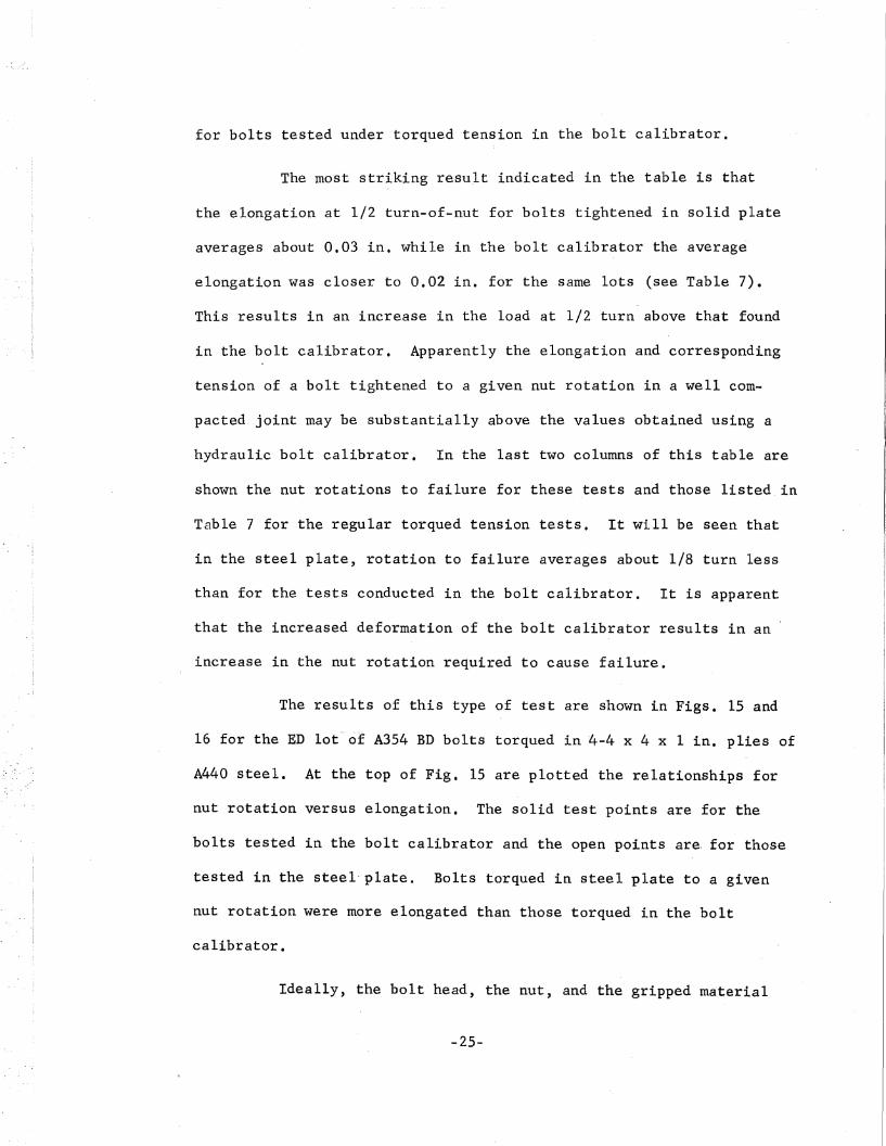
The results of this type of test are shown in Figs. 15 and
16 for the ED lot-cit A354 BD bolts torqued in 4-4 x 4 x 1 in. plies of
A440 steel. At the top of Fig. 15 are plotted the relationships for
nut rotation versus elongation. The solid test points are for the
bolts tested in the bolt calibrator and the open points are. for those
tested in the steel" plate. Bolts torqued in steel plate to a given
nut rotation were more elong·ated than those torqued in the bolt
calibrator.
Ideally, the bolt head, the nut, and the gripped material
-25-

would be completely rigid and the entire deformation would be in the
form of elongation of the bolt shank and threads. For one revolution
of the nut, this deformation would be equal to the distance between
threads. This ideal behavior is shown as a dashed curve in Fig. 15.
The three curves shown at the top of the figure all originate at the
mean snug elongation of 0.0025 in. as measured during the torqued ten
sion calibration. Bolts in the steel plate were purposely snugged to
this elongation.
The bottom half of Fig. 15 is the mean relationship between
bolt tension and elongation for this lot of bolts in torqued tension.
By projecting the elongations from the elongation-rotation curves onto
the mean load-elongation curve in this manner, load-versus-nut-rot,Btion
relationships cari be plotted for the so~id plate tests and for the ideal
case of completely rigid bolt head, nut, and gripped material. These
relationships are plotted in.Fig. 16. The shape of the curve for the
ideal case is the same as the load-elongation curve since in this case
there is a direct relationship between nut rotation and bolt elongation.
The computed curve for the solid plates deviates from this curve at a
constant rate, indicating the flexibility of the system. Proof load
was reached in this case at just over 1/4 turn-of-nut. The load-rota
tion curve obtained in the bolt calibrator is also compared with the
ideal and solid plate curves in Fig. 16. This curve indicates the
greatest flexibility with large deformation at small rotation indi
cating a slight amount of play in the hydraulic system itself, prob
ably, due to entrapped air. Proof load was not reached in this case
until just under 1/2 turn-af-nut. These three curves also indicate
-26-

smaller nut rotations to failure for the stiffer assemblies.
3.7 CONTINUOUSLY TORQUED BOLTS
Two lots of A354 Be and three lots of A490 bolts were
torqued continuously to either 1/2 or 3/4 turn-of-nut to determine
whether the bolts were affected by incremental tightening. The
resulting variation was no more than ten percent in either direc
tion for load or elongation ·at the specified number'of turns.
Similar results were reported in Ref. l.for A325 bolts.
-27-

The following con-elusions and reconnnendations are based upon
the tests described in this report.
1. Coupon tests do not accurately reflect the true strength
of a bolt when they are cut concentrically with the bolt axis, primar
ily because of the reduced effect of heat treatment near the center of
the bolt. The inaccuracy was more pronounced for the I in. bolts than
for the 7/8 in. bolts as is evident in Table 3.
2. The elastic behavior of high strength bolts in direct
and torqued tension can be predicted using the simple theory for de
formation of axially loaded members (Table 6).
3. All bolts had lower ultimate loads when tested in torqued
tension than in direct tension. Ultimate loads of bolts torqued with
shipping oil as the only lubricant varied from 78 to 92% of those
tested in direct tens,ion, with an ave"rage value of about 85%. Heavy
lubrication resulted in slightly increased torqued ultimate loads for
the A354 BD and A490 bolts with short lengths of thread under the nut
(Fig. 6).
4. A decrease in the length of thread under the nut results
in increased ultimate strength and reduced elongation capacity for
both d~rect and torqued tension tests of alloy steel bolts.
5. When bolts were tested in the hydrauli~ bolt calibrator,
-28-

the preload induced by 1/2 turn-af-nut exceeded proof load for all lots
of A354 Be bolts and for most of the A354 BD and A490 bolts with short
grip lengths. ' However, these loads usually remained in the elastic
range and were therefore subject to large variations for relatively
small variations in elongation. For the A354 BD and A490 holts with
grip lengths above seven inches, proof load could not be induced by
1/2 turn-of-nut. Even at 5/8 turn-of-nut, the preload induced in the
bolt calibrator was often less than proof load.
6. Tests of A354 and A490 bolts tightened in steel plate
indicate that fewer turns of nut are required to induce a given pre
load than in the holt calibrator. Less nut rotation to failure was
also observed in steel plate. These effects are due to the inherent
flexibility of the bolt calibrator.
7. The 1 in. A354 Be bolts behaved in a somewhat less
ductile manner than 7/8 in. A354 Be bolts. The nut rotation to failure
averaged about 1/4 turn less for the 1 in. holts than for the 7/8 in.
bolts. This was not the case for the A354 BD and A490 bolts.
8. Except for providing a 'higher ultimate strength in
torqued tension for the A354 BD and A490 bolts with short thread
lengths under nut, heavy thread lubrication had little apparent effect.
For the A354 Be bolts, the freshly applied shipping oil seemed to be
slightly more beneficial in producing high ultimate loads and large
nut rotations to failure than the heavy lubricant.
9. Nut rotations from snug were found to-vary from one to
-29-

nearly two full turns before bolt failure, increasing with ~ncreased
thread length under the nut. In general, the, A354 Be bolt withstood
more turns to failure than the A354 BD" or A490 bolt.
10. Direct tension tests after preloading the bolt indicate
that pre loading with a wrench does not reduce the tensile strength.
11. Repeated tightening of alloy steel bolts into the
inelastic range resulted in a marked reduction in induced tension
with each installation and a marked increase in installation time.
12. The behavior of alloy steel bolts torqued continu
ously 'to a given nut rotation does not differ from that of incre
mentally-tightened bolts.
13. Consideration should be given to specifying an in
stalled preload less than the proof load for alloy steel bolts.
-30-

ACKNOWLEDGE:MENTS
The authors wish to express their sincere gratitude to Dr.
Lynn S. Beedle, Director of Fritz Engineering Labotatory, for his
supervision, encouragement, and critical review of this work, and to
James Wallaert and Gordon Sterling for their valuable .advice and help
during the testing. Thanks are also extended to Miss V~lerie Austin,
who typed the manuscript; to Richard Sopko for his excellent photo
graphy; and to H. A. Izquierdo and R. J. Wiess, who so patiently pre
pared the drawings.
The Russell, Birdsall and Ward Bolt and Nut Co. contributed
most of the bolts tested. Bethlehem Steel Co. donated four lots of
A490 bolts and also supplied the air compressor and impact wrench.
The Skidmore-Wilhelm Co. furnished the large Model K hydraulic bolt
calibrator for tests of the one in. bolts. Sincere thanks go to each
of these firms and to the people at each firm through whom these contri
butions were arranged.
This study has been carried out as a part of the research pro
ject on "Large Bolted Connections" being conducted at Fritz Engineering
Laboratory; Departmen.t of Civil Engineering, Lehigh University. Professor
William J. Eney is the head of the department. The project is sponsore~
financially by the Pennsylvania Department of Highways, the U. S. Depart
ment of Commerce - Bureau of Public Roads, and the American Institute
of Steel Construction. Technical guidance is provided by the Research
-31-

Council on Riveted and Bolted Structural Joints through an advisory
committee under the chairmanship of Dr. John L. Rumpf.
-32-

TABLE 1
DESCRIPTION OF SPECIMENS
I L I
~ Grode 2HHeavy Hexaoon Nut
Bolt ASTM Head* Nominal Type of L g tLot Designation Type Diameter, Thread inches inches inches
inches-
JAC-7-ZS A354BC H 7/8 Cut 5.25 3.62 0.125,j
tor
AC-7-9S " H 7/8 II " 4.06 0.562
J rBC-S-ZS " H 1 II 11 3.37 0.125
II H 1 II II 3.94 0.688Be-8-liS
'\;' CC-7-12S " R 7[8 Rolled 5.50 4.25 0.75
DC-8-16S II R 1 " " " 1.00
~- AD-7 -28 A490 H 7/8 Cut 5.25 3.62 0.125.~.) '~
1~ AD-7-9S II H 7/8 11 If 4.06 0.562
J LBD-S-ZSII H 1 II ff 3.37 0.125
BD-8-11S " H 1 " II 3.94 0.688
,) rCD-7-2L II H 7/8 " 9.25 7 0 62 0.125
lCD-7-9L II H 7/8 " " 8.06 0.562
j r DD-8-ZL II H 1 II " 7.37 0.125, ,1»{-- DD-8-11L II H I II II 7.94 0.688
"'! ED-7-12S ' A354BD R 7/8 Rolled 5.50 4.25 0.75
~J FD-8-16S If R 1 II " II 1.00
"g GD~7-12L " R 7/8 Cut 9.50 8.00 0.75
HD-8-16L II R 1 " " 7.75 1.00
,t rLI-7-2S A490 H 7/8 Rolled 5.50 4.12 0.125
LLI-7-9S If H 7/8 II 11 4.56 0.562
'L~ r AB-7 -2L II H 7/8 Cut 9.50 8.25 0.125-. {
!
~ AB-7-9L II H 7/8 If II 8.69 0.562
·1 KK-7-2S " H 1/8 Rolled 5.50 4.19 0.125
,.J JJ-8-6S II H 1 II " 4.12 0.375
*From Amarican St andards As s oc • BI8.2: H identifies Heavy Semi-finished Hexagon HeadR identifies Regular Semi-finished Hexagon Head
-33-..

TABLE 2
SPECIFIED PHYSICAL PROPERTIES
Bolt Stress ASTM Coupon Properties Bolt PropertiesDiameter, Area, Designation Tensile % Elong. % Red. Proof Tensile* Hardness, Hardness,inches sq. in. Strength, in 2 inches of area Load, Strength Rockwell C Brinel1
min, ksi min. min. min, kips min, -kips
7/8 0.462 A325 - - ... 36.05 53.15 22-34 235-321
" " A354B.C 125 16 50 48.50 57.75 25-34 . 255-321
II II A354BD 150 14 35 55.45 69.30 32-38 302":'352Iw II It A490 150 14 35 55.45 69.30 32-38 302-352+'I
1 0.606 A325 - - - 47.25 69.70 22-34 235-321
" II A354BC 125 16 50 63.65 75.75 25-34 255-321
" " A354BD 150 14 35 72.70 90.90 32'!:'38 302-352
" If A490 150 14 35 72.70 90.90 -32-38 302~352
*Specified for bolts tested with 6 full threads under the nut, acco~ding to ASTM Des·ignation A370, Supplement III
Tab Ie 3
COUPON TEST RESULTS
BoltLot
ASTMDesignation
Number Tensile % ASTMTested Strength Minimum
ksi
E1ong. % ASTM Red. of % ASTMin 1.9"% Minimum Area, % Minimum
AC A354BC 3 140.3 112 21.2 132 57.2 "114
BC II 3 126.2 101 22.1 138
CC II 3 133.0 106 21.6 135 62.2 124
DC II 3 131.6 105 22.6 141 63.1 126
AD A490 3 162.5 108 18.0 128
BD II 3 147.7 98 14.6 104 59.1 169
CD II 3 156.1 104 18.8 134 59.8 171
DD II 3 156.6 104 19.8 142 59.8 171
ED A354BD 3 164.9 110 16.6 118 59.1 169
FD II 3 149.8 100 16.7 119 58.1 166
GD " 3 160.9 107 18.8' 134 58.1 166
lID II 3 165.1 110 16.3 116 55.5 159
LI A490
AB " 3 151.6 101 21.4 153 52.9 151
KK II 3 153.4 102 20.0 143 55.5 159
JJ 11
Table 4
COMPARISON OF BOLTS TO ASTM SPECIFICATIONS
Bolt ASTM Hardness, Hardness, Tensile Stren th*Lot Designation Rockwell C Brinel! Number Mea~, % ASTM
Tested kips Minimum
AC-7-9S A354BC' 30 269 3 65.0 113
Be-8-lIS II 30 281 3 82.9 109
~C-7-12S~I 31 277 3 62.3 108
DC-8-16S II 32 288 3 83.1 110
AD-7-9S A490 34 329 3 76.5 110
BD-8-11S II 35 328 3 100.0 110
CD-7-9L II 35 328 3 74.5 108
DD-8-11L II 34 304 3 96.7 106
ED-7-12S A354BD 38 338 3 77.8 112
FD-8-16S " 37 331 3 99.3 109
GD-7-12L II 32 331 3 75.5 109
lID-8-16L II 36 332 3 100.5 110
LI-7-9S A490 34 318 5 72.1 104
AB-7-9L " 34 307· 5 70.8 102
KK II 35 323 72.3+ 104
JJ II 35 323
*A11 results shown here are for approximately six threads under the nut as specifiedin ASTM,A370
+From mill report -35-

TABLE 5 .
DIRECT TENSION TEST RESULTS
Bolt ASTM Number of Ultimate Load Rupture Elongation, inchesLot Designatfon Specimens Mean Std. Dev. % ASTM Load At Proof At Ult. After
Tested kips kips Minimum kips Load Load Rupture
AC-7-2S A354BC 3 72.6 1.88 126 64.3 .0114 .0854 0.173AC-7-9S 11 3 65.0 1.57 113 52.0 .0136 .0758 0.190BC-8-2S II 3 91.0 2.26 120 76.3 .0115 .0783 0.140Be-8-llS 11 3 82.9 1.60 109 61.7 .0139 .0919 0.263CC-7-12S " 3 62.3 0.20 108 48.7 .0139 .0900 0.300DC-8-16S " 3 83.1 1.22 110 64.0 .0141 .1079 0.293
fAD:7-28-'- A490 3 83.1~ 2.63 120 78.3 .0134 •.0459 0.083L-AD-7-9S " 3 76.5- 1.51 110 68.7 .0156 .0605 0.1131"'BD-B-2S " 3 102.11 1.83 112· 92.0 , .0138 .0611 0.127LBD-8-11S " 3 100.0: 0.20 110 92.3 .0161 .0747 0.143
I rCD~7-2L c
11 3 82.6j 1.25 119 79.2 .0256 .0702 0.120UJ0'\ lCD-7-9L' " 3 74.5- . 0.44 lOS. 69.8 .0281 .0807 0.120I
rDD-B-2L II 3 105.41 0.71 116'- 93.3 .0258 .0841 0.147JlD-8..1lL II 3 96.7 ' 0.53 106~ 85.3 .0277 .0909 0.173ED-7-12S A354BD 3' 77.,·8·....· 0.67 112 71.7 .0159 .0619 0.120FD-8-16S· 11 3 99411-3 - 2.18 109 8;1..3 .0169 .0899 0.207GD":7-12L II 3 75.5 _. 0.82 109 71.0 .0275 .0839 0.137HD-8-l6L II 3 100.5 :" 1.25 110 91.7 .0280 .0938 0.137
[LI-7-2S A4~O 5 76.0:, - 0.54 110 67.0 .0150 .0510 0.137LI-7-9S " 5 72.~ 0.17 104 59~.0 .0170 .0650 0.245
[AB-7-2L " 5 73.- -r 1.59 106 65.0 .0280 .0779 0.120AB-7-9L II 5 70.,SJ 1.69 102 61.0 .0290 .0846 0.180
-KK-7-2S .11 5 77.9 0.44 112 69.3 .0156 .0607 0.115-JJ-8-6S II 5 99.2 ./ 1.57 109 85.0 .0160 .0625 0.189

THEORETICAL ELASTIC BEHAVIOR
Bolt Pr.oof Calc. E1ong. Elong. at Proof Load/Calc. Elong.Lot Load at Proof Load
kips inches Direct Torq. Ten. Torq. Ten.Tension threads as threads
re·ceived lubr.
AC-7-2S 48.5 .0115 0.99 1.06 1.05AC-7-9S " .0130 1.05 1.27 ~.31
BC-8-2S 63.65 .0112 1.03- 0.98 1.12BC-8-11S " .0131 1.06 ~.15 1.22CC-7-12S 48.5 .0138 1.01 1.23 1.30DC-8-168 63.65 .0142 0.99 1.06 - 1.09AD-7-2S 55.45 .0132 1.02 1.11 1.02·AD-7-9S " .0150 1.04 1.10 1.30BD-8-2S 72.70 .0127 1.09 1.10 1.10BD-B-llS 11 !f0l50 1.08 1.10 1.20CD-7-2L 55.45 .0257 1.00 1.05 1.05CD-7-9L " .0275 1.02 1.04 1.05DD-8-2L 72.70 .0252 1.02 1.03 1.01DD-8-11L " .0275 1.01 1.02 1.02ED-7-12S 55.45 .0157 1.01 1.07 0.99FD-8-16S 72.70 .0162 1.04 1.08 1.36GD-7-12L 55.45 .0275 1.00 0.96 0.98HD-8-16L 72.70 .0273 1.03 0.99 1.03L1-7-28 55.45 .0148 1.01 1.08L1-7-98 " .0165 1.03 1.09AB-7-2L " .0276 '1.01 1.01AB-7-9L " .0295 0.98 1.05KK-7-2S " .0150 1.04 1.16JJ-8-68 72.70 .0153 1~O5 1.03
-37-

TABLE 7
TORQUED TENSION TESTRE8ULT8
Threads as Received
L~\J /(-~J
t)
\ ~~ ,t:,
Bolt Proof Number of Load at Load at Ultimate Load Rupture Elongation, inches Nut Rotatior-Lot Load Specimens 1/2 turn 5/8 turn Load, to Rupture
kips Tested kips kips Mean, Std. Dev. % Direct kips At Proof At 1/2 At 5/8 At U1t. After revs.kips kips Tension Load Turn Turn Load Rupture
Ultimate
,~~ /48.50 57.6 61.3 1.36 0.113 1-1/2\~-2S/ 3 49.1 84.5 47.0 .0122 .0128 .0210 .0512
C-7-9'S II 3 52.8 55.1 56.5 0.87 87 36.7 .0165 .0260 .0369 .0614 0.167 1-3/4f [B' -.(28 63.65 3 75.3 77.8 78.5 3.50 86.5 43.3 .0110 .0202 .0308 .0389 0.110 1-1/4:1 ' ~!Y':8~,lS " 3 70.2 72.2 72.7 4.49 88 55.3 .0150 .0291 .0304 .0473 0.110 1-1/4i,/-cC-7-1~ 48.50 3 51.1 53.6 55.7 0.30 89.5 40.3 .0170 .0227 .0345 .0669 0.160 1-7/8
DC-8-16S 63.65 3 70.8 73.5 74.5 1.50 90 49.7 .0150 .0299 .0430 .0562 0.170 1-3/4
1(AD-7-2S --- 55-.-45,._-_ _3 48.9 - ---62-.~ 70.5 1.82 85 58.0 .0147 .0127 .0185 .0376 0.080 1-1/4
I I'rl1f:i .•. ' AD-7-9SII 3 60.9 64.8 66.9 2.11 87.5 53.0 .0165 .0209 .0313 .0510 0.120 1-3/8
VJ"~ (BD-8-28 72.70 3 84.5 90.7 90.7 0.58 89 71.7 .0140 .0181 .0280 .0280 0.103 1ex> ... BD-8-11S " 3 72.5 80.5 83.0 7.86 83 58.0 .0165 .0173 .0273 .0441 0.120 1-3/8I ~0
55.45 3 45.7 50.1 71.9 1.-86 87 66.7 .0270 .0219 .0244 .0652 0.110 1-3/8CD-7-2LLCD-7-9L ' II 4 46.9 55!"7. 62.. 6 2.06 &4 56.2 .0285 .0240 .0316 .0610 0.105 1-1/4DD~8-2L 72.70 3 64.0 80.0~ 90-.3 1.15 85.5 70.7 .0260 .0223 .0289 .0498 0.107 1-1/4'DD-8-11L " 3 67.0 78.8U' 84.0 2.65 87 59.7 .0280 .0262 .0345 .0537 0.147 1-5/8
fF--'b~::Y~~ 55.45 4 59.2 64.0 67.6 1.95 87 52.8 .0168 .0183 .0279 .0484 0.145 1-3/8~ FD-8-16S 72.70 3 77.8 83.8 88.2 2.36 89 68.8 .0175 .0222 .0298 .0541 0.143 1-3/8~ GD-7-12L 55.45 3 32.7 42.6 69.3 0.87 92 58.0 .0265 .0155 .0206 .0725. 0.127 1-3/4L HD-8-16L 72 •.70 3 66.7 8,l.5 91.2 1.44 91 75.3 .0270 .0250 .0336 .0616 0.173 1-3/4
T1LI-7-2S* 55.45 5 53.4 59.9 61.1 2.80 80.5 40 .0160 .0162 .0216 .0260 0.075 1-1/4LI-7-9S* If 5 50.0 55.4 58.4 3.00 81 34 .0180 .0156 .0206 .0310 0.110 1-5/8
1~Al3 ...7-2L* II 6 48.6 5].5 65.4 2.80 89 52 .0280 .0235 .0291 .0530 0.080 1-3/8t U-7-9L*
If 5 41.1 50.8'----- 61.8 2.18 87 50 .0310 .0219 /.0268 .0700 0.114 1-3/41 KK-7-2S " 10 56.2 60.2 60.4 3.50 77.7 47.5 .0173 .0182 .0276 .0295 0.062 i4 JJ-8-65* 72.70 5 81.0 85 •.8 87.3 1.26 87.9 64 .0158 .0201 .0311 .0466 0.145 1-1/2
*Snug load was taken as 10 kips for these lots
/lJJI(>
(]VI; "~I! t.
lQ-./·

Table 8
TORQUED TENSION TEST RESULTS
Threads Lubricated
Bolt Proof Number of Load at Ultimate Load Rupture Elongation, inches Nut RotationLot Load, Specimens 1/2 turn Load to Rupture
kips Tested kips Mean, Std. Dev. %Direct kips At Proof At 1/2 At Ult. After revs.kips kips Tension U1t. Load Turn Load Rupture
AC-7-2S 48.50 3 51.5 62.5 1.13 86 44.3 .,0121 .0130 .0555 0~117 1-5/8AC-7-9S 11 3 52.0 56.8 0.50 87.5 40.3 .0170 .0225 .0583 0.157 1-3/4I
VJ BC-8-2S 63.65 3 74.2 76~5 1.80 84 52.0 .0125 .0208 .0371 0.103 1-1/4\0 BC-8-11S " 3 67.2 71.5 3.00 86.5 51.3 .0160 .0220 .0518 0.133 1-1/2I
CC'-7-12S 48.50 3 50.8 55.2 0.53 89 43.0 .0180 .0231 .0628 0.160 1-7/8DC-B-16S 63.65 3 70.2 73.7 3.34 89 54.7 .0155 .0243 .0608 0.153 1-3/4AD-7-2S 55.45 3 60.3 78.6 1.46 94.5 59.3 .0135 .0152 .0496 0.127 1-'1/2AD-7-9S " 3 58.0 65.8 6.25 86 50.3 .0195 .0199 .0537 0.150 1-5/8BD-8-2S 72.70 3 83.5 91.3 7.37 89.5 73.7 .0140 .0178 .0367 0.100 1-1/8BD-B-llS " 3 68.0 78.8 5.80 79 60.3 .0180 .0170 .0401 0.117 1-3/8CD-7-2L 55.45 3 47.8 76.1 0.93 92 58.0 .0270 .0228 .0627 0.143 1-3/4CD-7-9L " 3 46.7 66.6 0.82 89.5 56.3 .0290 .0239 .0630 0.133 1-1/2D~-8-2L 72.70 3 58.3 99.0 2.78 94 77.0 .0255 .0201 .0603 0.115 1-5/-8DD-a-IlL " 3 69.7 85.0 3.28 88 58.7 .0280 .0269 .0684 0.153 1-3/4ED'-7-l2S 55.45 3 61.9 68.5 0.45 88 58.0 .0155 .0192 .0489 0 •.137 i.-1/2FD-8-16S 72.70 3 61.3 85.5 8.26 86 66,3 .0220 .0164 .0611 0.180 1-7/8GD-7-12L 55.,45 3 36.1 68.1 0.70'- '90.5 60.3 .0270 .0163 .O~51 0.107 1-5/8HD-8-1.6L 72.70 3- 61.7 90.3 2.08 90 68.0 .0280 .0236 .0869 0.170 1-7/8

TABLE 9
BOLTS INSTALLED IN STEEL PLATE
Bolt Number of Elong. at Computed % of Load Elong. Nut Rotation Nut RotationLot Specimens 1/2 turn Load 'at at 1/2 turn after to Rupture, to Rupture
Tested of Nut, 1/2 turn from Table 7 Rupture, revs. from Table 8inches of Nut, inches
kips
Be-8-llS 3 .0392 71.6 102 0.093 1 1-1/4
I BD-8-2S 3 .0286 89.5 106 0.070 .1 1
k BD-8-11S 3 .0386 82.0 113 0.097 1 1-3/8
~i ED-7-12S 3 .0346 ' 65.5 I. 110 0.117 1-1/8 1-3/8
{'"~\( \ FD-B-16S 3 .0282 83.0 107 .0.183 1-3/4 1-3/8
GD':7-12L 3 .0359 63~O (i92b
). 0.137 1-1/2 1-3/4,~:",..,:=r"":-.\'"';'
rI-7-12S 5 .0286 60.5 113 0.096 1-1/4 1-1/4
~~~; LI-7-9S 5 .0229 57.3 . 114 0.100 1-1/2 1-5/8
'KK-7-2S. 5 .0248 59.5 106 0.060 7/8 1
-40-

200 _-----r--- -----r-~--_r_---r___--__r-___,
L:~'_:~~'~:trength150 __ -,
I,I Min. Yield
--,-- StrengthI
COUPON ISTRESS 100 I
ksi IIIII
50 ,III,
••••l~td;1Gage Length
0.01 0.02
o 0.08 0.16'STRAI N t in.ches/inch
0.24
Fig. 1 Coupon Stress-Strain Relationship
100 r--------r------,------.-------r-----r-----__r--- --___.
0.20
•
0.15
Y~ A354 ,so BoltLot ED
-41-
0.05 0.10
ELONGATION, inches
Load-Elongation Relationship, Direct TensionFig. 2
o
20
60
80
BOLTTENSION
kips40

a) Long Threads
0.200.150.100.05
-re 'Cft - -.-...... -le.-- - - -- ___ ---- ---- .---- .]"A325 Bolt ----.-8 Lot 88
("g =4:18
b) Short Threads
Fig. 3 Bolt Fractures
y~1 A490 BoltLot AD
~I
DOg =3'8o 0 0 ~II A354 Be Bolt
, 0 0 r 8 Lot ACo _.Q_QQ.._.D __Q.o...D_Q.___ g=3~;
cfJ..0.,.-~- 0 no 00 ---- _~o6 - __~_o
, ~-,
80
60
I00 r----------r---~---___y__---..,..._---r___.:.....-_.,.....__..,.---~---_
o
20
BOLTTENSION
kips40
Fig. 4ELONGATION t inches
Comparison of Bolt Types, Direct Tension
-42

0.200.150.10
ELONGATION, inches
0.05o
20
80
60
I00 r---"""":"'"'T------r-----.--------.,~------r-------.----..,-.----
BOLTTENSION
kips40
Fig. 5 Load-Elongation Relationship, Torqued Tension.
I00 r----,-----,-----.,--------,r-------.------.-----~---
0.20
..,.11~8 A354 SO Bolt
Lot ED
Direct Tension
0.05
in. Tensile Strength
....;::.:--=--==--.::.:: ::..:: ::..:: __ ~TOrqUed Tension. Threads Lubricated
--..... ---............... -......:- ....-----Proof Load -~~
Torqued Tension JY2 Turn Threads as Received
o
80
60
BOLTTENSION
kips40
ELONGATION, inches
Fig. 6 Comparison of Loading Methods
-43-

100 r----...--oy"------.-----.-----.----~--__r___"--_____r---_..__--_
0.200.15
Threads as Received
0.10
ELONGATION, inches
7,"i'BA354 BO BoltLot EDg=4}~
0.05
D 'ZIIo YSA354 Be Bolt_.DB-..D&---%,.;-~-_go--~-- 0 / Lot_CC II
~ Turn .• __ • • 0 --o... /oC:C . g-4'4"'1::- .A- ....... - .- --e-- -- -!. ,~o •• • -- -Q..~oII II. ---...Q.
'8 A325 Bolt ;3i4 0..... ----..Lot SAil ............9 =4Y2
20
~O
80
60
BOLTTENSION
kips40
Fig. 7 Comparison of Bolt Types, Torqued Tension
100 r----~---~---.,---___.r___--____r'---_......_---__--_
0.200.15
,Threads as Received
0.10
ELONGATION t inches
'ZIIYeA490 BoltLot AS
- ell/IIg- '16t - 9/ 11
- '16
~--f1'
0.05
• • • _e- 3/4Turn. • .-
n 0 ~ 0 0 •00-0...00 ---007-- ---<.>- •
o - ... - 0
y. Turn Y~A325 Bolt ; -t- --2 Lot H
IIIg=8Vat= ;~
20
o
80
60
BOLTTENSION
kips 40
Fig. 8 Long Bolts, A325 vs. A490, Torqued Tension
-44-

LOADPROOFLOAD
I. 5r---------------------------------
1.0
0.5-,..... N '\t CD C\J C\I ~ lO LO CDro <D m 0 - N C\I toto to rO q: q: q: .¢ rt:i ~ ~II
0..~
C'I
BD AD SO AD LI JJ KK ED FO LI
BOLT LOT
DO CD HD DO GO CD AS AB
Fig. 9 Load at Specified Nut rotation
100 r----r----r---~---_.__--_____,r__--__,_---__--___...
80
60
BOLTTENSION
kips40
20
o
Tensi Ie Strength
0.05
Fig. 10
Varies
Threads as Received
0.10
ELONGATION, inches
Effect of Grip Length
-45-
0.15 0.20

100
Min. Tensile Strength
0.200.15
g .1Threads Lubricated
0.10
ELONGATION, inches
0.05
••pZ-C-~AEt>o...."O-Q ·3'4Turn 0----.-. .... 0 •
gil 0 ---t= Y.16 • 0II *lll
YzTurn 9 =8 ~6 ~ A~~ C~ott
o
20
60
60
BOLTTENSION
kips 40
Fig. 11 Effect of Thread Length Under Nut, Torqued Tension
2. 5 ----..,...-------r-------r----~----t__---""'t_---__.__---___t
2.0
THREADLENGTH 1.5
UNDERNUT,inches
1.0
0.5
o
'la A354 SO andA490 Bolts
1.0 2.0 3.0
NUT ROTATION TO FAI LURE, revolutions
'l~ A325 Bolts
4.0
Fig. 12 Effect of Thread Length on Rotation Capacity
-46-

100
0.200.150.10
ELONGATION J inches
0.05
Min. Tensile Strength Direct Tension '
_ - 'i- -e-C I- -. Direct Tension After 5/8 Turn/ . ~
/ a 0 ~~
/ /""..~ 0------..... 0~ D ~~~ •
J ~Torqued Tension- - -JJ - - -Proof Load -- .......
~~ A490· BoltLot AD
20
o
80
60
BOLTTENSION
kips40
Fig. 13 Reserve Tensile Strength of Torqued Bolts
100 r-----,-------r----,------,r-------.-----.------~--_
80
0.200.15
I" A354 BC BoltLot BC
Threads as Received
0.10
ELONGATION I inches
Failure
0.05
", ,. .".,.- - - - - -- --.. ..........~Torqued Tension
" ""'-- - - t:. - - - -Proof Load "-60 !J "
"
20
o
BOLTTENSION
kips40
Fig. 14 Repeated Installation of Bolts, ~ Turn-Of-Nut
-47-

2.0
Tightened In Bolt Calibrator
••
1.0
1.5
o~..-o---;--o
.9...00 .......<.. Predicted Behavior0 ...06 ......... - ~ Rigid Nut and
9-~'" .................... Gripped Material
..Q..oO' ~ ........0.5 _ ..~.-
:o,~ 1 .......... ........... lightened In 4 I"plies of A440 Steel
c;if ...........~"....-r :
NUTROTATIONrevolutions
0.20
Torqued Tension (Fig.5)
Threads as Received
y~ A354 BD BoltLot ED
0.10
ELONGATION t inches
0.05
I
Elongption at ~nug
I lI II II II II I( ~---~.(I
--- -----Proof Load
o
o
20
80
60
BOLTTENSION
kips 40
Fig. 15 Bolts Torqued in Steel Plates
100
Tightened In Bolt Calibrator
.,.11~ A354 SO Bolt
Lot ED
In 4 (" plies of A440 Steel
Threads as.ReceivedSnug
80'2Turn
Predicted Behavior IRigid Nut and
\
riPped Material J'--- - --==-=- - - ....
/' /"" I ...............-- ....
60 -t---/7 /:'- -----Proof~ --L..................BOLT Tightened
TENSION I IIkips
40 I I
I /I /
20 1 I. II
o 0.5 1.0 1.5 2.0
Fig. 16
NUT ROTATION, revolutions from snug
Tension-Nut Rotation Relationships
-48-

REFERENCES
1. Rumpf, J. L. and Fisher, J. W.CALIBRATION OF A325 BOLTSJournal of the Structural Division, ASeE, Vol. 89,No •. 8T6 December, 1963
2. Chesson, Jr., E. and Munse, W. H.STUDIES OF THE BEHAVIOR OF HIGH-STRENGTH BOLTS ANDBOLTED JOINTSBu11~tin, University of Illinois EngineeringExperiment Station, 1964
3. Sterling, G. H., Troup, E. W. J., Chesson, Jr. E., andFisher, J. W.
CALIBRATION TESTS OF A490 HIGH-STRENGTH BOLTS
4. Christopher, R. J. and Fisher, J. W.CALIBRATION OF A354 BOLTSFritz Engineering Laboratory Report No. 288.9,Lehigh University, Bethlehem, Pa., February, 1963
. 5. American Society for Testing and MaterialsTENTATIVE SPECIFICATION FOR QUENCHED AND TEMPEREDALLOY STEEL BOLTS AND STUDS WITH SUITABLE NUTSA354-63T, 1963
6. American Society for· Testing and" MaterialsSTANDARD SPECIFICATIONS FOR QUENCHED AND TEMPEREDALLOY STEEL BOLTS FOR STRUCTURAL STEEL JOINTSA490-64, 1964
7. American Society for Testing and MaterialsTENTATIVE SPECIFICATION FOR HIGH STRENGTH CARBONSTEEL BOLTS FOR STRUCTURAL JOINTS, INCLUDING SUITABLENUTS AND PLAIN HARDENED WASHERSA325-63T, 1963
8. American Society for Testing and MaterialsTENTATIVE SPECIFICATION FOR CARBON AND ALLOY STEELNUTS FOR BOLTS FOR HIGH-PRESSURE AND HIGH-TEMPERATURESERVICEA194-62T, 1962
9. ,The American Society of Mechanical EngineersAMERICAN STANDARD SQUARE AND HEXAGON BOLTS AND NUTS(ASA B18.2-1960)
-49-

10. THE SKIDMORE-WILHELM BOLT TENSION CALIBRATORSkidmore~Wilhelm Bulletin No. 110, 1956
11. American Soc-iety for Testing and MaterialsTENTATIVE METHODS AND DEFINITIONS FOR MECHANICALTESTING OF STEEL PRODUCTSA3 7a-61T, 1961
12. Maney, G. A.WHAT HAPPENS WHEN A BOLT IS TWISTED OFF? .Fasteners Vol. 3, No.4, 1946
13. Pauw, A., and Howard, L. L.TENSION CONTROL FOR HIGH STRENGTH STRUCTURAL BOLTSProceedings, AISC, 1955
-50-