lens (optics)
TRANSCRIPT

8/8/2019 Lens (Optics)
http://slidepdf.com/reader/full/lens-optics 1/15
______________________________________________
Search about:
Name of student: Ahmed Mohamed Adel Idrees
Class: 3-B prep.
Mr. / Karm.
_________________________________________

8/8/2019 Lens (Optics)
http://slidepdf.com/reader/full/lens-optics 2/15
Contents
• 1 History
• 2 Construction of simple lenses
o 2.1 Types of simple lenses
o 2.2 Lensmaker's equation
2.2.1 Sign convention of lens radii R 1 and R 2 2.2.2 Thin lens equation
• 3 Imaging properties
• 4 Aberrations
o 4.1 Spherical aberration
o 4.2 Coma
o 4.3 Chromatic aberration
o 4.4 Other types of aberration
o 4.5 Aperture diffraction
• 5 Compound lenses
• 6 Uses of lenses
• 7 See also
•
8 References• 9 Bibliography
• 10 External links
o 10.1 Simulations

8/8/2019 Lens (Optics)
http://slidepdf.com/reader/full/lens-optics 3/15
A lens.
Lenses can be used to focus light.
A lens is an optical device with perfect or approximate axial symmetry which
transmits and refracts light, converging or diverging the beam.[citation needed ] A simple
lens consists of a single optical element. A compound lens is an array of simple lenses
(elements) with a common axis; the use of multiple elements allows more optical
aberrations to be corrected than is possible with a single element. Lenses are typically
made of glass or transparent plastic. Elements which refract electromagnetic radiation outside the visual spectrum are also called lenses: for instance, a microwave lens can
be made from paraffin wax.
The variant spelling lense is sometimes seen. While it is listed as an alternative
spelling in some dictionaries, most mainstream dictionaries do not list it as
acceptable.[1][2][citation needed ]
8/8/2019 Lens (Optics)
http://slidepdf.com/reader/full/lens-optics 4/15
History
See also: History of optics
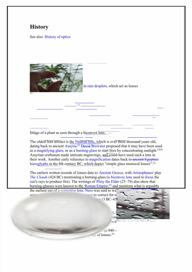
The Golden Gate Bridge refracted in rain droplets, which act as lenses
Image of a plant as seen through a biconvex lens.
The oldest lens artifact is the Nimrud lens, which is over three thousand years old,dating back to ancient Assyria.[3] David Brewster proposed that it may have been used
as a magnifying glass, or as a burning-glass to start fires by concentrating sunlight.[3][4]
Assyrian craftsmen made intricate engravings, and could have used such a lens in
their work. Another early reference to magnification dates back to ancient Egyptian
hieroglyphs in the 8th century BC, which depict "simple glass meniscal lenses".[5]
The earliest written records of lenses date to Ancient Greece, with Aristophanes' play
The Clouds (424 BC) mentioning a burning-glass (a biconvex lens used to focus the
sun's rays to produce fire). The writings of Pliny the Elder (23–79) also show that
burning-glasses were known to the Roman Empire,[6] and mentions what is arguably
the earliest use of a corrective lens: Nero was said to watch the gladiatorial games using an emerald[7] (presumably concave to correct for myopia, though the reference
is vague). Both Pliny and Seneca the Younger (3 BC–65) described the magnifying
effect of a glass globe filled with water .
The word lens comes from the Latin name of the lentil, because a double-convex lens
is lentil-shaped. The genus of the lentil plant is Lens, and the most commonly eaten
species is Lens culinaris. The lentil plant also gives its name to a geometric figure.
The Arab physicist and mathematician Ibn Sahl (c.940–c.1000) used what is now
known as Snell's law to calculate the shape of lenses.[8]

8/8/2019 Lens (Optics)
http://slidepdf.com/reader/full/lens-optics 5/15
Excavations at the Viking harbour town of Fröjel, Gotland, Sweden discovered in
1999 the rock crystal Visby lenses, produced by turning on pole-lathes at Fröjel in the
11th to 12th century, with an imaging quality comparable to that of 1950s aspheric
lenses. The Viking lenses concentrate sunlight enough to ignite fires.
Widespread use of lenses did not occur until the use of reading stones in the 11thcentury and the invention of spectacles, probably in Italy in the 1280s. Scholars have
noted that spectacles were invented not long after the translation of Ibn al-Haytham's
Book of Optics into Latin, but it is not clear what role, if any, the optical theory of the
time played in the discovery.[5][9] Nicholas of Cusa is believed to have been the first to
discover the benefits of concave lenses for the treatment of myopia in 1451.
The Abbe sine condition, due to Ernst Abbe (1860s), is a condition that must be
fulfilled by a lens or other optical system in order for it to produce sharp images of
off-axis as well as on-axis objects. It revolutionized the design of optical instruments
such as microscopes, and helped to establish the Carl Zeiss company as a leading
supplier of optical instruments.
Construction of simple lenses
Most lenses are spherical lenses: their two surfaces are parts of the surfaces of
spheres, with the lens axis ideally perpendicular to both surfaces. Each surface can be
convex (bulging outwards from the lens), concave (depressed into the lens), or planar (flat). The line joining the centres of the spheres making up the lens surfaces is called
the axis of the lens. Typically the lens axis passes through the physical centre of the
lens, because of the way they are manufactured. Lenses may be cut or ground after
manufacturing to give them a different shape or size. The lens axis may then not passthrough the physical centre of the lens.
Toric or sphero-cylindrical lenses have surfaces with two different radii of curvature
in two orthogonal planes. They have a different focal power in different meridians.
This is a form of deliberate astigmatism.
More complex are aspheric lenses. These are lenses where one or both surfaces have a
shape that is neither spherical nor cylindrical. Such lenses can produce images with
much less aberration than standard simple lenses.
Types of simple lenses

8/8/2019 Lens (Optics)
http://slidepdf.com/reader/full/lens-optics 6/15
Lenses are classified by the curvature of the two optical surfaces. A lens is biconvex(or double convex, or just convex) if both surfaces are convex. If both surfaces have
the same radius of curvature, the lens is equiconvex. A lens with two concave surfaces
is biconcave (or just concave). If one of the surfaces is flat, the lens is plano-convexor plano-concave depending on the curvature of the other surface. A lens with one
convex and one concave side is convex-concave or meniscus. It is this type of lensthat is most commonly used in corrective lenses.
If the lens is biconvex or plano-convex, a collimated or parallel beam of light
travelling parallel to the lens axis and passing through the lens will be converged (or
focused ) to a spot on the axis, at a certain distance behind the lens (known as the
focal length). In this case, the lens is called a positive or converging lens.
If the lens is biconcave or plano-concave, a collimated beam of light passing through
the lens is diverged (spread); the lens is thus called a negative or diverging lens. The
beam after passing through the lens appears to be emanating from a particular point
on the axis in front of the lens; the distance from this point to the lens is also known
as the focal length, although it is negative with respect to the focal length of a
converging lens.

8/8/2019 Lens (Optics)
http://slidepdf.com/reader/full/lens-optics 7/15
Convex-concave (meniscus) lenses can be either positive or negative, depending on
the relative curvatures of the two surfaces. A negative meniscus lens has a steeper
concave surface and will be thinner at the centre than at the periphery. Conversely, a
positive meniscus lens has a steeper convex surface and will be thicker at the centre
than at the periphery. An ideal thin lens with two surfaces of equal curvature would
have zero optical power , meaning that it would neither converge nor diverge light. All
real lenses have a nonzero thickness, however, which affects the optical power. To
obtain exactly zero optical power, a meniscus lens must have slightly unequal
curvatures to account for the effect of the lens' thickness.
Lensmaker's equation
The focal length of a lens in air can be calculated from the lensmaker's equation:
where
f is the focal length of the lens,
n is the refractive index of the lens material, R1 is the radius of curvature of the lens surface closest to the light source,
R2 is the radius of curvature of the lens surface farthest from the light source,
and
d is the thickness of the lens (the distance along the lens axis between the two
surface vertices).
Sign convention of lens radii R1 and R2
Main article: Radius of curvature (optics)
The signs of the lens' radii of curvature indicate whether the corresponding surfacesare convex or concave. The sign convention used to represent this varies, but in this

8/8/2019 Lens (Optics)
http://slidepdf.com/reader/full/lens-optics 8/15
article if R1 is positive the first surface is convex, and if R1 is negative the surface is
concave. The signs are reversed for the back surface of the lens: if R2 is positive the
surface is concave, and if R2 is negative the surface is convex. If either radius is
infinite, the corresponding surface is flat. With this convention the signs are
determined by the shapes of the lens surfaces, and are independent of the direction in
which light travels through the lens.
Thin lens equation
If d is small compared to R1 and R2, then the thin lens approximation can be made.
For a lens in air, f is then given by
[11]
The focal length f is positive for converging lenses, and negative for diverging lenses.The reciprocal of the focal length, 1/ f , is the optical power of the lens. If the focal
length is in metres, this gives the optical power in dioptres (inverse metres).
Lenses have the same focal length when light travels from the back to the front as
when light goes from the front to the back, although other properties of the lens, such
as the aberrations are not necessarily the same in both directions.
Imaging properties
This image has three visible reflections and one visible projection of the same lamp;
two reflections are on a biconvex lens.
As mentioned above, a positive or converging lens in air will focus a collimated beamtravelling along the lens axis to a spot (known as the focal point) at a distance f from
the lens. Conversely, a point source of light placed at the focal point will be converted
into a collimated beam by the lens. These two cases are examples of image formation
in lenses. In the former case, an object at an infinite distance (as represented by a
collimated beam of waves) is focused to an image at the focal point of the lens. In the
latter, an object at the focal length distance from the lens is imaged at infinity. The
plane perpendicular to the lens axis situated at a distance f from the lens is called the
focal plane.

8/8/2019 Lens (Optics)
http://slidepdf.com/reader/full/lens-optics 9/15
If the distances from the object to the lens and from the lens to the image are S 1 and S 2respectively, for a lens of negligible thickness, in air, the distances are related by the
thin lens formula
.
This can also be put into the "Newtonian" form:
[12]
where x1 = S 1 − f and x2 = S 2 − f .
What this means is that, if an object is placed at a distance S 1 along the axis in front of
a positive lens of focal length f , a screen placed at a distance S 2 behind the lens will
have a sharp image of the object projected onto it, as long as S 1 > f (if the lens-to-
screen distance S 2 is varied slightly, the image will become less sharp). This is the
principle behind photography and the human eye. The image in this case is known as
a real image.

8/8/2019 Lens (Optics)
http://slidepdf.com/reader/full/lens-optics 10/15
Note that if S 1 < f , S 2 becomes negative, the image is apparently positioned on the
same side of the lens as the object. Although this kind of image, known as a virtual image, cannot be projected on a screen, an observer looking through the lens will see
the image in its apparent calculated position. A magnifying glass creates this kind of
image.
The magnification of the lens is given by:
,
where M is the magnification factor; if |M |>1, the image is larger than the object.
Notice the sign convention here shows that, if M is negative, as it is for real images,
the image is upside-down with respect to the object. For virtual images, M is positive
and the image is upright.
In the special case that S 1 = ∞, then S 2 = f and M = − f / ∞ = 0. This corresponds to a
collimated beam being focused to a single spot at the focal point. The size of the
image in this case is not actually zero, since diffraction effects place a lower limit on
the size of the image (see Rayleigh criterion).
The formulas above may also be used for negative (diverging) lens by using anegative focal length ( f ), but for these lenses only virtual images can be formed.
For the case of lenses that are not thin, or for more complicated multi-lens optical
systems, the same formulas can be used, but S 1 and S 2 are interpreted differently. If
the system is in air or vacuum, S 1 and S 2 are measured from the front and rear
principal planes of the system, respectively. Imaging in media with an index of
refraction greater than 1 is more complicated, and is beyond the scope of this article.

8/8/2019 Lens (Optics)
http://slidepdf.com/reader/full/lens-optics 11/15
Aberrations
Lenses do not form perfect images, and there is always some degree of distortion or aberration introduced by the lens which causes the image to be an imperfect replica
of the object. Careful design of the lens system for a particular application ensures
that the aberration is minimized. There are several different types of aberration which
can affect image quality.
Spherical aberration
Spherical aberration occurs because spherical surfaces are not the ideal shape with
which to make a lens, but they are by far the simplest shape to which glass can be
ground and polished and so are often used. Spherical aberration causes beams parallel
to, but distant from, the lens axis to be focused in a slightly different place than beams
close to the axis. This manifests itself as a blurring of the image. Lenses in which
closer-to-ideal, non-spherical surfaces are used are called aspheric lenses. These were
formerly complex to make and often extremely expensive, but advances in
technology have greatly reduced the manufacturing cost for such lenses. Spherical
aberration can be minimised by careful choice of the curvature of the surfaces for a
particular application: for instance, a plano-convex lens which is used to focus a
collimated beam produces a sharper focal spot when used with the convex side
towards the beam source.
Coma
Another type of aberration is coma, which derives its name from the comet-like
appearance of the aberrated image. Coma occurs when an object off the optical axis
of the lens is imaged, where rays pass through the lens at an angle to the axis θ. Rays
which pass through the centre of the lens of focal length f are focused at a point with
distance f tan θ from the axis. Rays passing through the outer margins of the lens are
focused at different points, either further from the axis (positive coma) or closer to the
axis (negative coma). In general, a bundle of parallel rays passing through the lens at
a fixed distance from the centre of the lens are focused to a ring-shaped image in the

8/8/2019 Lens (Optics)
http://slidepdf.com/reader/full/lens-optics 12/15
focal plane, known as a comatic circle. The sum of all these circles results in a V-
shaped or comet-like flare. As with spherical aberration, coma can be minimised (and
in some cases eliminated) by choosing the curvature of the two lens surfaces to match
the application. Lenses in which both spherical aberration and coma are minimised
are called bestform lenses.
Chromatic aberration
Chromatic aberration is caused by the dispersion of the lens material—the variation
of its refractive index, n, with the wavelength of light. Since, from the formulae
above, f is dependent upon n, it follows that different wavelengths of light will be
focused to different positions. Chromatic aberration of a lens is seen as fringes of
colour around the image. It can be minimised by using an achromatic doublet (or achromat ) in which two materials with differing dispersion are bonded together to
form a single lens. This reduces the amount of chromatic aberration over a certain
range of wavelengths, though it does not produce perfect correction. The use of
achromats was an important step in the development of the optical microscope. An
apochromat is a lens or lens system which has even better correction of chromatic
aberration, combined with improved correction of spherical aberration. Apochromats
are much more expensive than achromats.
Different lens materials may also be used to minimise chromatic aberration, such as
specialised coatings or lenses made from the crystal fluorite. This naturally occurring
substance has the highest known Abbe number , indicating that the material has lowdispersion.

8/8/2019 Lens (Optics)
http://slidepdf.com/reader/full/lens-optics 13/15
Other types of aberration
Other kinds of aberration include field curvature , barrel and pincushion distortion,
and astigmatism.
Aperture diffraction
Even if a lens is designed to minimize or eliminate the aberrations described above,
the image quality is still limited by the diffraction of light passing through the lens'
finite aperture. A diffraction-limited lens is one in which aberrations have been
reduced to the point where the image quality is primarily limited by diffraction under the design conditions.
Compound lenses
See also: Photographic lens, Doublet (lens), and Achromat
Simple lenses are subject to the optical aberrations discussed above. In many cases
these aberrations can be compensated for to a great extent by using a combination of
simple lenses with complementary aberrations. A compound lens is a collection of
simple lenses of different shapes and made of materials of different refractive indices,arranged one after the other with a common axis.

8/8/2019 Lens (Optics)
http://slidepdf.com/reader/full/lens-optics 14/15
The simplest case is where lenses are placed in contact: if the lenses of focal lengths f 1and f 2 are "thin", the combined focal length f of the lenses is given by
Since 1/ f is the power of a lens, it can be seen that the powers of thin lenses in contact
are additive.
If two thin lenses are separated in air by some distance d (where d is smaller than the
focal length of the first lens), the focal length for the combined system is given by
The distance from the second lens to the focal point of the combined lenses is calledthe back focal length (BFL).
As d tends to zero, the value of the BFL tends to the value of f given for thin lenses in
contact.
If the separation distance is equal to the sum of the focal lengths (d = f 1+ f 2), the
combined focal length and BFL are infinite. This corresponds to a pair of lenses thattransform a parallel (collimated) beam into another collimated beam. This type of
system is called an afocal system, since it produces no net convergence or divergence
of the beam. Two lenses at this separation form the simplest type of optical telescope.
Although the system does not alter the divergence of a collimated beam, it does alter
the width of the beam. The magnification of such a telescope is given by
which is the ratio of the input beam width to the output beam width. Note the signconvention: a telescope with two convex lenses ( f 1 > 0, f 2 > 0) produces a negative
magnification, indicating an inverted image. A convex plus a concave lens ( f 1 > 0 > f 2)
produces a positive magnification and the image is upright.
Uses of lenses
A single convex lens mounted in a frame with a handle or stand is a magnifying glass.
Lenses are used as prosthetics for the correction of visual impairments such as
myopia, hyperopia, presbyopia, and astigmatism. (See corrective lens, contact lens,eyeglasses.) Most lenses used for other purposes have strict axial symmetry; eyeglass

8/8/2019 Lens (Optics)
http://slidepdf.com/reader/full/lens-optics 15/15
lenses are only approximately symmetric. They are usually shaped to fit in a roughly
oval, not circular, frame; the optical centers are placed over the eyeballs; their
curvature may not be axially symmetric to correct for astigmatism. Sunglasses' lenses
are designed to attenuate light; sunglass lenses that also correct visual impairments
can be custom made.
Other uses are in imaging systems such as monoculars, binoculars, telescopes,
microscopes, cameras and projectors. Some of these instruments produce a virtual
image when applied to the human eye; others produce a real image which can be
captured on photographic film or an optical sensor , or can be viewed on a screen. In
these devices lenses are sometimes paired up with curved mirrors to make a
catadioptric system where the lenses spherical aberration corrects the opposite
aberration in the mirror (such as Schmidt and meniscus correctors).
Convex lenses produce an image of an object at infinity at their focus; if the sun is
imaged, much of the visible and infrared light incident on the lens is concentrated into
the small image. A large lens will create enough intensity to burn a flammable objectat the focal point. Since ignition can be achieved even with a poorly made lens, lenses
have been used as burning-glasses for at least 2400 years.[13] A modern application is
the use of relatively large lenses to concentrate solar energy on relatively small
photovoltaic cells, harvesting more energy without the need to use larger, more
expensive, cells.
Radio astronomy and radar systems often use dielectric lenses, commonly called a
lens antenna to refract electromagnetic radiation into a collector antenna.
Lenses can become scratched and abraded. Abrasion resistant coatings are availableto help control this.