lensless, ultra-wideband fiber optic rotary joint for...
TRANSCRIPT
Lensless, ultra-wideband fiber optic rotaryjoint for biomedical applicationsWIHAN KIM, XI CHEN, JAVIER A. JO, AND BRIAN E. APPLEGATE*Department of Biomedical Engineering, Texas A&M University, College Station, Texas 77843, USA*Corresponding author: [email protected]
Received 17 February 2016; revised 25 March 2016; accepted 30 March 2016; posted 1 April 2016 (Doc. ID 259563); published 20 April 2016
The demands of optical fiber-based biomedical applicationscan, in many cases, outstrip the capabilities of lens-basedcommercially available fiber optic rotary joints. In some cir-cumstances, it is necessary to use very broad spectral band-widths (near UV to short-wave IR) and specialized opticalfibers, such as double-clad fiber, and have the capacity to ac-commodate high rotational velocities. The broad spectrum,stretching down into the UV, presents two problems: (1) ad-equate chromatic correction in the lenses across the entirebandwidth and (2) strong UV absorption by the fluids usedto lubricate the rotary joint. To accommodate these types ofapplications, we have developed an ultra-wideband lenslessfiber optic rotary joint based on the principle that whentwo optical fibers are coaligned and placed in contact (orvery close), the optical losses at the junction are very low.The advances demonstrated here enable excellent perfor-mance (<0.2 dB insertion loss), even down into the UV andspanning a wavelength range of at least 355–1360 nm withsingle-mode, multimode, and double-clad fibers. We alsodemonstrate excellent performance, ∼0.38 dB insertion loss,at rotational velocities up to 8800 rpm (146 Hz). To the bestof our knowledge, this is the first demonstration of this typeof rotary joint capable of such a wide bandwidth and highrotational velocities. © 2016 Optical Society of America
OCIS codes: (060.2330) Fiber optics communications; (060.2360)
Fiber optics links and subsystems; (060.2430) Fibers, single-mode.
http://dx.doi.org/10.1364/OL.41.001973
Fiber optic rotary joints (FORJ) are widely used for transmit-ting optical signals, where one side of a fiber junction must befreely rotating. Numerous fields take advantage of these devices,e.g., light communication through robotic joints, radar antennabased on slip-ring housings for satellite communication sys-tems, military radar, and civil radar [1–3]. In particular, weare motivated by applications in medical imaging and sensing,where it is sometimes necessary to use very broad spectralbandwidths, near UV to short-wave IR [4], as well as more spe-cialized optical fibers such as double-clad fiber [5]. These con-ditions are very challenging for the current set of commerciallyavailable FORJ that use lenses in their optical design. Thebroad spectral bandwidth requires management of chromatic
aberration in the lenses, thus making it difficult and potentiallyvery expensive to design and construct a high-performancelens-based FORJ. Likewise, good performance at short wave-lengths requires a judicious choice of lubricants, since manytypical lubricants have strong UV absorption that can lead todegradation of the lubricant, thermal damage to the optics, andunwanted background fluorescence. Specialized fibers, such asdouble-clad fibers, pose additional challenges, e.g., maintainingthe modal integrity of the light as it passes through the rotaryjunction and accommodating the different numerical aperturesof the single-mode and multimode cores.
In particular, we are interested in developing technologiesfor intravascular optical imaging in arteries using catheter endo-scopes. This is most frequently accomplished by rotating theendoscope at high speed while pulling the endoscope back.This creates a spiral image of the artery. The artery must beflushed with a transparent fluid during imaging to clear theblood. This introduces an additional challenge peculiar to ourapplication—short bursts of rapid rotation of the FORJ atvelocities exceeding 6000 rpm for a time duration of 4–6 s.The high rotational velocity is required due to the maximumvolume/time allowed for the flush to ensure patient safety. Thisis, in fact, how commercial intravascular optical coherencetomography (OCT) systems function. We have been workingtoward developing multimodal systems [6], integrating OCTwith fluorescence lifetime imaging microscopy (FLIM) [7] tocharacterize atherosclerotic plaques [8,9] and garner informationthat has previously only been available in postmortem histopa-thology. Extending this multimodal approach to intravascular im-aging invokes all of the requirements enumerated above for theFORJ, i.e., extremely broad bandwidth, high rotational velocity,and maintenance of modal integrity with a double-clad fiber.
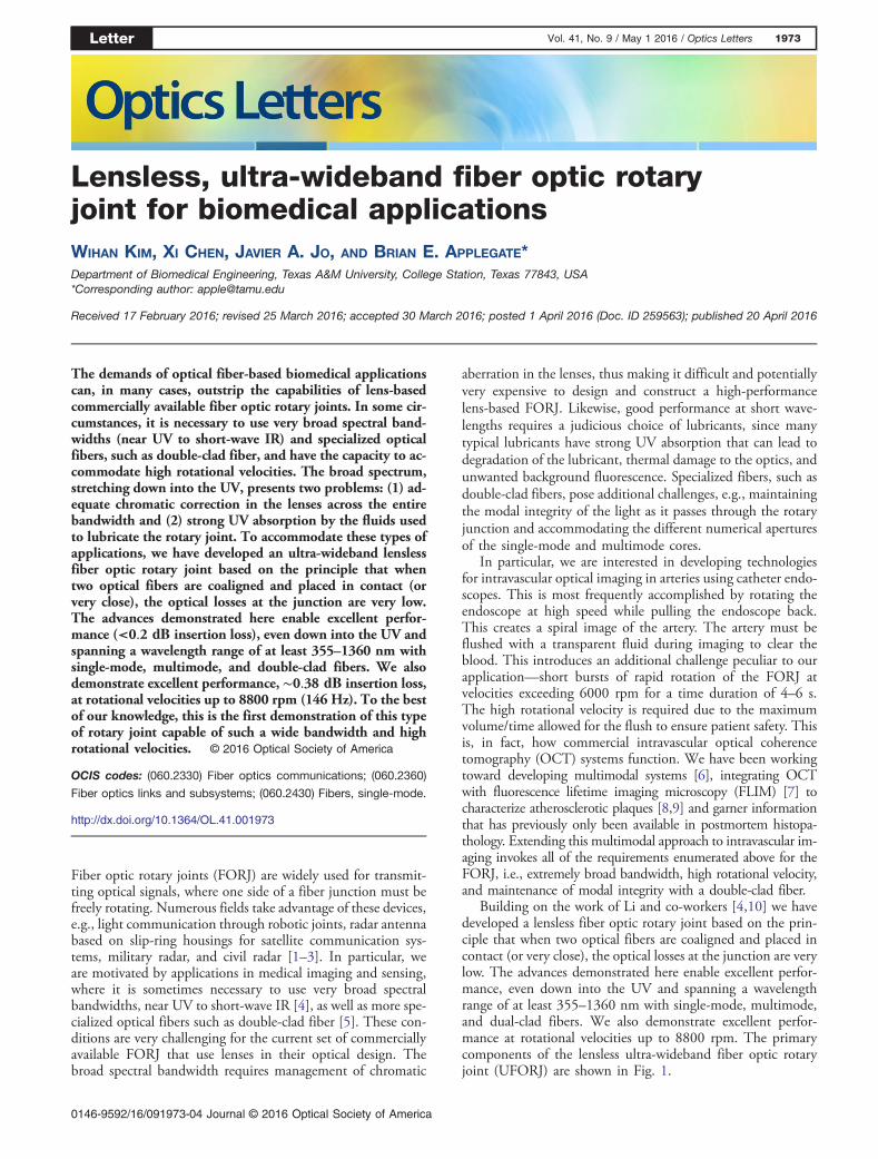
Building on the work of Li and co-workers [4,10] we havedeveloped a lensless fiber optic rotary joint based on the prin-ciple that when two optical fibers are coaligned and placed incontact (or very close), the optical losses at the junction are verylow. The advances demonstrated here enable excellent perfor-mance, even down into the UV and spanning a wavelengthrange of at least 355–1360 nm with single-mode, multimode,and dual-clad fibers. We also demonstrate excellent perfor-mance at rotational velocities up to 8800 rpm. The primarycomponents of the lensless ultra-wideband fiber optic rotaryjoint (UFORJ) are shown in Fig. 1.
Letter Vol. 41, No. 9 / May 1 2016 / Optics Letters 1973
0146-9592/16/091973-04 Journal © 2016 Optical Society of America
A fiber chuck (FPH-J, Newport) was assembled with two pil-low-mounted bearings and a bore diameter (ϕ � 3.175 mm)pulley to hold the rotating portion of fiber. The fiber chuckcould accommodate bare fibers up to 250 μm in diameter. Anelectric motor (RE50, Maxon Motor) fitted with a bore diameterpulley (ϕ � 8 mm) was coupled to the fiber chuck via a pulleybelt. The gear ratio and maximum rotation velocity of the loadedelectric motor resulted in a maximum UFORJ rotational velocityof 8800 rpm. A short fiber patch cable connectorized on one sidewas placed in the fiber chuck and secured via a customized fit-ting. The connectorized end allows for easy substitution of fibercomponents on the rotating portion of the optical system, in ourcase, a fiber endoscope. The bare, cleaved, end of the patch cablewas held by the fiber chuck and inserted into one side of a glassferrule (FER-1.8-126-GL,OZOptics) whose diameter (126 μm)was chosen to closely match the diameter of the bare fiber afterremoval of the buffer. The ferrule had conical shaped ends onboth sides that tapered down to the inner ferrule diameter. Thisenabled easy damage free insertion of bare fiber on either end.
The glass ferrule did not rotate and was attached to a customfitting held in an x, y, z adjustment mount. The x, y, z mountallowed for careful alignment of the glass ferrule to the fiberchuck. The nonrotating fiber was passed through the oppositeend of the glass ferrule and butted up against the fiber held inthe fiber chuck. Both fibers were cleaved before being insertedinto the glass ferrule. The nonrotating fiber was bonded to theferrule with epoxy. The glass ferrule was filled with lubricatingfluid which served several purposes. It reduced reflections fromthe cleaved fibers and provided lubrication for the rotatingfiber. It also enabled greater separation of the two fibers whilemaintaining good coupling efficiency.
First, we set out to determine the suitability of potentialindex matching fluids to cover the requisite bandwidth,355–1360 nm. In addition to being transparent over this range,the index matching fluid was ideally chosen to minimize inser-tion loss due to reflections from, and separation between, thetwo fiber end faces. Losses due to both sources as a function ofrefractive index (n) and fiber separation (Z 0) have been derivedpreviously [11,12] and are given by
Lref � −10 log
�1 −
� �n1 − n2��n1 � n2�
�2�; (1)
LSMF � 8.686 ln
�1� 1
2
�λZ 0
πn2w20
�2�; (2)
LMMF � −10 log
�1 −
Z 0NA
2n2r1
�; (3)
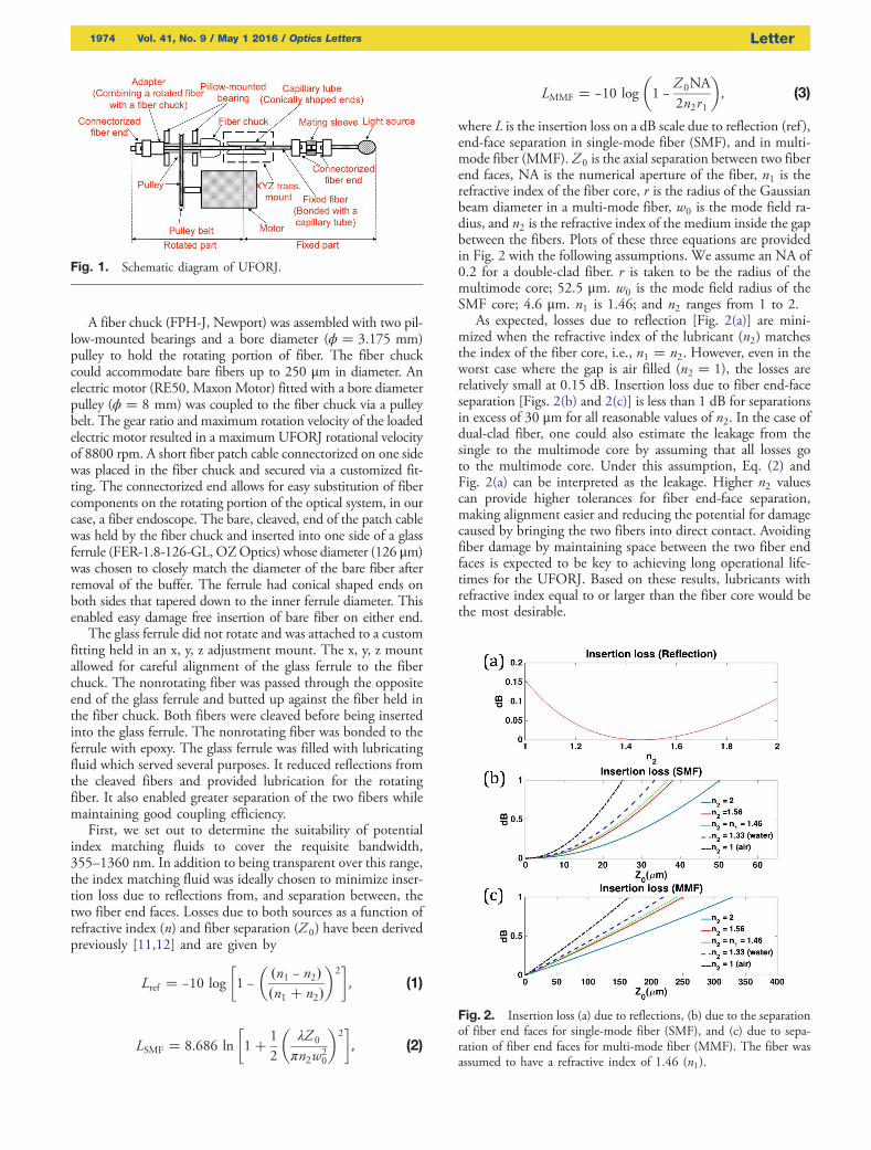
where L is the insertion loss on a dB scale due to reflection (ref ),end-face separation in single-mode fiber (SMF), and in multi-mode fiber (MMF). Z 0 is the axial separation between two fiberend faces, NA is the numerical aperture of the fiber, n1 is therefractive index of the fiber core, r is the radius of the Gaussianbeam diameter in a multi-mode fiber, w0 is the mode field ra-dius, and n2 is the refractive index of the medium inside the gapbetween the fibers. Plots of these three equations are providedin Fig. 2 with the following assumptions. We assume an NA of0.2 for a double-clad fiber. r is taken to be the radius of themultimode core; 52.5 μm. w0 is the mode field radius of theSMF core; 4.6 μm. n1 is 1.46; and n2 ranges from 1 to 2.
As expected, losses due to reflection [Fig. 2(a)] are mini-mized when the refractive index of the lubricant (n2) matchesthe index of the fiber core, i.e., n1 � n2. However, even in theworst case where the gap is air filled (n2 � 1), the losses arerelatively small at 0.15 dB. Insertion loss due to fiber end-faceseparation [Figs. 2(b) and 2(c)] is less than 1 dB for separationsin excess of 30 μm for all reasonable values of n2. In the case ofdual-clad fiber, one could also estimate the leakage from thesingle to the multimode core by assuming that all losses goto the multimode core. Under this assumption, Eq. (2) andFig. 2(a) can be interpreted as the leakage. Higher n2 valuescan provide higher tolerances for fiber end-face separation,making alignment easier and reducing the potential for damagecaused by bringing the two fibers into direct contact. Avoidingfiber damage by maintaining space between the two fiber endfaces is expected to be key to achieving long operational life-times for the UFORJ. Based on these results, lubricants withrefractive index equal to or larger than the fiber core would bethe most desirable.
Fig. 1. Schematic diagram of UFORJ.
Fig. 2. Insertion loss (a) due to reflections, (b) due to the separationof fiber end faces for single-mode fiber (SMF), and (c) due to sepa-ration of fiber end faces for multi-mode fiber (MMF). The fiber wasassumed to have a refractive index of 1.46 (n1).
1974 Vol. 41, No. 9 / May 1 2016 / Optics Letters Letter
We identified two potential lubricants, both with a refractiveindex of 1.52. The first was an index matching fluid (Norland105) with low viscosity, but unknown absorption spectrum andUV performance. The second was microscope objective immer-sion oil (Olympus, Type-F) with relatively high viscosity andmanufacturer-reported good performance in the UV. Using a365 nm light source (Mos-Cure mini 365, U-VIX), we madea qualitative measure of the fluorescence from the two candi-dates. The immersion oil had relatively low fluorescence emis-sion as reported by the manufacturer; however, emission fromthe index matching fluid was much stronger. Based on theseresults, we moved forward with only the immersion oil sincethe strong fluorescence from the index matching fluid wouldintroduce a strong background for fluorescence imaging.
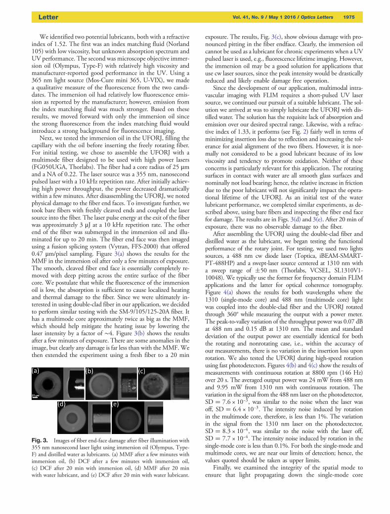
Next, we tested the immersion oil in the UFORJ, filling thecapillary with the oil before inserting the freely rotating fiber.For initial testing, we chose to assemble the UFORJ with amultimode fiber designed to be used with high power lasers(FG050UGA, Thorlabs). The fiber had a core radius of 25 μmand a NA of 0.22. The laser source was a 355 nm, nanosecondpulsed laser with a 10 kHz repetition rate. After initially achiev-ing high power throughput, the power decreased dramaticallywithin a few minutes. After disassembling the UFORJ, we notedphysical damage to the fiber end faces. To investigate further, wetook bare fibers with freshly cleaved ends and coupled the lasersource into the fiber. The laser pulse energy at the exit of the fiberwas approximately 3 μJ at a 10 kHz repetition rate. The otherend of the fiber was submerged in the immersion oil and illu-minated for up to 20 min. The fiber end face was then imagedusing a fusion splicing system (Vytran, FFS-2000) that offered0.47 μm/pixel sampling. Figure 3(a) shows the results for theMMF in the immersion oil after only a few minutes of exposure.The smooth, cleaved fiber end face is essentially completely re-moved with deep pitting across the entire surface of the fibercore. We postulate that while the fluorescence of the immersionoil is low, the absorption is sufficient to cause localized heatingand thermal damage to the fiber. Since we were ultimately in-terested in using double-clad fiber in our application, we decidedto perform similar testing with the SM-9/105/125-20A fiber. Ithas a multimode core approximately twice as big as the MMF,which should help mitigate the heating issue by lowering thelaser intensity by a factor of ∼4. Figure 3(b) shows the resultsafter a few minutes of exposure. There are some anomalies in theimage, but clearly any damage is far less than with theMMF.Wethen extended the experiment using a fresh fiber to a 20 min
exposure. The results, Fig. 3(c), show obvious damage with pro-nounced pitting in the fiber endface. Clearly, the immersion oilcannot be used as a lubricant for chronic experiments when a UVpulsed laser is used, e.g., fluorescence lifetime imaging. However,the immersion oil may be a good solution for applications thatuse cw laser sources, since the peak intensity would be drasticallyreduced and likely enable damage free operation.
Since the development of our application, multimodal intra-vascular imaging with FLIM requires a short-pulsed UV lasersource, we continued our pursuit of a suitable lubricant. The sol-ution we arrived at was to simply lubricate the UFORJ with dis-tilled water. The solution has the requisite lack of absorption andemission over our desired spectral range. Likewise, with a refrac-tive index of 1.33, it performs (see Fig. 2) fairly well in terms ofminimizing insertion loss due to reflection and increasing the tol-erance for axial alignment of the two fibers. However, it is nor-mally not considered to be a good lubricant because of its lowviscosity and tendency to promote oxidation. Neither of theseconcerns is particularly relevant for this application. The rotatingsurfaces in contact with water are all smooth glass surfaces andnominally not load bearing; hence, the relative increase in frictiondue to the poor lubricant will not significantly impact the opera-tional lifetime of the UFORJ. As an initial test of the waterlubricant performance, we completed similar experiments, as de-scribed above, using bare fibers and inspecting the fiber end facefor damage. The results are in Figs. 3(d) and 3(e). After 20 min ofexposure, there was no observable damage to the fiber.
After assembling the UFORJ using the double-clad fiber anddistilled water as the lubricant, we began testing the functionalperformance of the rotary joint. For testing, we used two lightssources, a 488 nm cw diode laser (Toptica, iBEAM-SMART-PT-488HP) and a swept-laser source centered at 1310 nm witha sweep range of �50 nm (Thorlabs, VCSEL, SL1310V1-10048). We typically use the former for frequency domain FLIMapplications and the latter for optical coherence tomography.Figure 4(a) shows the results for both wavelengths where the1310 (single-mode core) and 488 nm (multimode core) lightwas coupled into the double-clad fiber and the UFORJ rotatedthrough 360° while measuring the output with a power meter.The peak-to-valley variation of the throughput power was 0.07 dBat 488 nm and 0.15 dB at 1310 nm. The mean and standarddeviation of the output power are essentially identical for boththe rotating and nonrotating case, i.e., within the accuracy ofour measurements, there is no variation in the insertion loss uponrotation. We also tested the UFORJ during high-speed rotationusing fast photodetectors. Figures 4(b) and 4(c) show the results ofmeasurements with continuous rotation at 8800 rpm (146 Hz)over 20 s. The averaged output power was 24 mW from 488 nmand 9.95 mW from 1310 nm with continuous rotation. Thevariation in the signal from the 488 nm laser on the photodetector,SD � 7.6 × 10⁻³, was similar to the noise when the laser wasoff, SD � 6.4 × 10⁻³. The intensity noise induced by rotationin the multimode core, therefore, is less than 1%. The variationin the signal from the 1310 nm laser on the photodectector,SD � 8.3 × 10⁻⁴, was similar to the noise with the laser off,SD � 7.7 × 10⁻⁴. The intensity noise induced by rotation in thesingle-mode core is less than 0.1%. For both the single-mode andmultimode cores, we are near our limits of detection; hence, thevalues quoted should be taken as upper limits.
Finally, we examined the integrity of the spatial mode toensure that light propagating down the single-mode core
Fig. 3. Images of fiber end-face damage after fiber illumination with355 nm nanosecond laser light using immersion oil (Olympus, Type-F) and distilled water as lubricants. (a) MMF after a few minutes withimmersion oil, (b) DCF after a few minutes with immersion oil,(c) DCF after 20 min with immersion oil, (d) MMF after 20 minwith water lubricant, and (e) DCF after 20 min with water lubricant.
Letter Vol. 41, No. 9 / May 1 2016 / Optics Letters 1975

was not bleeding into the multimode core at the interface of thetwo fibers. Some imaging technologies, such as OCT, sufferfrom artifacts when executed with multimode fiber. Usingcommercial beam profilers (Thorlabs, BP104-VIS or IR), wemeasured the profile of the fiber output after the UFORJ fromlight launched in both the single-mode and multimode cores.The measurements were made while rotating the UFORJ at8800 rpm. The single-mode and multimode cores were illumi-nated with the 1310 and 488 nm light, respectively. The beamprofiler, either Vis or IR, was placed at a fixed distance from theoutput of the fiber with no optics between. Only the relativesize and shape of the two profiles have meaning. We expectedthat any significant coupling between the single-mode andmultimode core would appear as broadening at the base of anotherwise Gaussian looking profile from the single-mode core.
Figure 5 shows the results. We first note that there is no ap-parent change in the spatial mode, comparing the fixed androtating measurements from the single-mode. It is also apparentthat there is no significant shoulder on the profiles from thesingle-mode core that could be attributed to 1310 nm lightpropagating in the multimode core. While there must be someleakage into the multimode core, this evidence suggests that it issmall and beyond our current measurement technique.
We have begun using these UFORJ initially for intravascu-lar FLIM imaging. Our experience so far is that the operationallifetime of the UFORJ is at least sufficient for research pur-poses. The longest imaging session to date was 3 h with 22pullback images at rotational velocities of 2400–6000 rpm.At the end of the session, the UFORJ was still performing well.Given that the fiber end faces need not be in direct contact, weexpect that operational lifetimes can ultimately be made to rivalthose of standard commercial FORJ.
We have shown that a lensless fiber optic rotary joint, con-structed by butting the ends of a fixed and rotating bare fiber,can be made to operate over a broad spectral range with lowinsertion loss. Using distilled water as the lubricant and indexmatching fluid enabled operation down into the UV, at least to355 nm, and only limited by the absorption spectrum of waterand chromatic losses in the chosen fiber. The rotary joint couldalso be operated at high rotational velocities. It was tested up to8800 rpm. At this velocity, there is very little added intensitynoise due to rotational misalignment and no discernable changein the observed spatial mode of the 1310 nm light.
Funding. National Institutes of Health (NIH); NationalHeart, Lung, and Blood Institute (NHLBI) (1R01HL111361).
Acknowledgment. We would like to thank AnnaWisniowiecki for her help with the initial UFORJ design,and our funding source, National Institutes of Health/National Heart Lung and Blood Institute (NIH/NHLBI)(1R01HL111361).
REFERENCES
1. G. F. Dorsey, IEEE Trans. Compon. Hybrids Manuf. Technol. 5, 37(1982).
2. J. A. Speer and W. W. Koch, Proc. SPIE 0839, 122 (1987).3. S. Group, “Spotlight Rotating Solutions 2008–2015.”4. J. Xi, A. Zhang, Z. Liu, W. Liang, L. Y. Lin, S. Yu, and X. Li, Opt. Lett.
39, 2016 (2014).5. H. Yoo, J. W. Kim, M. Shishkov, E. Namati, T. Morse, R. Shubochkin,
J. R. McCarthy, V. Ntziachristos, B. E. Bouma, and F. A. Jaffer, Nat.Med. 17, 1680 (2011).
6. J. Park, J. A. Jo, S. Shrestha, P. Pande, Q. Wan, and B. E. Applegate,Biomed. Opt. Express 1, 186 (2010).
7. S. Shrestha, B. E. Applegate, J. Park, X. Xiao, P. Pande, and J. A. Jo,Opt. Lett. 35, 2558 (2010).
8. J. A. Jo, J. Park, P. Pande, S. Shrestha, M. J. Serafino, J. RicoJimenez Jde, F. Clubb, B. Walton, L. M. Buja, J. E. Phipps, M. D.Feldman, J. Adame, and B. E. Applegate, Eur. Heart J. Cardiovasc.Imaging 16, 910 (2015).
9. J. Park, P. Pande, S. Shrestha, F. Clubb, B. E. Applegate, and J. A.Jo, Atherosclerosis 220, 394 (2012).
10. X. Li, C. Chudoba, T. Ko, C. Pitris, and J. G. Fujimoto, Opt. Lett. 25,1520 (2000).
11. R. W. Gilsdorf and J. C. Palais, Appl. Opt. 33, 3440 (1994).12. D. K. Mynbaev and L. L. Scheiner, Fiber-Optic Communications
Technology (Prentice-Hall, 2001).
Fig. 4. Measured output power variation with rotation of UFORJ.(a) Step-wise rotation through one cycle; (b) continuous rotation at8800 rpm (146 Hz), 488 nm light coupled into the multimode core;and (c) continuous rotation at 8800 rpm (146 Hz), 1310 nm lightcoupled into the single-mode core.
Fig. 5. Measured beam profile from multimode (MM) and single-mode (SM) cores of the UFORJ while continuously rotating at8800 rpm and the single-mode core while fixed.
1976 Vol. 41, No. 9 / May 1 2016 / Optics Letters Letter