lenze frequency inverter 8200 vector user information · the frequency inverter 8200 vector...
TRANSCRIPT
Item # 608 655 87 December 2003 / Printed in Germany Rev. 1.02
Lenze Frequency Inverter 8200 vector User Information
December 2003 Lenze Frequency Inverter
2 Jetter AG
This document is to be used together with the appurtenant safety instructions. Apart from this document, the manuals, installation instructions and other documentation published by Lenze GmbH & Co KG for the products described herein have to be followed. Jetter AG reserves the right to make alterations to its products in the interest of technical progress. These alterations need not be documented in every single case. This manual and the information contained herein have been compiled with due diligence. However, Jetter AG assumes no liability for printing or other errors, as well as for damages arising from such errors. The brand names and product names used in this document are trademarks or registered trademarks of the respective title owner.

8200 vector User Information - December 2003
Jetter AG 3
Table of Contents
1 Introduction 5
1.1 About this Manual 5
1.2 Product Description 5
1.3 System Requirements 7
1.4 Technical Data 7
2 Installation 8
2.1 DIP Switch Settings 8
2.2 Connection to the System Bus 9
2.3 System Bus - Baud Rate 11
2.4 System Bus Cable 12
3 CANopen Services 13
4 Software and Programming 14
4.1 Register Areas 14
4.2 Register Addressing 14
4.3 Description of Registers 16
4.3.1 Status Word and Control Word 16 4.3.2 Setpoint Value and Actual Value 17 4.3.3 Diagnostics and Adminstration 19
4.4 Monitoring Interval 22
4.5 Process Data Synchronization 22
5 Diagnostic Indicators (LEDs) 23
A Index of Illustrations I

December 2003 Lenze Frequency Inverter
4 Jetter AG
History Revision 1.00 First edition
Revision 1.01 I/O sum has been corrected
Revision 1.02 Chapter "Combination of Modules" has been removed.
Chapter "Calculating the I/O Sum" has been removed.

8200 vector Introduction
Jetter AG 5
1 Introduction 1.1 About this Manual This user information ...
- gives a description on how to connect and commission frequency inverters of Lenze GmbH & Co KG connected to the Jetter AG system bus.
- is to be used along with the manuals on the used frequency inverter and Fieldbus function module published by Lenze GmbH & Co KG.
1.2 Product Description Frequency Inverter 8200 Vector
The frequency inverter 8200 vector produced by Lenze GmbH & Co KG is used to achieve electronic speed variation of AC motors. The combination of a frequency inverter and a Lenze brand gearbox motor or AC motor results in a variable speed drive with excellent drive characteristics. Additional features, such as compact design and high functionality, make the frequency inverter 8200 vector the ideal solution for nearly all applications, e.g. in the field of air conditioning or materials-handling technology, as well as industrial automation.
Fieldbus Function Module 2175 The Fieldbus Function Module 2175 is a component designed for the frequency inverter model 8200 vector. It is for connecting drive controllers directly to the Jetter brand system bus. The Fieldbus Function Module provides transparent access to process data contained in the drive controller directly from within the application program. The Fieldbus Function Module 2175 is plugged onto the frequency inverter 8200 vector.

December 2003 Lenze Frequency Inverter
6 Jetter AG
Software Tool "Global Device Control"
For configuring the frequency controller, the software tool "Global Device Control" developed by Lenze GmbH & Co KG is required. For communication between PC and the Fieldbus Function Module 2175, you will need a special adapter cable produced by Lenze GmbH & Co KG and referred to as EMF2173XXXX.
Note
When configuring the frequency inverter via "Global Device Control" there must be no connection between the Fieldbus Function Module 2175 and the Jetter controller. �

8200 vector Introduction
Jetter AG 7
1.3 System Requirements Frequency inverters 8200 vector with plugged on Fieldbus Function Module 2175 can directly be connected to the Jetter system bus. Jetter brand JX2-I/O modules, JX2-Slave expansion modules and Smart I/O JX-SIO connected to the system bus can also be operated simultaneously. The following table shows the minimum required software versions supporting operation of frequency inverters on the Jetter System Bus.
Software Versions of Controllers Controller Minimum Software Version
JX6-SB / JX6-SB-I V 2.10
JetControl JC24X V 3.10
Nano-B V 3.50
Nano-C V 3.50
Nano-D V 2.02
1.4 Technical Data The following technical data have to be taken into account when connecting a frequency inverter to the system bus.
Technical Data Maximum number of frequency inverters connected to the system bus
The maximum number of frequency inverters is limited by the maximum allowable I/O sum for the corresponding controller.
10
Number of I/Os Nano-B / Nano-C / Nano-D 8
JC 24X/ JX6-SB / JX6-SB-I 16
Supported Fieldbus Function Modules Type 2175, SW Version 1.0
Supported basic devices
For the exact type designation of the supported basic devices please refer to the operator's manual of the Fieldbus function module.
8201 – 8204
8211 – 8218
8221 – 8227
8241 – 8246
8200 vector
8200 vector, Cold plate

December 2003 Lenze Frequency Inverter
8 Jetter AG
2 Installation 2.1 DIP Switch Settings The DIP switch of the Fieldbus function module 2175 is for setting the address, baud rate and bus system. Through the address of the Fieldbus function module 2175 an I/O module number is assigned to the frequency inverter.
Note The addresses actually set on the Fieldbus function module 2175 correspond to the values 50 through 59. During commissioning, these values are readdressed to the module numbers 70 through 79 by the Jetter controller.
Setting Address Numbers via S1 … S6 Module # S1 ... S6 Module # S1 ... S6
70 1 2 3 4 5 6 7 8 9 10
75
1 2 3 4 5 6 7 8 9 10
71 1 2 3 4 5 6 7 8 9 10
76
1 2 3 4 5 6 7 8 9 10
72 1 2 3 4 5 6 7 8 9 10
77
1 2 3 4 5 6 7 8 9 10
73 1 2 3 4 5 6 7 8 9 10
78
1 2 3 4 5 6 7 8 9 10
74 1 2 3 4 5 6 7 8 9 10
79
1 2 3 4 5 6 7 8 9 10
Setting Baud Rates and Bus System via S7 … S10 Baud S7 ... S10 Baud S7 ... S10
1000k 1 2 3 4 5 6 7 8 9 10
250k
1 2 3 4 5 6 7 8 9 10
500k 1 2 3 4 5 6 7 8 9 10
125k
1 2 3 4 5 6 7 8 9 10
�
8200 vector Installation
Jetter AG 9
2.2 Connection to the System Bus
Pin 7
Pin 3
Pin 5
Pin 2
GND
CL
CH CAN_H
V-
CAN_L
1 2 3 4 24VOUTPUT
1
2
3
4
5
6
7
8
5 6 7 8 0VOUTPUT
24V
JX2-OD8Jetter
Pin 9 open
SHLD
Shield
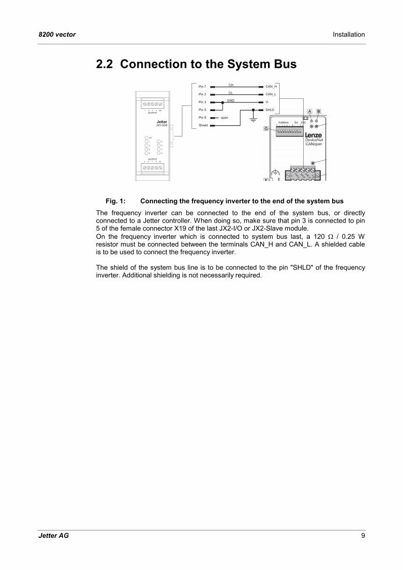
Fig. 1: Connecting the frequency inverter to the end of the system bus The frequency inverter can be connected to the end of the system bus, or directly connected to a Jetter controller. When doing so, make sure that pin 3 is connected to pin 5 of the female connector X19 of the last JX2-I/O or JX2-Slave module. On the frequency inverter which is connected to system bus last, a 120 � / 0.25 W resistor must be connected between the terminals CAN_H and CAN_L. A shielded cable is to be used to connect the frequency inverter. The shield of the system bus line is to be connected to the pin "SHLD" of the frequency inverter. Additional shielding is not necessarily required.

December 2003 Lenze Frequency Inverter
10 Jetter AG
Shield
Pin 7
Pin 1
Pin 3
Pin 5
Pin 2
Pin 4
GND
CL
CH
CMOD1
CMOD0
1 2 3 4 24VOUTPUT
1
2
3
4
5
6
7
8
5 6 7 8 0VOUTPUT
24V
JX2-OD8Jetter
Pin 9 open
Pin 7
Pin 1
Pin 3
Pin 2
Pin 4
24V
5V
0V 24VPOWER
JX2-PS1Jetter
CAN_H
V-
CAN_L
SHLD
Shield
Fig. 2: Connecting the frequency inverter via tap line When connecting the frequency inverter via tap line, jack X19 on the JX2-I/O or JX2-Slave module and connector X18 on the JX2-PS1 module have to be connected as shown above. As tap line leading to the frequency inverter a shielded cable is to be used. Make sure not to exceed the maximum tap line length. A tap line represents an open end of the system bus line. To reduce noise injection by the open end of the line, only one frequency inverter must be connected to each tap line. The shield of the system bus line is to be connected to the pin "SHLD" of the frequency inverter. Additional shielding is not necessarily required.

8200 vector Installation
Jetter AG 11
2.3 System Bus - Baud Rate The system bus of Jetter AG can be operated at baud rates between 125 kBaud and 1 MBaud. Generally, the max. permissible line length of the system bus becomes shorter with increasing baud rate. At the same time, however, the data transmission speed on the system bus increases with increasing baud rate. Whether the system bus is operated with max. data transmission speed or with long line length must be decided individually depending on the application. The permissible baud rates of the system bus also depend on the modules connected to it.
Permissible Baud Rates JX2-I/O Modules
JX2-Slave Modules Fieldbus Module
2175 125
kBaud 250
kBaud 500
kBaud 1000
kBaud
� � � � �
� � � � �
� � � �

December 2003 Lenze Frequency Inverter
12 Jetter AG
2.4 System Bus Cable The following minimum requirements apply to the manufacture of the system bus cable:
System Bus Cable - Technical Data Core cross-sectional area 1 MBaud 0.25 – 0.34 mm2
500 kBaud 0.34 – 0.50 mm2
250 kBaud 0.34 – 0.60 mm2
125 kBaud 0.50 – 0.60 mm2
Cable capacitance per unit length Maximum 60 pF / m
Resistivity 1 MBaud maximum 70 � / km
500 kBaud maximum 60 � / km
250 kBaud maximum 60 � / km
125 kBaud maximum 60 � / km
Number of cores 5
Shield Complete shielding, no paired shielding The maximum cable length depends on the baud rate used and on the number of modules connected to the bus. The following rule of thumb applies to the system bus cable: Each JX2-I/O module connected to the bus reduces the maximum cable length by approx. 1 m.
Allowed Line Lengths Baud Rate Max. line length Max. tap line
length Max. overall tap
line length
1000 kBaud 30 m 0.3 m 3 m
500 kBaud 100 m 1 m 39 m
250 kBaud 200 m 3 m 78 m
125 kBaud 200 m - - The potential difference between the controller and all expansion modules must not exceed 0.5 Volt. A constant ground potential must always be guaranteed. If there are long lines between two modules on the system bus, the line shield must be connected with functional earth (FE) approximately every 10 m because of EMI precautions. This connection should be laid out with the greatest possible surface area.

8200 vector CANopen Services
Jetter AG 13
3 CANopen Services The CANopen services referred to in this chapter are the sole responsibility of the relevant Jetter controller. Data that are transferred between frequency inverter and Jetter controller according to CANopen standard can directly be accessed via registers.
Network Management After power-up, the Jetter controller automatically starts frequency inverters connected to it. When doing so, the frequency inverter is put into the state "operational". The system bus module JX6-SB will commission expansion modules connected to it only after a command has been issued.
Node Guarding Protocol Jetter controllers monitor the connection to a frequency inverter in regular time intervals which can be set by the user (Node Guarding Protocol). If the controller does not receive a response from the frequency inverter, the controller issues a timeout error message. In addition to this, during Node Guarding the controller checks whether the frequency inverter is in "operational" state. If this is not the case, a timeout error message is issued, too. In both cases no exchange of process data between controller and frequency inverter will take place.
Parameter Data Channel The code places of the frequency inverter cannot be accessed by the Jetter controller via parameter data channel.
Process Data Channel The Jetter controller stores data of the process data channel to registers. Thus, the user has direct access to all data transferred via process data telegram. During commissioning of the frequency inverter, the Jetter controller sets the Lenze code place L-C0001 to "3", thus defining the process data channel as setpoint source.
Process Data Synchronization In adjustable time intervals, the Jetter controller broadcasts a SYNC telegram to all connected frequency inverters.
December 2003 Lenze Frequency Inverter
14 Jetter AG
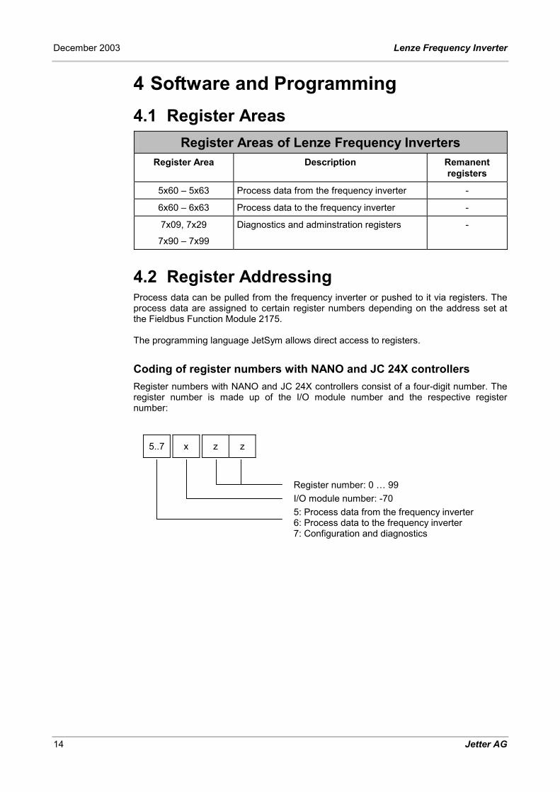
4 Software and Programming 4.1 Register Areas
Register Areas of Lenze Frequency Inverters Register Area Description Remanent
registers
5x60 – 5x63 Process data from the frequency inverter -
6x60 – 6x63 Process data to the frequency inverter -
7x09, 7x29
7x90 – 7x99
Diagnostics and adminstration registers -
4.2 Register Addressing Process data can be pulled from the frequency inverter or pushed to it via registers. The process data are assigned to certain register numbers depending on the address set at the Fieldbus Function Module 2175. The programming language JetSym allows direct access to registers.
Coding of register numbers with NANO and JC 24X controllers Register numbers with NANO and JC 24X controllers consist of a four-digit number. The register number is made up of the I/O module number and the respective register number:
5..7 x z z
Register number: 0 … 99 I/O module number: -70 5: Process data from the frequency inverter 6: Process data to the frequency inverter 7: Configuration and diagnostics

8200 vector Software and Programming
Jetter AG 15
Coding of register numbers with JX6-SB / JX6-SB-I modules JX6-SB register numbers consist of a seven-digit number. The register number is made up of the socket number, I/O module number and the respective register number: Throughout this document the four-digit register number for NANO, or JetControl 24X controllers is used. For applications with a JX6-SB / JX6-SB-I module, the number has to be preceded by the prefix "3m0".
3 m 0 5..7 x z z
Register number: 0 … 99 I/O module number: -70 5: Process data from the FI *) 6: Process data to the FI *) 7: Configuration and diagnostics Submodule socket: 1 ... 3
*) FI = Frequency Inverter

December 2003 Lenze Frequency Inverter
16 Jetter AG
4.3 Description of Registers 4.3.1 Status Word and Control Word
Register 5x60: Status Word of the Frequency InverterFunction Description
Read Lenze code place L-C0150 Present status word from the frequency inverter
Write Illegal
Value range 0 ... 65535
Value after reset Present state
Register 6x60: Control Word of the Frequency InverterFunction Description
Read Lenze code place L-C0135 Present control word from the frequency inverter
Write New control word to the frequency inverter
Value range 0 ... 65535
Value after reset 0
8200 vector Software and Programming
Jetter AG 17
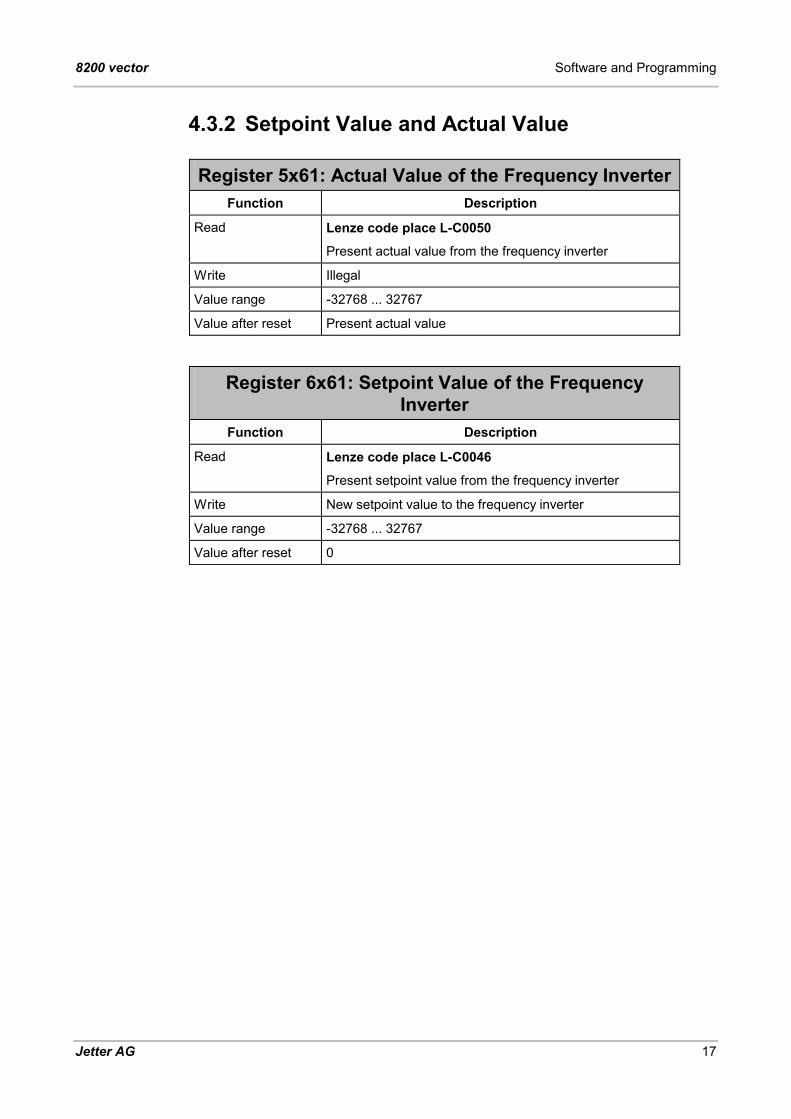
4.3.2 Setpoint Value and Actual Value
Register 5x61: Actual Value of the Frequency InverterFunction Description
Read Lenze code place L-C0050 Present actual value from the frequency inverter
Write Illegal
Value range -32768 ... 32767
Value after reset Present actual value
Register 6x61: Setpoint Value of the Frequency Inverter
Function Description
Read Lenze code place L-C0046 Present setpoint value from the frequency inverter
Write New setpoint value to the frequency inverter
Value range -32768 ... 32767
Value after reset 0
December 2003 Lenze Frequency Inverter
18 Jetter AG
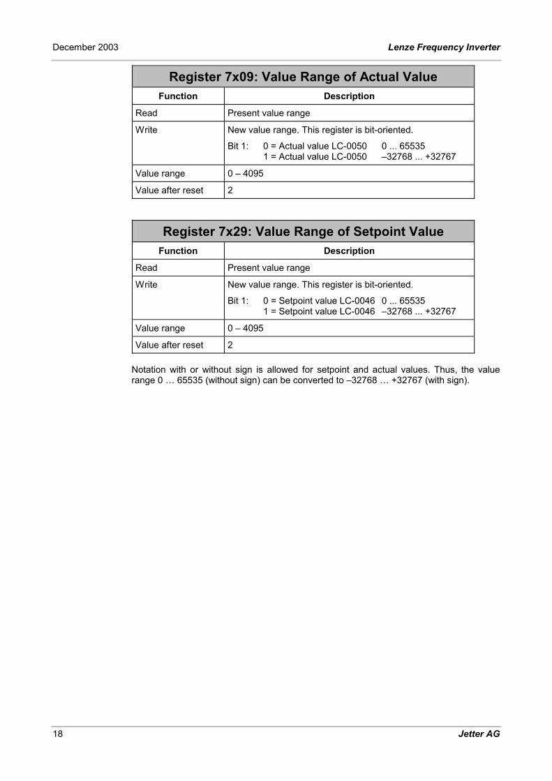
Register 7x09: Value Range of Actual Value Function Description
Read Present value range
Write New value range. This register is bit-oriented.
Bit 1: 0 = Actual value LC-0050 0 ... 65535 1 = Actual value LC-0050 –32768 ... +32767
Value range 0 – 4095
Value after reset 2
Register 7x29: Value Range of Setpoint Value Function Description
Read Present value range
Write New value range. This register is bit-oriented.
Bit 1: 0 = Setpoint value LC-0046 0 ... 65535 1 = Setpoint value LC-0046 –32768 ... +32767
Value range 0 – 4095
Value after reset 2 Notation with or without sign is allowed for setpoint and actual values. Thus, the value range 0 … 65535 (without sign) can be converted to –32768 … +32767 (with sign).

8200 vector Software and Programming
Jetter AG 19
4.3.3 Diagnostics and Adminstration The controllers produced by Jetter AG offer a host of registers designed for system bus administration and diagnostics. A detailed description of these registers is given in the documentation belonging to the corresponding controller. In general, Lenze frequency inverters are treated as Jetter brand Smart I/O JX-SIO modules.
Overview over System Bus Administration and Diagnostic Registers
Register Description
2008 System Bus Status
2011 I/O-Module Timeout
2012 Timeout of JX2-Slave Module
2013 Amount of I/O modules
2014 Amount of JX2-Slave Modules
2015 Index to Module Array
2016 Module array
2015 = 0 -> 2016 = Amount of modules
2015 = 1 -> 2016 = Code of the first module
2015 = 2 -> 2016 = Code of the second module
Code:
70 Lenze Frequency Inverter 8200 Vector
2029 System Bus Baud Rate
2070 Amount of JX-SIO modules
2071 Present I/O Size on the System Bus

December 2003 Lenze Frequency Inverter
20 Jetter AG
Register 7x90: Error Register Function Description
Read Present value of the fault register
Write Illegal
Value range 0 – 255
Value after reset 0 in faultless condition
Meaning of the error register bits Bit 0 : Error present
Register 7x92: Index to Error Array Function Description
Read Present index
Write New index
Value range 0 – 1
Value after reset 0
Register 7x93: Error Array Function Description
Read 7x92 = 0 -> 7x93 = Number of entries in the error array
7x92 = 1 -> 7x93 = Newest error
Write Illegal
Value range 32 bits, bit-oriented
Value after reset Number of entries in the error array
Meaning of the error array bits Bit 0..7 : Error register Bit 16..31 : Emergency code

8200 vector Software and Programming
Jetter AG 21
Register 7x97: Serial Number Function Description
Read Serial number
Write Illegal
Value range 32 bits
Value after reset Serial number
Register 7x99: Software Version Function Description
Read Software version
Write Illegal
Value range 24 bits or 32 bits
Value after reset Software version From this register the firmware version number of the frequency inverter can be read out. The value that has been read equals the product of the version number times a hundred. Thus, value 100, for example, refers to version 1.00.
December 2003 Lenze Frequency Inverter
22 Jetter AG
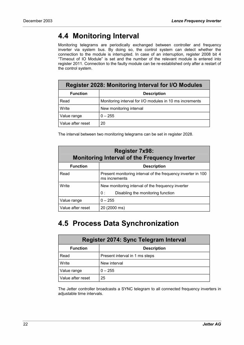
4.4 Monitoring Interval Monitoring telegrams are periodically exchanged between controller and frequency inverter via system bus. By doing so, the control system can detect whether the connection to the module is interrupted. In case of an interruption, register 2008 bit 4 “Timeout of IO Module” is set and the number of the relevant module is entered into register 2011. Connection to the faulty module can be re-established only after a restart of the control system.
Register 2028: Monitoring Interval for I/O Modules Function Description
Read Monitoring interval for I/O modules in 10 ms increments
Write New monitoring interval
Value range 0 – 255
Value after reset 20 The interval between two monitoring telegrams can be set in register 2028.
Register 7x98: Monitoring Interval of the Frequency Inverter
Function Description
Read Present monitoring interval of the frequency inverter in 100 ms increments
Write New monitoring interval of the frequency inverter
0 : Disabling the monitoring function
Value range 0 – 255
Value after reset 20 (2000 ms)
4.5 Process Data Synchronization
Register 2074: Sync Telegram Interval Function Description
Read Present interval in 1 ms steps
Write New interval
Value range 0 – 255
Value after reset 25 The Jetter controller broadcasts a SYNC telegram to all connected frequency inverters in adjustable time intervals.
8200 vector Diagnostic Indicators
Jetter AG 23
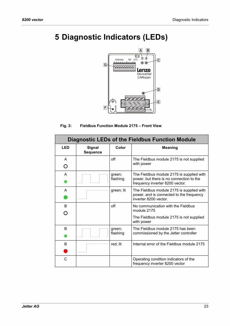
5 Diagnostic Indicators (LEDs)
Fig. 3: Fieldbus Function Module 2175 – Front View
Diagnostic LEDs of the Fieldbus Function Module LED Signal
Sequence Color Meaning
A
�
off The Fieldbus module 2175 is not supplied with power
A
�
green; flashing
The Fieldbus module 2175 is supplied with power, but there is no connection to the frequency inverter 8200 vector.
A
�
green; lit The Fieldbus module 2175 is supplied with power, and is connected to the frequency inverter 8200 vector.
B
�
off No communication with the Fieldbus module 2175
The Fieldbus module 2175 is not supplied with power
B
�
green; flashing
The Fieldbus module 2175 has been commissioned by the Jetter controller
B
�
red; lit Internal error of the Fieldbus module 2175
C Operating condition indicators of the frequency inverter 8200 vector


8200 vector Anhang
Jetter AG I
A. Index of Illustrations
Fig. 1: Frequency inverter connected to the end of the system bus 9 Fig. 2: Connecting a frequency inverter via tap line 10 Fig. 3: Fieldbus Function Module 2175 – Front View 23


Jetter AG
Gräterstrasse 2 D-71642 Ludwigsburg
Germany
Phone: +49 7141 2550-530 Phone Sales: +49 7141 2550-433 Fax: +49 7141 2550-484 Fax Sales: +49 7141 2550-484 Hotline: +49 7141 2550-444 Internet: http://www.jetter.de E-Mail: [email protected]
Jetter Subsidiaries
Jetter Asia Pte. Ltd. Jetter AG Switzerland Jetter Automation Inc.
32 Ang Mo Kio Industrial Park 2 #07-03 Sing Industrial Complex Singapore 569510
Münchwilerstrasse 19 CH-9554 Tägerschen
165 Ken Mar Industrial Parkway Broadview Heights OH 44147-2950
Singapore Switzerland U.S.A
Phone: +65 6483 8200 Fax: +65 6483 3881 E-Mail: [email protected]
Phone: +41 719 1879-50 Fax: +41 719 1879-69 E-Mail: [email protected]
Phone: +1 440 8380860 Fax: +1 440 8380861 E-Mail: [email protected]