leroy-somer d510c spannungsregler - handbuch … manual concerns the alternator a.v.r. which you...
TRANSCRIPT

=
˜=
˜ =
µC
PID
DSP
µP
X1 Z1 X2 Z2 B+ B-
U
V
W
IU
IV
IW
L1
L2
F+
USB
F-
CAN-H
CAN-L
PT100/CTP
PT100
PT100
DI1 DI2AI 1 AI 2
A.V.R.
D510 CInstallation and maintenance

2
2015.11 / jElectric Power Generation Installation and maintenance
D510 CA.V.R.
4243 en -
SAFETY MEASURES
Before using your machine for the first time, it is important to read the whole of this installation and maintenance manual.
All necessary operations and interventions on this machine must be performed by a qualified technician.
Our technical support service will be pleased to provide any additional infor-mation you may require.
The various operations described in this manual are accompanied by recommen-dations or symbols to alert the user to potential risks of accidents. It is vital that you understand and take notice of the following warning symbols.
Warning symbol for an operation capable of damaging or destroying the machine or surrounding equipment.
Warning symbol for general danger to personnel.
Warning symbol for electrical danger to personnel.
All servicing or repair operations performed on the AVR should be undertaken by personnel trained in the commissioning, servicing and main-tenance of electrical and mechanical components.
When the generator is driven at a frequency less than 28 Hz for more than 30 seconds with an analogic regulator, the AC power must be disconnected.
WARNINGThis A.V.R. can be incorporated in a machine marked C.E.This manual is be given to the end user.
© - We reserve the right to modify the characteristics of its products at any time in order to incorporate the latest technological developments. The informa-tion contained in this document may therefore be changed without notice.
This document may not be reproduced in any form without prior authorization.All brands and models have been registered and patents applied for.
WARNING
This manual concerns the alternator A.V.R. which you have just purchased.We wish to draw your attention to the contents of this maintenance manual.

3
2015.11 / jElectric Power Generation Installation and maintenance
D510 CA.V.R.
4243 en -
CONTENTS
1 - PRESENTATION ................................................................................................................51.1 - Operation .....................................................................................................................51.2 - Characteristics .............................................................................................................91.3 - Specifications ...............................................................................................................9
2 - HUMAN-MACHINE INTERFACE ..................................................................................... 112.1 - Communication .......................................................................................................... 112.2 - Analog I/O .................................................................................................................. 112.3 - Digital I/O ................................................................................................................... 112.4 - The LEDs ................................................................................................................... 112.5 - Wiring scheme ...........................................................................................................12
3 - SETTING THE FUNCTION PARAMETERS .....................................................................133.1 - Installation ..................................................................................................................133.2 - Startup .......................................................................................................................133.3 - Appearance ................................................................................................................133.4 - Configuration in customized mode .............................................................................42
4 - CONNECTION DIAGRAMS .............................................................................................46
5 - FAULT FLOW CHARTS ...................................................................................................47

4
2015.11 / jElectric Power Generation Installation and maintenance
D510 CA.V.R.
4243 en -
New functionalities:The table below describes the list of major changes on EasyReg 2.50 and the D510C firmware 2.20.
Softwares releases Evolutions
EasyReg 2.50
Possibility to modify the reactive power convention.Add of CAN check box to manage voltage bias through the CANBUS.Add of parameter to reset the Soft Start.Update of the alternators database.Improvement of the monitor when in PF regulation mode.Improvement of the management of the maximum excitation current in continuous operation.Improvement of the CT phase correction.
Firmware 2.20
Add of a control flag allowing to manage the voltage bias signal comes which can come from the CAN BUS or the remote analog input.Improvement of Stator current measurement and current limitation.Improvement of Grid code function.Improvement of temperature measurement through PT100Add of a parameter to reset the Soft Start function.
5
2015.11 / jElectric Power Generation Installation and maintenance
D510 CA.V.R.
4243 en -
1 - PRESENTATION
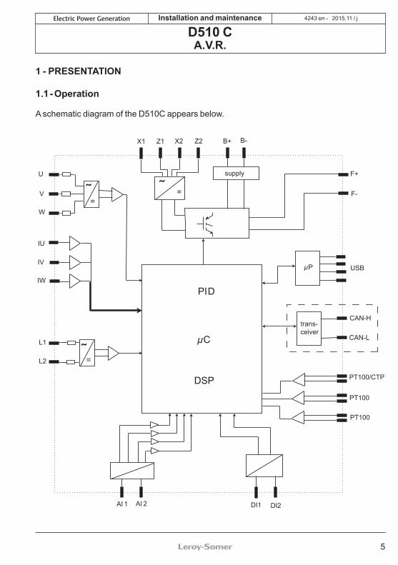
1.1 - Operation
A schematic diagram of the D510C appears below.
=
˜=
˜ =
µC
PID
DSP
trans-ceiver
µP
X1 Z1 X2 Z2 B+ B-
U
V
W
IU
IV
IW
L1
L2
F+
USB
F-
CAN-H
CAN-L
PT100/CTP
PT100
PT100
DI1 DI2AI 1 AI 2
supply
6
2015.11 / jElectric Power Generation Installation and maintenance
D510 CA.V.R.
4243 en -
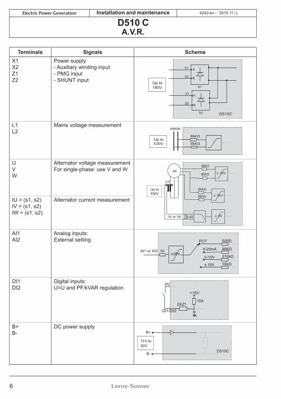
Terminals Signals SchemeX1X2Z1Z2
Power supply- Auxiliary winding input- PMG input- SHUNT input
D510C
X1 A
B
b1
b2
A
B
X2
Z1
Z2
Up to180V
L1L2
Mains voltage measurement
8MΩ
8MΩ
MAIN
Up to530V
UVW
Alternator voltage measurementFor single-phase: use V and W Alt
8MΩ
8MΩ
8MΩ
8MΩ
CT
1A or 5A 0.02 ± 5V
± 15V
± 15V
Up to530V
IU = (s1, s2)IV = (s1, s2)IW = (s1, s2)
Alternator current measurement
AI1AI2
Analog inputs:External setting POT
4-20mA
0-10V
± 10V
AI1 or AI2
500Ω
866Ω
210kΩ
10kΩ
±26V10
DI1DI2
Digital inputs:U=U and PF/kVAR regulation
DI1/DI22k21
+15V
0V
10k
B+B-
DC power supplyB+
B-
11V to30V
D510C

7
2015.11 / jElectric Power Generation Installation and maintenance
D510 CA.V.R.
4243 en -
Terminals Signals SchemeF+F-
Field excitation: 6 Aup to 15 A/10 s F+
F- Exciter
CTP
PT100_1PT100_2PT100-3
Temperature sensors
± 5V4k75
PT100 - CTP
+5V
100nF
CAN_HCAN_L CAN BUS
µ PCAN
Transceiver
H
L
USB_D+USB_D-
USB 2.0 communication port
µ PUSB
Controller
D-D+
+5V
0V
8
2015.11 / jElectric Power Generation Installation and maintenance
D510 CA.V.R.
4243 en -
• Power: It varies according to the type of field excitation (3 types).
- AREP: The AVR is powered by two auxiliary windings which are independent of the voltage sensing circuit.The first winding has a voltage in proportion with that of the alternator and the second has a voltage in proportion with the stator current.
- PMG: A permanent magnet generator (PMG) added to the alternator supplies the AVR with voltage which is independent of the main alternator winding.
- SHUNT: The AVR is powered by the main winding (140 V – 50/60 Hz).
Two fuses 10A/250VAC, Ref. Mersen: E084414P - MI6SA25V10/50 or
equivalent, mounted externally of the D510C must be used in the three types of excitation.
• Battery: This is used to supply the AVR with between 11 V and 30 V. It must always be present.
The battery supply must be protected by a 1 A Ref. Mersen :
A217028Q - GDL1 or equivalent fuse.
• Mains: This input is dedicated to the measure phase-to-phase mains voltage which will be taken as the reference when voltage matching is performed.
• Alternator voltage: This input measures the alternator output voltage to the AVR in:- three-phase (U, V, W)- single-phase (V, W)
• Current transformer(s): This input measures the current supplied by the alternator. It must always be present when the alternator is running in parallel operation or at PF or KVAR regulation or stator current limitation.
• The possible configurations are:- 1 CT on phase U- 3 CTs on phases U, V and W
• Temperature sensor(s): These are used to measure the alternator temperature and alert the user if there is a rise in temperature. This measurement can be taken either with 1 PTC or 3 PT100s.
• Communication:- USB port: This is used to connect the AVR to a computer and creates the link between the EasyReg software and the D510C.
- CAN port: This is used to connect the AVR to a bus CAN interpreter in order to exchange parameters with the D510C.
• I/O: This part is used to:- Enter settings - Send information from the D510C- Receive information from the alternator
• LEDs: These light-emitting diodes inform the user whether the AVR is working correctly or not.

9
2015.11 / jElectric Power Generation Installation and maintenance
D510 CA.V.R.
4243 en -
1.2 - CharacteristicsThe different functions of the D510C are:- Voltage regulation- Regulation of the power factor (PF)- Regulation of the reactive power- Manual regulation (Iexc)
• Voltage regulation: The D510C regulates the alternator output voltage. Regulation is applied to the mean value or the true rms value (TRMS).
• Regulation of the power factor: The D510C regulates the power factor. This is the ratio between the active power (P = √3*U*I*cos φ) and the apparent power (S = √3*U*I).
- Inductive P.F. [0; π/2] means that the current is lagging behind the voltage. The load is inductive (induction motor, transformer, etc).- Capacitive P.F. [π/2; π] means that the current is leading the voltage. The load is capacitive (fluorescent lighting, etc).
• Regulation of the reactive power: The D510C regulates the reactive power (Q = √3*U*I*sin φ) at a fixed value.
• Manual regulation: The D510C can regulate the excitation current.
These functions are selected when setting the AVR parameters.
1.3 - Specifications1.3.1 - Characteristics
Name Minimum value Maximum value AdjustableBattery power supply 11 V 30 V -Alternator frequency 10 Hz 100 Hz Yes
Mains frequency 10 Hz 100 Hz -Single-phase mains voltage 50 V 530 V -
Mains voltage ratio 1 100 YesExcitation current 0 A 6 A -
Max. excitation current 0 A 15 A/10s -Single-phase alternator voltage 0 V 530 V -Three-phase alternator voltage 0 V 530 V -
Alternator current input 1 A 5 A YesAlternator I u 0 A 5000 A -Alternator I v 0 A 5000 A -Alternator I w 0 A 5000 A -

10
2015.11 / jElectric Power Generation Installation and maintenance
D510 CA.V.R.
4243 en -
Name Minimum value Maximum value AdjustableLAM knee-point 37 Hz* 100 Hz* Yes*
Adjustable LAM 70% ofVoltage reference
100% ofVoltage reference Yes
Variable U/F 1.0 3.0 YesVoltage reference setpoint 90 V 530 V** Yes
Adjustment of external accuracy - 10%*** + 10%*** Yes***
Quadrature droop 0% + 10% YesSoft start acceleration 0.1 s 120 s YesLoading acceleration 0.1 s/10 Hz 30.0 s/10 Hz Yes
Voltage drop compensation 0% 10% YesExcitation current manual reference 0 A 10 A Yes
Rated cosine P.F. -0.6 (LEAD) +0.6 (LAG) Limited by settingskVAR -100% +100% Limited by settings
Proportional action 0* 1500* Yes*Integral action 0* 200* Yes*
Derivative action 0* 12000* Yes*Loop gain 0* 100* Yes*
Scale 1/50* 1/1* Yes** in expert mode - ** without voltage transformer - *** 30% in expert mode
1.3.2 - Status and faultsName Minimum value Maximum value Adjustable
Short-circuit delay 0.5s 10s noShort-circuit excitation
current demand 0A 10A no
Underexcitation delay 0.1s 5.0s noI EXC SHUT down 0A 5A noOvervoltage time 0s 100s no
Overvoltage threshold 0% 120% noPT100 temperature 0°Celsius 250°Celsius no
PT100 temperature threshold 50°C 200°C noPTC input 0% 100% no
1.3.3 - EnvironmentsStorage temperature: -55°C +85°CFunctioning temperature: -40°C +65°C

11
2015.11 / jElectric Power Generation Installation and maintenance
D510 CA.V.R.
4243 en -
2 - HUMAN-MACHINE INTERFACEThe D510C human-machine interface consists of 3 elements:- The USB link- The I/O- The LEDs
2.1 - CommunicationUSB linkThe EasyReg software and the D510C communicate via a USB cable (Universal Serial Bus).
Warning: In SHUNT operation, please use a USB isolator to connect the PC to the D510C.Do not connect the USB during the starting if the DC supply of the AVR is switched off.2.2 - Analog I/O This part of the board allows the operator to use the inputs to make manual settings and the outputs to check certain data or to indicate whether certain AVR functions are working correctly or not. An external voltage (0 V – 10 V) is present which can be used as a reference for an electronic device.
The minimum analogic input setting is 0% and the maximum is 100%.External by setting is either:- from an external potentiometer (1k Ω),- 4 - 20 mA,- 0 - 10 V,- ± 10V.The two analog inputs can also be used to achieve digital functions + / -.NB : make sure that the voltage applied on analogue input does not exceed 10V.
2.3 - Digital I/OE/S Type CharacteristicsDI1 Pull up input To be connected
to 0VDI2DO1 Opened collector Max current: 60mA
Voltage: 0 - 24VDO2 Dry contact 6A, 30Vdc/250V AC
(on resistor)AL1 Opened collector Max current: 60mA
Voltage: 0 - 24VAL2
2.4 - LEDsThe LEDs serve to inform the user whether the AVR is working correctly or not.
Name Colour Meaning
Power ON Green The board is supplied with power
↓ Hz Red Speed drop
↑ / ↓ Volt Red Problem of overvoltage or undervoltage
↑ / ↓ Exc. Red Problem of overexcitation or underexcitation
Fault RedProblem on the exciter
field diode bridge
Manu Yellow Manual mode enabled
PF / KVAR YellowRegulation of the power factor or reactive power
enabled
U = U Yellow Alternator voltage =Mains voltage
USB Blue AVR connected to a PC
USB port
I/O
LEDs
Connect to the PC Connect to the D510C
12
2015.11 / jElectric Power Generation
12
3
4
5
6
7
Installation and maintenance
D510 CA.V.R.
4243 en -
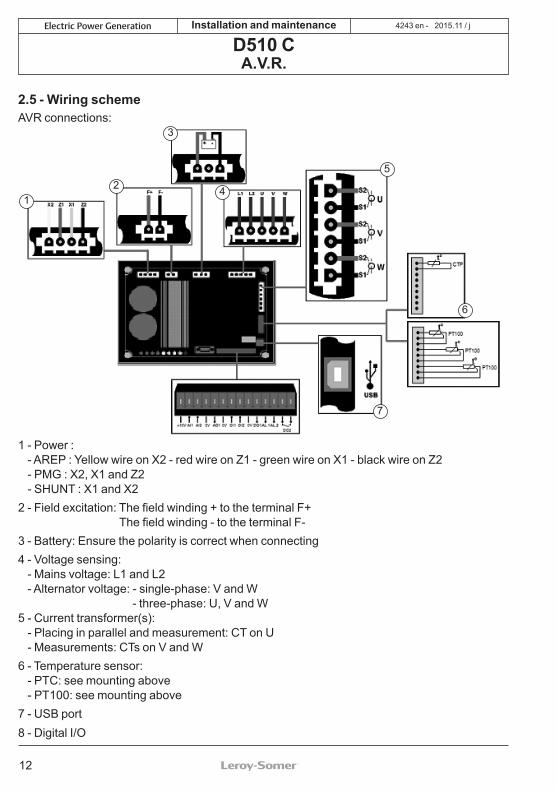
2.5 - Wiring schemeAVR connections:
1 - Power :- AREP : Yellow wire on X2 - red wire on Z1 - green wire on X1 - black wire on Z2- PMG : X2, X1 and Z2- SHUNT : X1 and X2
2 - Field excitation: The field winding + to the terminal F+The field winding - to the terminal F-
3 - Battery: Ensure the polarity is correct when connecting4 - Voltage sensing:
- Mains voltage: L1 and L2- Alternator voltage: - single-phase: V and W
- three-phase: U, V and W5 - Current transformer(s):
- Placing in parallel and measurement: CT on U- Measurements: CTs on V and W
6 - Temperature sensor:- PTC: see mounting above- PT100: see mounting above
7 - USB port8 - Digital I/O
13
2015.11 / jElectric Power Generation Installation and maintenance
D510 CA.V.R.
4243 en -
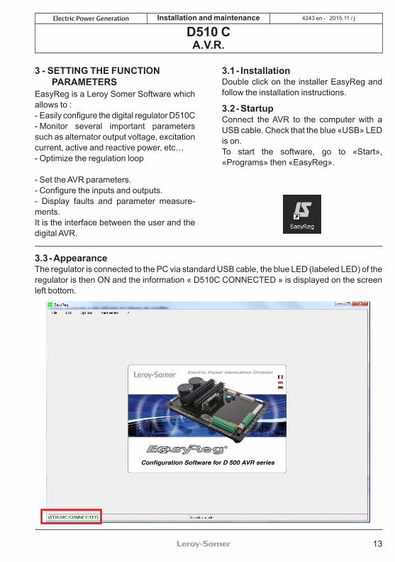
3 - SETTING THE FUNCTION PARAMETERS
EasyReg is a Leroy Somer Software which allows to :- Easily configure the digital regulator D510C- Monitor several important parameters such as alternator output voltage, excitation current, active and reactive power, etc…- Optimize the regulation loop
- Set the AVR parameters.- Configure the inputs and outputs.- Display faults and parameter measure-ments. It is the interface between the user and the digital AVR.
3.1 - Installation Double click on the installer EasyReg and follow the installation instructions.
3.2 - StartupConnect the AVR to the computer with a USB cable. Check that the blue «USB» LED is on. To start the software, go to «Start», «Programs» then «EasyReg».
3.3 - AppearanceThe regulator is connected to the PC via standard USB cable, the blue LED (labeled LED) of the regulator is then ON and the information « D510C CONNECTED » is displayed on the screen left bottom.

14
2015.11 / jElectric Power Generation Installation and maintenance
D510 CA.V.R.
4243 en -
There are four options when using this software:- New configuration- Open a configuration from a file- Open a configuration from the pre-programmed AVR.- Create customised configuration (Expert mode)
If the AVR is not connected or has never been configured, it is impossible to «Open from a D510C».PROPERTIESThe user can choose to lock the regulator to avoid the configuration modification. In that case, the configuration description and a lock code must be entered. In customised mode, only the lock code can be entered.
PRINTThe configuration can be edited in a Word or PDF format file.
3.3.1 - Languages and modes3.3.1.1 - LanguagesThree languages are available on EasyReg: French , English and German.

15
2015.11 / jElectric Power Generation Installation and maintenance
D510 CA.V.R.
4243 en -
3.3.1.2 - ModesTwo operation modes are possible:- Standard mode by default- Expert mode which offers additional functions
This mode is reserved for users who possess the skills to make certain more complex adjustments or to use the AVR in a wider range of operating conditions.
If you require the Expert mode access code, please use the main menu: click on « ? » then « About… ». The following window is displayed
Click on« Copy code » and email the PC code to: [email protected] The access code will be sent you back.
Incorrect settings can harm the AVR and the alternator and can cause serious damage (to users, loads). Select the duty type and the class according to your specification.
3.3.2 - Saving and loading the configurationSave your configuration (for the 1st time):- Go into the «File» menu and click «Save As»- Choose where you wish to save to- Name your saved configuration- Click Save As
Subsequently, to save the configuration, you just need to go into the «File» menu and click «Save».

16
2015.11 / jElectric Power Generation Installation and maintenance
D510 CA.V.R.
4243 en -
Send the configuration to the AVR:- check that the AVR is connected correctly (blue LED on) at the bottom left-hand side of the screen.- go into the «Edit» menu.- Go to : • PC --> D510C
• D510C --> PC- click « PC −> D510C ».Wait for loading to complete.
3.3.3 - New configurationThere are two possible configuration levels: standard or expert.
By default, the software is in standard mode. The AVR is programmed step by step. Access to the «Regulation Mode» page is only possible if the «Alternator Configuration» page has been filled in. The program is transferred to the D510C via the «Edit» menu then «PC => D510C» or by pressing F10 on the keypad.This software must be used in the order indicated below:1. Alternator configuration2. Regulation mode:
- Voltage regulation- Underspeed settings- Other types of regulation (PF, reactive power, manual) depending on the user’s selections.
3. Faults and digital outputs4. Monitors
3.3.3.1 - Alternator ConfigurationOpen «New configuration» from the menu bar, which takes you to the «Alternator Configuration» window. The parameters for this page are set in two parts: Alternator, Options.The wiring scheme varies according to the characteristics specified by the user.

17
2015.11 / jElectric Power Generation Installation and maintenance
D510 CA.V.R.
4243 en -
• AlternatorIn the dropdown lists or boxes, select:
1. The type of alternator
2. The length
3. The type of field excitation
4. The frequency
5. The number of stator outputs
6. The stator connections
7. The voltage sensing(single or three-phase)
Note: The information relating to items 1, 2, 3 and 4 can be found on the nameplate.
[Expert mode]: the alternators list is more expanded. In this mode it is also possible to select the Service, the temperature rise class and the alternator power.
Note: FF and G electrical connections are dedicated to single phase application, no three-phase sensing is possible.
Stator connections: Click on the question mark to get help on the stator connections.
The alternator configuration is recalled at the screen left bottom
1
2
3
4
5
6
7

18
2015.11 / jElectric Power Generation Installation and maintenance
D510 CA.V.R.
4243 en -
• Options To obtain the following options, tick the boxes:1. Temperature sensors, select either 1 PTC or 3 PT100s.2. Current transformers (CTs), select the number (1 or 3), the measurement (IN, IN/2 or IN/4) and the ratio. unless one CT is mandatory for parallel operation, PF or kVAR regulation, stator over current, unbalenced current.3. Alternator voltage transformer, enter the voltage values at the primary and at the secondary if a transformer is connected..4. Bus voltage transformer, enter the voltage values at the primary and at the secondary if a transformer is connected.5. Step-up transformer, fill the values of primary and the secondary.
The electrical schematic below shows how the «wiring scheme» part changes according to the parameters selected.
After entering the data in this page, go to the second page by clicking «Next». In some cases,you will need to adjust the workscreen in order to access the «Next» button.
1
2
3
4
5

19
2015.11 / jElectric Power Generation Installation and maintenance
D510 CA.V.R.
4243 en -
3.3.3.2 - Regulation modeAfter entering the «Alternator Configuration» part settings, fill in the «Regulation Mode» part.
4 types of regulation are offered:- Voltage- Power factor (P.F.)- Reactive power (kVAR)- Manual (I exc)
Always setting begins with voltage regulation.Caution, regulation of the reactive power PF and the quadrature droop can only be enabled if there is a CT on phase U and it has been selected.

20
2015.11 / jElectric Power Generation Installation and maintenance
D510 CA.V.R.
4243 en -
A - Voltage regulationThis page consists of two parts :
- Voltage Regulation
- Underspeed settingsSetting the parameters for this part starts with the «Voltage regulation» page and ends with the «Underspeed settings» page.
A1 - Voltage regulationThis page is split into two parts:- Settings- Options
A1.1 - Settings
1. The displayed value comes from Easyreg® database. It can be adjusted in the range ± 10% maximum.
Expert Mode: The adjustment range can be extended to ± 30%
1
2
3

21
2015.11 / jElectric Power Generation Installation and maintenance
D510 CA.V.R.
4243 en -
2. To set the voltage externally, tick the box, define by what means (POT, 0-10 V, etc) this setting will be made as well as the selected input (AI1 or AI2), then enter the desired setting range.
The setting « Digital » is used for the « +/-» mode thanks to the analogue inputs AI1 and AI2.It allows to modify the regulation reference thanks to successive pulses on AI1 and AI2.
3. If you wish to have voltage quadrature droop, tick the box and select the quadrature droop percentage.
This function is only available if a CT is used.It can be adjusted up to 10% maximum.

22
2015.11 / jElectric Power Generation Installation and maintenance
D510 CA.V.R.
4243 en -
A1.2 - Options1. If you wish to have line drop compensation, tick the box and select the type of setting by a % value or an external setting. The standard setting is 3%.This function is only available if a CT is used.
The function « Voltage line droop compensation » cannot be simultaneously activated with «reactive droop compensation».
It is possible to impose the desired compensation by direct entry of the % value or make an external adjustment (10% max 2. Select which value regulation should apply to :- mean value- true rms value To go to the next step «Underspeed settings», click «Next».

23
2015.11 / jElectric Power Generation Installation and maintenance
D510 CA.V.R.
4243 en -
A2 - Underspeed settingsThis page is split into three parts:- Starting- Underspeed- Engine
A2.1 - StartingFactory setting: disabledTo adjust Soft-start, check the box and select the duration between 0.1 s and 120 s (1 step = 0.1 s).Clicking on the question mark give help information on this function.The Soft-start reset delay (default 20s), can be adjusted from 5s to 20s.

24
2015.11 / jElectric Power Generation Installation and maintenance
D510 CA.V.R.
4243 en -
A2.2 - Underspeed
Factory setting: 48 Hz for 50 Hz58 Hz for 60 Hz1
2
1. Enter the knee-point value between 47.5 and 52.5 Hz (1 step = 0.1 Hz). An error message appears when the value displayed is outside the permitted range. The extended range is accessible in expert mode.
2. Enter the gradient value between 1.0 and 3.0 U/F (1 step = 0.1 U/F). Factory setting: 1/U/F.

25
2015.11 / jElectric Power Generation Installation and maintenance
D510 CA.V.R.
4243 en -
A2.3 - Motor help1. If the LAM function is required, tick the box and select its value between 0% and 30% (1 step = 1%).Recommended setting: LAM 9% - U/F 1.7%
1
2
2. If you wish to have a gradual increase, tick the box and select the value between 0.1 s/10 Hz and 30.0 s/Hz (1 step = 0.1 s/10 Hz).
Save (see section 3, «Save» part).
Load the configuration in the regulator :- By clicking on the button - Or by using the key F10- Or PC→D500 in « Edition » menu
Then a warning message is displayed.
Note: the recommended setting is 7 s/10 Hz

26
2015.11 / jElectric Power Generation Installation and maintenance
D510 CA.V.R.
4243 en -
B2 - SettingsIt is possible to set a fix value or use a remote adjustment in a predefined range.
1. Select the power factor value. The value depend on the alternator type.
B - Regulation of the power factor
Caution: You can only enable selection of regulation by power factor PF or selection of regulation of the reactive power KVAR, and the quadrature droop, if there is a CT on phase U which has been enabled on the alternator configuration page.
This page is split into two parts:- Digital inputs- Settings
1
2
B1 - Digital inputsCheck the digital input on which the voltage match circuit has been placed in order to enable it. The second digital input is reserved for enabling power factor regulation mode.

27
2015.11 / jElectric Power Generation Installation and maintenance
D510 CA.V.R.
4243 en -
Database Authorized area
Database not recommended area
Forbidden area
It is impossible to enter a reference value outside the limit values which are automatically set from the data on the alternator database.
Warning: When a value is outside the database recommended area, a message appears as indicated below.

28
2015.11 / jElectric Power Generation Installation and maintenance
D510 CA.V.R.
4243 en -
2. To set the power factor externally, tick the box, select the source (POT, 0-10 V, etc) for this setting and also the input (AI1 or AI2). One of the inputs may be greyed-out if it is already being used by another function.
Remote adjustment operation area
Database Authorized area
Database not recommended area
Forbidden area
Save (see section 3, «Save» section). Load the settings into the AVR by clicking the following button :

29
2015.11 / jElectric Power Generation Installation and maintenance
D510 CA.V.R.
4243 en -
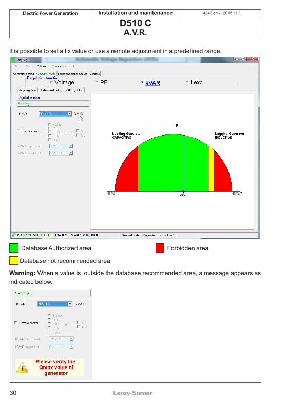
C - Regulation of the reactive power kVARCaution, regulation of the reactive power PF, and the quadrature droop can only be enabled if there is a CT on phase U and it has been configured.This page is split into two parts:- Digital inputs- Settings
C1 - Digital inputsCheck the digital input on which the voltage match circuit has been placed in order to enable it. The second digital input is reserved for enabling reactive power regulation mode.
C2 - SettingsSelect the value of the reactive power according to the load. This value depends on the alternator type.
30
2015.11 / jElectric Power Generation Installation and maintenance
D510 CA.V.R.
4243 en -
It is possible to set a fix value or use a remote adjustment in a predefined range.
Database Authorized area
Database not recommended area
Forbidden area
Warning: When a value is outside the database recommended area, a message appears as indicated below.

31
2015.11 / jElectric Power Generation Installation and maintenance
D510 CA.V.R.
4243 en -
2. To set the reactive power externally, tick the box, select the source (POT, 0-10 V, etc) for this setting and also the input (AI1 or AI2). One of the inputs may be greyed-out if it is already being used by another function.
Remote adjustment operation area
Database Authorized area
Database not recommended area
Forbidden area
Save (see section 3, «Save» part).
Load the settings into the AVR by clicking the appropriate button:

32
2015.11 / jElectric Power Generation Installation and maintenance
D510 CA.V.R.
4243 en -
D2 - External control
1. To set the excitation current externally, tick the box, select the source (POT, 0-10 V, etc) for this setting and also the input (AI1 or AI2). One of the inputs may be greyed-out if it is already being used by another function.
2. Check the digital input on which manual mode has been placed in order to activate it.
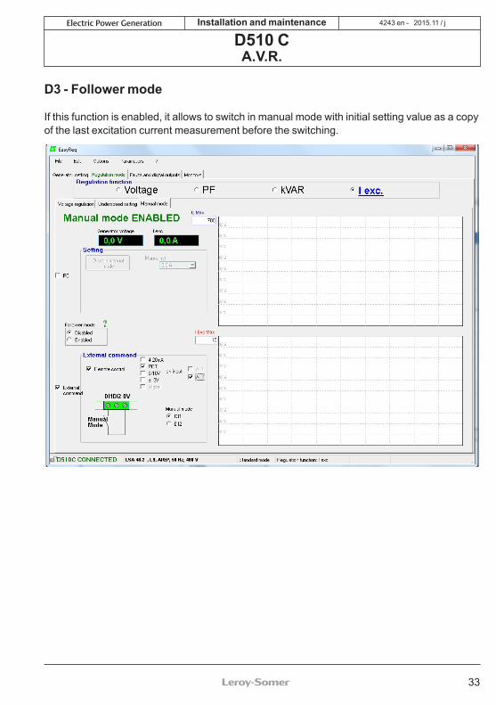
D - Manual regulation: I excThis page is split into three parts:- PC (settings)- External control- Follower mode
The manual mode can be activated and adjusted either with the PC (via EasyReg software) or remotely. In that last case, a switch allowing the activation/ deactivation of the manual mode must be connected to one of the digital inputs and the excitation current setting is achieved by the remote analogue device through the AI1 or AI2.
1
2
D1 - PCEnter the desired excitation current value between 0.0 A and 10.0 A (1 step = 0.1 A). Manual mode is enabled by clicking the corresponding button.
33
2015.11 / jElectric Power Generation Installation and maintenance
D510 CA.V.R.
4243 en -
D3 - Follower mode
If this function is enabled, it allows to switch in manual mode with initial setting value as a copyof the last excitation current measurement before the switching.

34
2015.11 / jElectric Power Generation Installation and maintenance
D510 CA.V.R.
4243 en -
3.3.3 - Faults and digital outputsThis page is split into three parts in standard mode:- Assignment of faults- Assignment of digital outputs- faults options
- Assignment of faults and digital outputsThe main faults can be supervised by assigning them to digital outputs.
NOTA : The fault « Unbalance current » is only selectable if 3 CT are checked. This page offers the possibility of assigning faults and operating modes to 4 outputs (AL1, AL2, D01 and D02).
Example of settings:- Assignment of «Overvoltage» fault to AL1- Assignment of «PT100-1 overtemperature» fault to AL2 with the maximum temperature set at 200°C- Assignment of «Loss of voltage sensing» fault to DO1- Assignment of «PF/kVAR» digital output to D02
35
2015.11 / jElectric Power Generation Installation and maintenance
D510 CA.V.R.
4243 en -
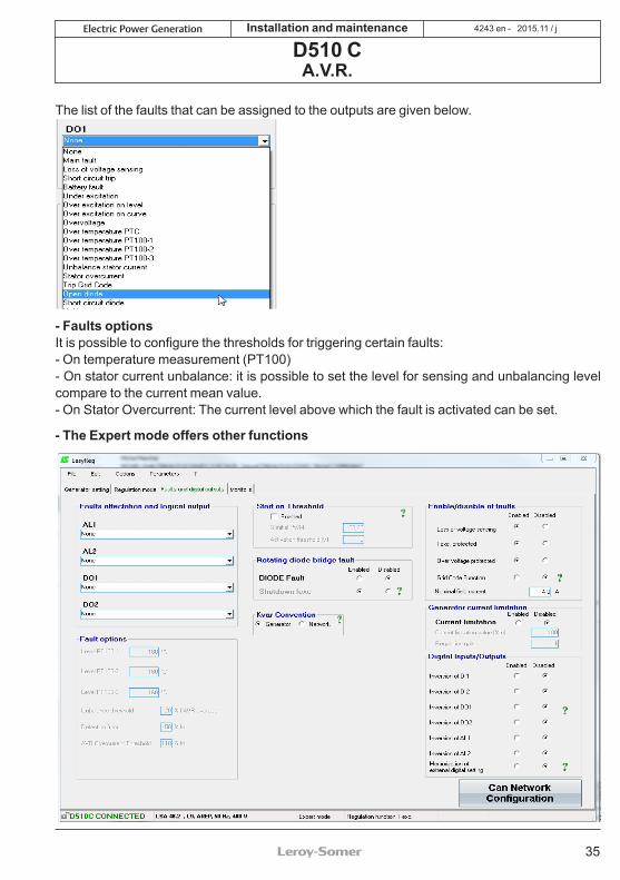
The list of the faults that can be assigned to the outputs are given below.
- Faults optionsIt is possible to configure the thresholds for triggering certain faults:- On temperature measurement (PT100)- On stator current unbalance: it is possible to set the level for sensing and unbalancing level compare to the current mean value. - On Stator Overcurrent: The current level above which the fault is activated can be set.
- The Expert mode offers other functions

36
2015.11 / jElectric Power Generation Installation and maintenance
D510 CA.V.R.
4243 en -
• [Expert mode] Start on ThresholdActivate and set this function. This function allows an initialisation of the voltage regulation in a way which avoids the voltage overshoots during voltage build up. The PMW % level reduce the excitation current up the voltage threshold voltage level. The Start on threshold can be tuned on “Faults and digital outputs” tab.NB : this function is reset 20 seconds after the engine is stopped.
• [Expert mode] Enable/disable of Faults Allows to activate/deactivate the regulator protections (overvoltage, over-excitation,..).• [Expert mode] Grid Code FunctionAllows to activate/deactivate this function. At least one CT is necessary to use this function. It allows to switch from PF regulation mode to voltage regulation mode when the voltage is out of the range -90% and 110% of the rated voltage.• [Expert mode] Nominal excitation currentThis value comes from the database but can be changed by the user. This value must be set according to the admissible excitation current for the generator.• [Expert mode] digital input/ outputsIt is possible to reverse these digital IOs.• [Expert mode] Digital external setting memorizationThis function is use in « +/-» mode; it allows to keep the regulation mode adjustment in case of DC supply cut off.
3.3.4 - [Expert mode] D510C OptionsThe regulator D510C offers several functions accessible by clicking on the button:
• [Expert mode] rotating diode bridge faultActivate/deactivate the rotating diodes state supervision of exciterIn case of the supervision of activation of this feature, the « shutdown Iexc » function must be also enabled.• [Expert mode] Generator current limitationSet this function• [Expert mode] CAN network configurationEnable CANSet the data transfer rateChoose the regulator identifierSelect the broadcast protocol (J1939 and/or Owner CAN)In the case of Owner CAN, choose the parameters to broadcast.kVAR convention: when generator convention is selected then the kVAR is considered negative when generator is consuming reactive power and vice versa.

37
2015.11 / jElectric Power Generation Installation and maintenance
D510 CA.V.R.
4243 en -
Click on OK to validate the configuration
Nota: the key F10 doesn’t allow to transfer the CAN parameters.Nota: The selection « Broadcast J1939 » locks the transfer rate at 250Kb/s
WARNING - CAN communication port (DB9) must not be connected while the D510C is energized.
38
2015.11 / jElectric Power Generation Installation and maintenance
D510 CA.V.R.
4243 en -
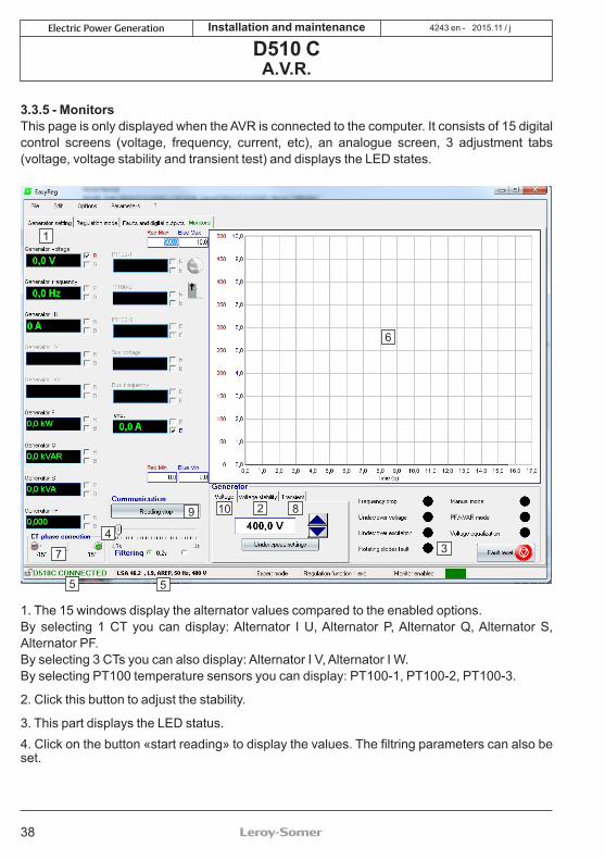
3.3.5 - MonitorsThis page is only displayed when the AVR is connected to the computer. It consists of 15 digital control screens (voltage, frequency, current, etc), an analogue screen, 3 adjustment tabs (voltage, voltage stability and transient test) and displays the LED states.
1. The 15 windows display the alternator values compared to the enabled options. By selecting 1 CT you can display: Alternator I U, Alternator P, Alternator Q, Alternator S, Alternator PF.By selecting 3 CTs you can also display: Alternator I V, Alternator I W.By selecting PT100 temperature sensors you can display: PT100-1, PT100-2, PT100-3.
2. Click this button to adjust the stability.
3. This part displays the LED status.4. Click on the button «start reading» to display the values. The filtring parameters can also be set.
1
4
2 8
6
7
9
3
5 5
10

39
2015.11 / jElectric Power Generation Installation and maintenance
D510 CA.V.R.
4243 en -
5. These 2 indications show that the AVR is connected and its characteristics have been selected.
6. 2-signal display screen. Simply tick in one of the boxes (R or B) and set the scale (Max-Min).
7. The CT phase angle should be compensated to improve the accuracy of the display by moving the «CT phase angle correction» slider.
8. Transient test: Do not start this test if in load operation.
- Click on «Transient test»,- The test voltage level setting window appears,- Enter the values, confirm, wait for the process to end.
Note: Set the minimum and maximum values within the range permitted by the generator voltage sensing device.
9. To start reading, click «Start reading». The filter value can be adjusted by 0.1 s to 3 s.
10. The voltage to track is displayed and can be adjusted thanks to the buttons . The setting of Underspeed is also directly accessible.The approach is the same for the other regulation modes (PF, kVAR et Iexc)
40
2015.11 / jElectric Power Generation Installation and maintenance
D510 CA.V.R.
4243 en -
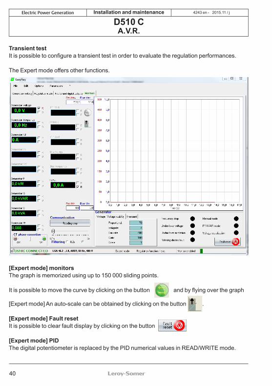
Transient testIt is possible to configure a transient test in order to evaluate the regulation performances.
The Expert mode offers other functions.
[Expert mode] monitorsThe graph is memorized using up to 150 000 sliding points.
It is possible to move the curve by clicking on the button and by flying over the graph
[Expert mode] An auto-scale can be obtained by clicking on the button .
[Expert mode] Fault resetIt is possible to clear fault display by clicking on the button
[Expert mode] PIDThe digital potentiometer is replaced by the PID numerical values in READ/WRITE mode.

41
2015.11 / jElectric Power Generation Installation and maintenance
D510 CA.V.R.
4243 en -
Warning: A wrong setting of the PID can damage the alternator.
PID setting methodology:Please use Transient Test:
1 2 3 4 5 6 Initial conditions: • Proportionnal = 10 • Integral = 1 • Derivative = 1 • Gain = 10 • Scale = 1
1 2 3 4 5 6 Adjust the proportional part to obtain a response as given in the figure below.1 2 3 4 5 6 Adjust the integral part to have the output voltage in steady states equal to desired voltage
(reference voltage).1 2 3 4 5 6 Adjust the derivative part to obtain response without oscillations.
1 2 3 4 5 6 Adjust the gain if necessary.
1 2 3 4 5 6 Change the scale value if the setting is unsuccessful and go back to step 1 2 3 4 5 6.
400V
234
42
2015.11 / jElectric Power Generation Installation and maintenance
D510 CA.V.R.
4243 en -
The table below summarises the effects which may be influenced by the PID actions.
PID controller Effect
Proportional action SpeedIntegral action Accuracy
Derivative action Stability
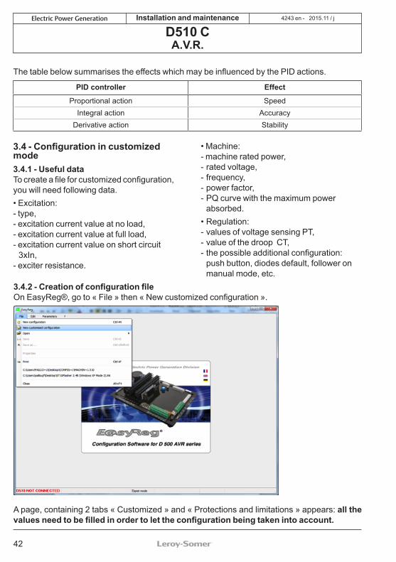
3.4 - Configuration in customized mode3.4.1 - Useful dataTo create a file for customized configuration, you will need following data.• Excitation: - type, - excitation current value at no load, - excitation current value at full load, - excitation current value on short circuit
3xIn,- exciter resistance.
• Machine:- machine rated power, - rated voltage, - frequency, - power factor,- PQ curve with the maximum power
absorbed. • Regulation:- values of voltage sensing PT, - value of the droop CT, - the possible additional configuration:
push button, diodes default, follower on manual mode, etc.
3.4.2 - Creation of configuration fileOn EasyReg®, go to « File » then « New customized configuration ».
A page, containing 2 tabs « Customized » and « Protections and limitations » appears: all the values need to be filled in order to let the configuration being taken into account.

43
2015.11 / jElectric Power Generation Installation and maintenance
D510 CA.V.R.
4243 en -
3.4.3 - Tab « Customize » 3.4.3.1 - Alternator part- Type Alternator: 20 free characters, enter the type of the machine first.
- Nominal voltage: enter the nominal voltage of the machine.- Nominal frequency: enter the nominal frequency of the machine.- Voltage sensing: check “Single phase“ or “Three phases“ box. - Apparent power: enter the nominal power of the machine.- PF Ref: enter the nominal power factor of the machine.- Field excitation system: choose the excitation type of the machine.- Nominal field excitation current: enter the nominal field current value of the machine.- Field inductor resistance: enter the exciter resistance value.
3.4.3.2 - Regulation- This part is relative to different PID used for the machine.
- Voltage for this particular case: - Proportional: 60- Integral: 3- Derivative: 1200- Gain: 80
- PF and kVAr by default:- Proportional: 10- Integral: 1- Derivative: 20- Gain: 50
- Iexc by default:- Proportional: 100- Integral: 10- Derivative: 500- Gain: 100
- Select also the negative forcing, the compensation VBus if needed.- Reselect the scale of gains PID to 1/1 or 1/50 depending on the alternator size.

44
2015.11 / jElectric Power Generation Installation and maintenance
D510 CA.V.R.
4243 en -
3.4.4 - Tab « Protections and limitations » 3.4.4.1 - General- The page appears in two parts: • the left part is relative the values to enter by the user, • the right part shows the schematics corresponding to the adjustments.- According to the limitation adjustments, a red arrow appears to allow a better understanding to what this configuration is corresponding.- In the following figure, for example, the low limit for P.F instruction.
3.4.4.2 - Limitations and protections P.F. and kVAr- Use the Capability curve of the machine. In this case, we suppose that the following diagram is:

45
2015.11 / jElectric Power Generation Installation and maintenance
D510 CA.V.R.
4243 en -
In our case we can configure the values:
- Leading PF limit (min): 0.5- Lagging PF limit 1 (max): 0.75 - Lagging PF limit 2 (max): 0.70 - Leading kVAr limit (%): -60% (we can read « -0.6 » on kVAr/kVA of the diagram PQ) - Lagging kVAr limit 1 (%): for power factor 0.75 : nearly « 0.62 »,either 62%- Lagging kVAr limit 2 (%): for power factor 0.70 : nearly « 0.65 », either 65%- Over voltage level: 110%- Delay: 10s
3.4.4.3 - Under-excitation Limitation- This limitation is more sensible. - Iexc run limitation (A): it corresponds to the minimum value from which the limitation will enter in action. - Iexc reset limitation (A): value from which the limitation is not active anymore. - Under-excitation delay (s): it must be very short such as 2s.
3.4.4.4 - Over-excitation Limitation- Iexc run limitation (A): this corresponds to the highest value of the field current when ceiling in short-circuit. - Iexc reset limitation (A): this corresponds the lowest value of the field current when ceiling in short-circuit. - Iexc shutdown (A): is the shutdown current. - Iexc short-circuit (A): excitation current value to reach the short-circuit. - Short-circuit delay (s): adjusted à 10s.
Click on the “Next >>” button The customized part of the configuration is done and the remaining settings are the same as described in the sections above.

46
2015.11 / jElectric Power Generation Installation and maintenance
D510 CA.V.R.
4243 en -
4 - CONNECTION DIAGRAMS
Digital AVR D510 CTerminal block with fuses
Warning: the secondary of the CT must not be connected to the ground.
MAIN FIELDAuxiliarywindings
EXCITER
Armature
Exciter field
white or red (LSA 50.2)
D510C
R 791
STATOR
open E 01
FUSES:F1, F2 : Ref. Mersen : E084414P - MI6SA25V10/50 or equivalent250VAC/10AF3 : Ref. Mersen : A217028Q - GDL1 or equivalent250VAC/1A
Leaflet n° 4243
Temp. sensors
CONTACTS NOT SUPPLIED BY LS
PT100or CTP
Supply:11V to30V DC
MAINSif 3F used
CT
Leds
Varis
tor
Gre
enYe
llow
Red
Bla
ck
inpu
ts/o
utpu
ts
D 510C
blue or black (LSA 50.2)
black
// CT
white
blue
DESENERGIZING
OPTIONAL
NOTE:6 leads alternator - marking T1 to T6TI 04 --> T4
Auxiliary windings
TI04 on phase U is required for droop compensation,
PF and KVAR functions
Rotating rectifiers

47
2015.11 / jElectric Power Generation Installation and maintenance
D510 CA.V.R.
4243 en -
≤ 7%
≥ 7%
Fault
Fault
Yes
Absence of voltage
Check the power supply is present on the AVR
Green "POWER ON" LED active
Check the regulation mode
Check the wiring and the supply voltage between
12 and 30 Volts
Check whether the measured voltage 7% of UN
Yes No
Check the polarity of the exciter field
Modify the wiring, then reboot the
machine if necessary
Check the exciter field connections
Modify the exciter field wiring or replace it if faulty
Check the diode bridge Replace the diode bridge if faulty
OK
Fault
Replace the AVR
Generator and control running
Start voltage regulation
No
5 - FAULT FLOW CHARTS
48
2015.11 / jElectric Power Generation Installation and maintenance
D510 CA.V.R.
4243 en -
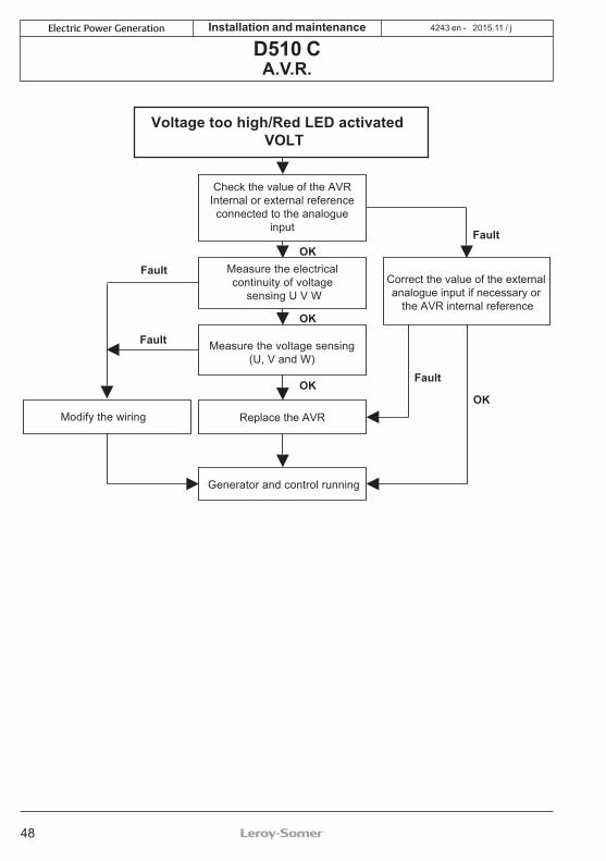
OKFault
OKOK
Fault
OK
Fault
Fault
Voltage too high/Red LED activatedVOLT
Check the value of the AVR Internal or external reference connected to the analogue
input
Measure the voltage sensing (U, V and W)
Correct the value of the external analogue input if necessary or
the AVR internal reference
Replace the AVR
Generator and control running
Measure the electrical continuity of voltage
sensing U V W
Modify the wiring

49
2015.11 / jElectric Power Generation Installation and maintenance
D510 CA.V.R.
4243 en -
OK
Fault
OKOK
OKFault
≥ 7%≤ 7%
Fault
OK
Fault
Fault
Voltage too low/Red LED on VOLT
Check the speed of rotation
Adjust the generator speed
of rotation
Check and if necessaryadjust the position of theU/F activation knee-point
Monitor the load applied to the alternator
Check the exciter field
Replace theexciter field Check whether the remanent
voltage is ≤ 7% of UN
Replace the AVR
Generator and control running
Replace therotating diodes
Readjust the load

50
2015.11 / jElectric Power Generation Installation and maintenance
D510 CA.V.R.
4243 en -
FaultOK
FaultOK
Unstable
Stable
OK
OK
Fault
Fault
OK
Incorrect regulation or Voltage unstable
Check the stability of the speed
Correct the stability of thedrive system speed
Check the D500
configuration (type of alternator and PID)
Modify the D500configuration
Adjust the PID
Check whether the load is balanced
Stabilise the load
Check the exciter field
Check the rotating diodes
Replace the D510C AVR
Replace the exciter field
Replace the rotating diodes
Generator and control running
Unstable

51
2015.11 / jElectric Power Generation Installation and maintenance
D510 CA.V.R.
4243 en -
Fault
Fault
Fault
OK
OK OK
Response time too long
Does the speed regulatorrespond quickly enough?
Adjust the AVR stabilitypotentiometer in Easyreg
Reduce the value of thegradual voltage return
(7 s/10 Hz factory setting)
Adjust the speed stability of the prime mover
Adjust the PID parametersof the controllerin Expert mode
Start generator andcontrol running

52
2015.11 / jElectric Power Generation Installation and maintenance
D510 CA.V.R.
4243 en -
OK
OK
OK
OK Fault
OK
Fault
Fault
Fault
Fault
OK
Considerable drop in voltage, on-load
Check the generatorload level
Check the quadrature droop parameter settings
Check the wiring of thevoltage reference U/V/W
Check the position andlocation of the CT on
phase U
Decrease the load
Check the value of the CT and the ratio setting
Modify PID parametersof the D510C
Start generator andcontrol running
Adjust the quadrature droop
(factory setting 3%)
Modify the wiring
Modify the wiring
Check the D500configuration
(LAM, U/F, etc)
53
2015.11 / jElectric Power Generation Installation and maintenance
D510 CA.V.R.
4243 en -
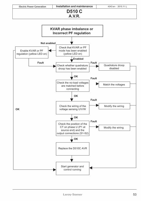
Fault
Fault
Fault
Not enabled
Fault
Fault
Enabled
OK
OK
OK
OK
OK
KVAR phase imbalance orIncorrect PF regulation
Check that KVAR or PFmode has been enabled
(yellow LED on)
Check whether quadraturedroop has been enabled
Check the no-load voltagesare matched before
connecting
Quadrature droopdisabled
Enable KVAR or PFregulation (yellow LED on)
Check the wiring of thevoltage sensing U/V/W
Match the voltages
Check the position of theCT on phase U (P1 atsource end) and the
output connections (S1-S2)
Replace the D510C AVR
Start generator andcontrol running
Modify the wiring
Modify the wiring

54
2015.11 / jElectric Power Generation Installation and maintenance
D510 CA.V.R.
4243 en -
OK
OK
OK
OK
OK
Fault
Fault
Fault
Fault
PF or KVAR range incorrect
Replace the AVR
Check the selection mode (internal or external)
Check that KVAR or PFmode has been enabled
Start generator andcontrol running
Enable KVAR or PFregulation (yellow LED on)
Enable the setting mode
Check and modification ofthe setting range and limits
55
2015.11 / jElectric Power Generation Installation and maintenance
D510 CA.V.R.
4243 en -
OK
OK
OK
OK
OK
FaultFault
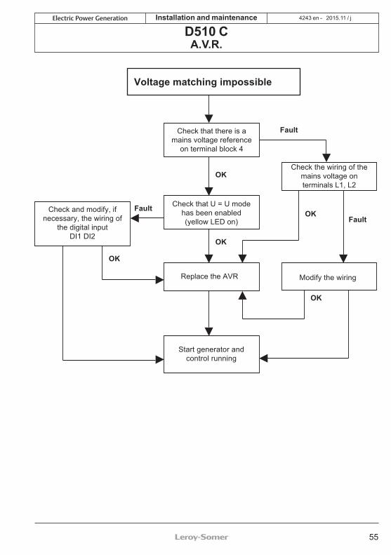
Fault
Voltage matching impossible
Check that there is amains voltage reference
on terminal block 4
Check that U = U modehas been enabled(yellow LED on)
Replace the AVR
Check and modify, ifnecessary, the wiring of
the digital inputDI1 DI2
Start generator andcontrol running
Modify the wiring
Check the wiring of themains voltage onterminals L1, L2
56
2015.11 / jElectric Power Generation Installation and maintenance
D510 CA.V.R.
4243 en -
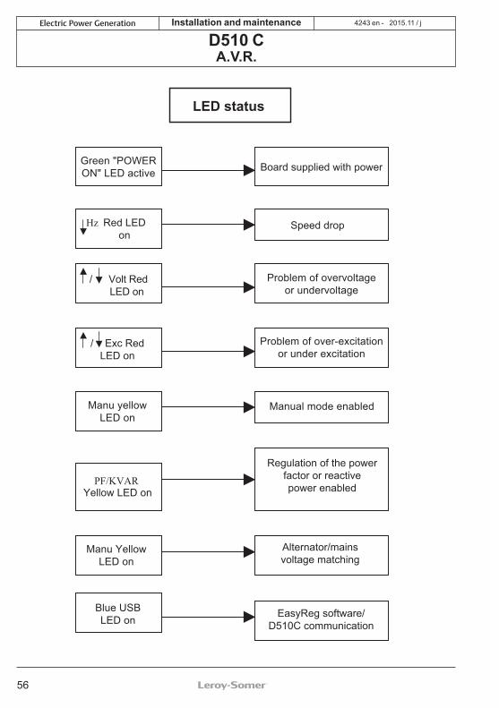
LED status
Speed drop
Board supplied with powerGreen "POWERON" LED active
Problem of overvoltageor undervoltage
Hz Red LEDon
/ Volt RedLED on
/ Exc RedLED on
Problem of over-excitationor under excitation
Manu yellowLED on
PF/KVARYellow LED on
Blue USBLED on
Manu YellowLED on
Manual mode enabled
Regulation of the powerfactor or reactivepower enabled
Alternator/mainsvoltage matching
EasyReg software/D510C communication

57
2015.11 / jElectric Power Generation Installation and maintenance
D510 CA.V.R.
4243 en -

58
2015.11 / jElectric Power Generation Installation and maintenance
D510 CA.V.R.
4243 en -

59
2015.11 / jElectric Power Generation Installation and maintenance
D510 CA.V.R.
4243 en -

www.emersonindustrial.comwww.emerson.com/epg
- 2015.11 / j4243 en