lesson 1 : software characteristics ,components and
TRANSCRIPT

Self Learning Material
Software Engineering(PDCA-203)
Course: Post Graduate Diploma inComputer Applications
Semester-II
Distance Education Programme
I.K. Gujral Punjab Technical University
Jalandhar

Syllabus
I.K. Gujral Punjab Technical University
PDCA-203 Software EngineeringSECTION-A
Software: Characteristics, Components, Applications, And Software Process Models: Waterfall,Spiral, Prototyping, Fourth Generation Techniques, Concepts of Project Management, Role ofMetrics &Measurements.
SECTION-B
S/W Project Planning: Objectives, Decomposition techniques: S/W Sizing, Problem-basedestimation, Process based estimation, Cost Estimation Models: COCOMO Model, The S/WEquation, System Analysis: Principles of Structured Analysis, Requirement analysis, DFD, EntityRelationship diagram, Data dictionary.
SECTION-C
S/W Design: Objectives, Principles, Concepts, Design methodologies: Data design, ArchitecturalDesign, procedural design, Object -oriented concepts
SECTION-D
Testing fundamentals: Objectives, principles, testability, Test cases: White box & Black boxtesting, Testing strategies: verification & validation, unit test, integration testing, validationtesting, system testing.
Suggested Readings/ Books:
1. Roger. S. Pressman, Software Engineering - A Practitioner's Approach, 7th Edition, McGraw Hill,2010.
2. Rajib Mall, “Fundamental of Software Engineering “, 3rd edition, PHI, 2009.
3. Naseeb Singh Gill, “Software Engineering: Software reliability, testing and quality, KhannaBookPublishing, 2011.

Table of Contents
Chapter No. Title Written By Page No.
1 Software concepts Ms. Navneet Bawa,AP, ACET Amritsar
1
2Software Process models
Mr. Gagan Kumar,AP, DAVIET,Jalandhar
17
3Software Project Management
Ms. Pavitar Singh, AP,ACET Amritsar
31
4Software Measurement and Metrics
Mr. Rajbir Singh, AP,ACET Amritsar
54
5Software project planning
Mr. Rupesh Gupta,AP, ACET Amritsar
72
6Cost estimation models
Kanwaljit Singh, AP,ACET Amritsar
92
7
System Analysis
Mr. Gagan Kumar,AP, DAVIET,Jalandhar
107
8
Software Design
Mr. Gagan Kumar,AP, DAVIET,Jalandhar
122
9
Software design methodologies
Mr. Gagan Kumar,AP, DAVIET,Jalandhar
136
10
Object oriented concepts
Mr. Gagan Kumar,AP, DAVIET,Jalandhar
151
11
Software Testing Techniques
Mr. Gagan Kumar,AP, DAVIET,Jalandhar
165
12Verification and Validation
Mr. Rupesh Gupta,AP, ACET, Amritsar
179
Reviewed ByVishal Sharma
DAV College, Jalandhar
© IK Gujral Punjab Technical University Jalandhar
All rights reserved with IK Gujral Punjab Technical University Jalandhar

1
Lesson 1: Software Characteristics, Components and Applications
1.0 Objectives
1.1 Introduction
1.1.1 Software
1.1.2 Program vs. Software product
1.1.3 Software Engineering
1.1.4 Software Engineering:- Elements
1.1.5 Scope and necessity of software engineering
1.1.6 Software Evolution
1.2 Software Characteristics
1.2.1 Characteristics of good software
1.3 Software Components
1.4 Software Applications
1.5 Summary
1.6 Glossary
1.7 Answers to Self Assessment Questions
1.8 References/ Suggested Readings
1.9 Model Questions
1.0 Objectives
After studying Software Engineering students will be able to
Elicit Requirement and Scope of Software Design
Elicit Scope and Necessity of Software Engineering
Identify the Causes and Solutions of Crisis in software Engineering.
Identify various Components of Software Engineering
2
Identify various techniques and skills used for development of engineering tools.
1.1 Introduction
1.1.1 Software
A software is a set of step by step instructions that when executed provide desired output. In
other words software is a data structure that enables the programs to change the information
according to the requirement.
1.1.2 Program vs. Software product
Individuals are developing programs for their personal use. Programs are smaller in size and
have functionality that is limited but software products are category of larger system. While
developing a program, the programmer is the user of his program but in the case of software
product user are the ones who have not developed the software product. Program is a single
developer approach while a software product involves a large number of developers are there.
For a program, the user interface may not be very important, because the programmer is the sole
user. On the other hand, for a software product, user interface must be carefully designed and
implemented because developers of that product and users of that product are totally different.
1.1.3 Software Engineering
As a discipline, software engineering is a branch of engineering that deals with all aspects of
software production from the system specifications to implementation and maintenance of the
system years after its use. Software engineering has progressed drastically in few years,
particularly as compared to other engineering disciplines. Computing, in early years was quite
small as compared to the present situation. Notable feature is the progression of software
engineering in the past few years. It has shown its visibility in almost all the fields including
Scientific, Military application, radar and software developers to the people of all ages. “Today,
software engineering is working behind, virtually in almost all aspects of our lives, from the
critical systems that affect our lives directly and indirectly for our well-being.
1.1.4 Software Engineering: - Elements
Requirement Specifications

3
Design Specifications Testing Maintenance Configuration management Quality Assurance.
Requirement Specifications:- A software requirements specification (SRS) is a detail
description of the purpose and conditions for software under development. The SRS in detail
explains what the software is going to deliver and how the expected output will come out to
be. SRS generally reduces the time and effort that is required by developers to achieve on
time specified goals and it also reduces the cost of development. A good SRS describes the
way the applications will interact with system hardware, and programs and users of the
system under consideration in a wide variety of real-world situations. Parameters such as
operating speed, response time, availability, portability, maintainability, footprint, security
and speed of recovery from adverse events are evaluated.
Design Specifications: - A specification in the design phase consists of detail document
which contains information about various characteristics of a project to set specified criteria
that developers should meet. Whenever a structure is required design phase comes into
existence. For example, specification document of design must include all necessary
environmental factors, drawing, designs ergonomic factors, cost, maintenance that will be
required, quality, safety, documentation and description. It also tells specific examples of
how the design of the project should be executed, helping others work properly.
Testing: - Software testing is a technique that is performed to provide stakeholders with
information about the quality of the product or service under test. Testing also provides
independent and objective view to allow the business to understand the risks of implementing
software. Test techniques include, the process of executing programs or applications with the
intent of finding errors or software bugs.
Software testing, depending upon the application under consideration can be implemented at any
time in the development process. Usually, most of the testing effort occurs after the requirements
have been elicit and the coding process has been done. As such, the methodology of the testing is
taken care by the software development methodology applied.

4
Different software development models will concentrate on the test effort at different level in the
development process. Newer development methods, like Agile, often employ test driven strategy
and place an increased section of the testing in on developer side, before it reaches a formal team
of testers. In a more traditional model, most of the test execution occurs after the requirements
have been defined and the coding process has been completed.
Maintenance: - The process of changing a software system or component after delivery to
correct errors and improve performance or other characteristics, so as to adapt changing
environment.
Major issues associated with Maintenance Problems are:-
Unorganized or unstructured code
Limited knowledge in particular domain
Limited documentation
Software maintenance tools
Tools that are required to gain insight in static structure of the system
Tools to gain inside view of the system in dynamic behavior
Tools to inspect history of different version of same software.
Configuration Management:- A set of management directives within the software engineering
process so as to develop a baseline for the software under consideration. Software Configuration
Management consists of the disciplines and techniques of controlling and evaluating the
changes to software products during and after the software engineering process.
Quality Assurance:-
• Controlling Variations in the system is most important in assuring Quality.

5
• Software developers strive to control the
– Processes implied
– resources used
– end product quality characteristics
• Quality of design
– refers to characteristics designers specify for the end product to be constructed
• Quality of conformance
– degree to which design specifications are followed in manufacturing the product
• Quality control
– series of inspections, reviews, and tests used to ensure conformance of a work product to
its specifications
• Quality assurance
– auditing and reporting procedures used to provide management with data needed to make
proactive decisions
1.1.5 Scope and necessity of software engineering
Software engineering discipline that can be viewed as systematic steps for development of
software based on some past experiences .The experience is arranged in the form of guidelines
that are used to develop particular software. For writing small programs you need not to be
familiar with software engineering principles. But while developing programs of larger size,
one must know the principles of software engineering for developing good quality software.
Software has evolved across time.In early 1950, largely the programs usually were being
written in low level language. Programs consisted of a few thousand of lines of code, i.e. quiet
small in size. Individual style of programming was used at that time based on some prior rule of
thumb or intuitions or heuristic techniques. Exploring such type of programming is called
exploratory style. However, the size and complexity of programs have grown over a period of
years, which underlines the scope and necessity of software engineering
Self assessment questions/Exercise – I
1. Define Software.
2. How is a program different from Software Product?

6
3. List various elements of Software engineering.
1.2 Software Characteristics
While developing software, the developer must understand the characteristics of the software. It
is usually required to make it different from other software. While constructing any hardware
(analysis, design, testing) its prototype is converted into physical form. For eg:- Construction of
Computer system , involves steps form initial design drawings to integration of chips and other
parts etc.
Software is basically a logical concept rather than physical concept. Therefore, Software has
characteristics that are very much different from hardware.
1. Software is not manufactured it is Engineered or Developed: Though, there may -exist
similarities between software development and manufacturing of hardware. Both the
activities are performed differently. Both the activities are performed by people and in both
activities quality is the major concern, but the approach for developing them is
considerably different.
2. The considerable difference is wearing out. Software never wears out while the hardware
does wear out. This can be represented by a curve Called Bathtub in which , it indicates
that during early years the failure rate is high, defects are corrected and failure rate drops to
some steady state level. With the passage of time, failure rate increases with time as
components suffers from various envoirmental and physical factors.

7
Infantmortality Wear-out
Fig 1.1
3. Although industry is showing a drift towards component based development of software,most software are custom built.
1.2.1 Characteristics of good software
The software must deliver the accurate and timely results that can only be achieved by
functionality and performance, and software should be one that is easy to maintain,
dependable, efficient and acceptable.
1. Maintainability: - This is the major Characteristics of good software, software should be
able to evolve itself with changing need of user.
2. Dependability: - Dependability of software means that software is reliable or trustworthy.
3. Efficiency: - Efficient utilization of various components should be more for good software.
4. Acceptability: - Acceptability of the software by the user end is also a feature of good
quality software.
1.3 Software Components

8
Software component is usually a software package or a web service, a web resource, or
a module. A Module encapsulates a set of related data or functions.
Components contain different system processes. Data and functions are encapsulated inside
each component in such a way that they are semantically related. As far system related co-
ordination is concerned, components usually communicate with each other via various
interfaces. When a component provides services to other parts of the system, it adopts
a given interface that specifically includes the services that other components can use. This
interface is necessary for the component –in the client server environment- the client does
need not to know about the inner details of the component and its implementation in order to
use those components.
1.4 Software Applications
Software is applied in situations where some predefined set of procedural steps like an algorithm, has
been defined. Type of content and determinacy are important factors in figuring the nature of a software
application. By content we mean form of incoming and outgoing information. For example, many
business applications use highly structured input data (a database) and produce reports that are well
structured.
Determinacy refers to the predicting sequence and timely information. An engineering program accepts
data that have a predefined set of sequence, executes the analysis algorithm(s) without interrupting, and
produces output data in report format. Such applications are determinate type of data.
The following are some the major software types :-
System software: Service programs or system software are written to service other programs.
Compilers, editors, and file management utilities programs are some commonly used system software,
that structures the data that are complex and determinate while Other systems applications such as
operating system elements and components, device drivers, processors that process indeterminate data.
In all cases, the system software area is characterized by largely interaction with computer hardware;
multiple users effective usage; concurrent operations that requires process scheduling, sharing various
resources, and managing processes; complex data structures.
9
Real-time software: Software that usually controls the real-world events as they occur in real time is
called real time. Real time software include information gathering component that gathers and formats
the necessary information from external sources, an analysis component that transforms information as
required by the application program, a control/output component that responds to the external
environment, and a monitoring component that coordinates the other components so that real-time
response (typically ranging from 1 millisecond to 1 second) can be achieved.
Business software: Information systems that are used in business applications comes under this
category, in this processes has much larger domain as compared to other software. Payroll systems,
inventory system, account receivable system also called discrete system has evolved into management
information system (MIS) software that accesses one or more large databases also known as BIS
(business information system). Applications area includes reformulation of present data in such a way
that facilitates operations and decision making of Business system. Apart form traditional data
processing application, business processing software applications also includes computing techniques
that are much more interactive than earlier systems. Points-of- sale, transaction processing systems are
some of the examples of business information systems.
Scientific software: Such Software range from automotive to astronomy and orbital dynamics to
molecular biology. Somehow largely modern applications within the scientific area show a distance
from traditional numerical algorithms approach. Interactive applications that include Computer-aided
design, simulations, and applications have taken real-time system software characteristics.
Embedded software: Intelligent software, also known as embedded software have taken a larger space
in industrial consumer market . Embedded and intelligent software are used to control varied products.
Embedded software performs very limited functionality. Functionality includes controlling various
activities or events like keypad controlling in microwave oven etc. Significant capabilities include fuel
control in an automobile, dashboard displays, and braking systems).
Personal computer: Exponential rise has been seen in personal computer software market. Over the
past two decades, Word processing, computer graphics, multimedia applications, spreadsheets,
entertainment software, personal and business financial applications, external network, and database
access are only a few of hundreds of applications.
Web-based software: Web Base software basically runs on server while user connect s it from their
computers, They are also used to develop and use web applications, HTML, DHTML,XML, PHP are
some of the examples of web based software.

10
Artificial Intelligence software: Artificial intelligence (AI) software makes use of inference
mechanism to solve complex problems that hardly require computations and are based on
straightforward analysis. Expert systems, also called knowledge based systems, pattern recognition
theorem proving, and game playing, neural network comes under this category.
1.4.1 Application Areas
1. Research& Development:-In Research & Development, software aids in projecting future
developments and by simulating software they can predict the behaviour of various known events or
nondeterministic aspects of the research.
2. Marketing and Sales:- In the field of Marketing and sales , software are used to produce product
presentations , for analysis and predicting sales and cost benefit analysis can also be done through such
software.
3. Accounting: - Accounting software offer benefits such as single time data entry for sharing and
integration of various applications and generation of tax returns, creating solutions that work together to
organize and streamline tax, accounting and workflow.
4. Banking system: - Core Banking Software and its interfaces allow commercial banks to interconnect
to other modular software and with the inter-bank networks. Trading software is also part of banking
software used to access capital markets.
5. Education sector: - These Software aid in learning and organization of study material. Such software
is similar to tutor to assist with studying. Millions of subjects and can be customized for almost any
learning. With the need for institutions to become "paperless", more educational institutions are looking
for alternative ways of assessing and testing student’s performance in virtual environment. Assessment
software prompt students to complete online tests and examinations that is, usually networked. The
software then evaluates and score each test transcript and gives results for each student.
6. Military applications:-Military forces are using wide range of equipments at their disposal. Tracking
that equipment can be a challenge. For communication, and other purposes military is using software.
The example of such software is Intellitrack.
1.4.2 Software Crisis
Issues associated with developing and maintaining software are termed as a "crisis." Only few observers
have been able to figure out the impact of some of the more complex software failures that have

11
occurred over the past few years. The great successes achieved by the software industry in developing
complex applications have led many to question whether the term software crisis is accurate or not. It is
true that software people succeed more often than they fail. What we really have may be something
rather different.
1.4.3 Causes and solutions for software crisis.
To understand the software crisis in simple words, we can say that the expenses that organizations all
around the world are incurring on software purchases compared to those on hardware purchases have
been showing a shocking trend over the past few years.
Organizations are spending more and more portion of their budget on software development. Not only
are the software products more expensive than hardware, but they also present a host of other problems
to the customers: software products are difficult to change, debug, and enhance; use resources non-
optimally, fail to meet the user requirements, are far from being reliable and often crash, and are usually
delivered late. Among these, the trend of increasing software costs is probably the most important factor
of the present software crisis. Some Causes of Software Failure are larger & complex problems,
inadequate training in software engineering, increasing skill shortage in specific field, and low
productivity improvements.
Self assessment questions/Exercise – II
True or False
1. Software are manufactured as it yields product.2. Process is another name of software.3. Over budgeting may be one of the causes of software failure that leads to Software Crisis.4. Adequate Training is must for timely delivery of Software.5. Complex software size leads to software Crisis.
Fill in the Blanks
1. Problems associated with software development are called Software ________.2. __________ software use inference mechanism to solve Complex Problems.3. Real-time software includes gathering information in __________4. Software design is _________of Software Engineering.5. Tax Returns are handled by __________Software.

12
Multiple Choice Questions
1. Which is the main cause of software crisis?
a) Over Intelligent developers.b) Lack or resources.c) Shortage of skilled manpowerd) Lack of progress of software engineering.
2. Software product efficiency does not include ________
a) responseb) licensingc) memory usaged) processing time
3. The reason for software bugs and failures is due to
a) software companiesb) developersc) Both a and b
4. What is the final Outcome Of requirement analysis and specification phase?
a) drawing DFDb) SRS Documentc) coding the projectd) the user Manual
5. The individual or organization who wants a product to be developed is known as the:
a) Developer
b) User
c) Contractor
d) Initiator
e) Client.
6. The nature of software applications can be characterized by their informationa) complexityb) contentc) determinacyd) none of the above

13
7. …………………. software resides only in read only memory and is used to control products andsystems for the consumer and industrial markets.
a) Business
b) Embedded
c) System
d) Personal
8. . …………….. is a sub discipline of computer Science that attempts to apply engineering
principles to the creation, operation, modification and maintenance of the software components
of various systems.
a) Computer Engineering
b) Hardware Engineering
c) Software Engineering
d) Component Engineering
9. Which one of the following is not a software process quality?
a) Productivityb) Portabilityc) Timelinessd) Visibility
1.5 Summary
Software is a set of instructions used to produce desired output. Software is not manufactured; rather it is
engineered or developed. An element of software engineering usually involves various phases from
requirement analysis to maintenance. Some of the major characteristics of good software are its
maintainability, dependability, Efficiency and acceptability. Components of software include data and
programs. Some types of software are system software, real-time software, artificial Intelligence
software, embedded software. Application areas of software engineering are education sector, military,
accounting system, research and development etc.

14
1.6 Glossary
Software: It is a set of step by step instructions that when executed provide desired output.
SRS: A software requirements specification (SRS) is a detail description of the purpose and conditionsfor software under development.
Software component: It usually a software package or a web service, a web resource, or a module.
Module: It encapsulates a set of related data or functions.
1.7 Answers to Self Assessment questions /Exercise- I
Ans 1: Software is a set of step by step instruction that when executed provide desired output. Inother words software is a data structure that enables the programs to change the informationaccording to the requirement.
Ans 2: Programs are smaller in size and have functionality that is limited but software products are
category of larger system. Software product, a large number of developers are there.
Ans 3:
Requirement Specifications Design Specifications Testing Maintenance Configuration management Quality Assurance.
Answers to Self Assessment questions /Exercise- II
True or False
1. F2. F3. T4. T5. T
Fill in the Blanks

15
1. CRISIS2. ARTIFICIAL3. REAL TIME4. PHASE5. ACCOUNTING
Multiple Choice Questions
1. c2. b3. b4. d5. e6. c7. b8. a9. a
1.8 References/Suggested Readings:
1. Roger. S. Pressman, Software Engineering - A Practitioner's Approach, 7th Edition, McGraw Hill,2010.

16
2. Rajib Mall, “Fundamental of Software Engineering “, 3rd edition, PHI, 2009.
3. Naseeb Singh Gill, “Software Engineering: Software reliability, testing and quality,Khanna Book Publishing, 2011
1.9 Model Questions
1. Explain how Software Engineering is an Engineering Discipline.
2. What are characteristics of good software design?
3. Discuss exploratory style of Programming.
4. Explain Bath tub curve in detail.
5. Elaborate the phases of Software Engineering.

17
Lesson- 2 Software Process models
Structure of the lesson
2.0 Objective
2.1 Introduction
2.2 Software process
2.3 Life cycle model
2.4 Different software life cycle models
2.4.1 Classical waterfall model
2.4.2 Prototype Model
2.4.3 Spiral model
2.5 Agile development model
2.5.1 Scrum Methodology
2.5.2 Extreme Programming or XP
2.6 Summary
2.7 Glossary
2.8 Answers to check your progress/self assessment questions
2.9 References/ Suggested Readings
2.10 Model questions
2.0 Objective
After studying this lesson, students will be able to:
1. Define the concept of software process.
2. Discuss various software life cycle models.
3. Explain different phases of a life cycle model.
4. Describe the need of agile methodology.
5. Explain XP and Scrum methodologies of Agile Development.
2.1 Introduction
IT industry did go through a face that is popularly known as software crisis. Major
software projects either failed or did not finish. Cost of managing large software's went
out of bound. It all happened because there were no software development models

18
available at that time. Major thrust was on reducing the cost and improving the efficiency
of computer hardware. Soon the experts realized that there was an emergent need of
software engineering too, and need to develop some models to manage the progress of
software projects.
2.2 Software process
A software process is broader term than the software methodology. It includes all the
activities performed in the software development phases and also the methodology used
to carry out each activity.
2.3 Life cycle model
A software process model is also known as software development life cycle SDLC. It is a
descriptive representation of the software life cycle. A life cycle model represents all the
necessary activities needed to make a software product transit through its life cycle
phases. It also specifies the strict order in which these activities should be preformed.
Different life cycle models map the activities to phases in different
ways. No matter which life cycle model you decide to use, all the basic activities are
performed in it, only the ordering may change. Single life cycle phase may include more
than single activity. For example, activities like structured analysis and structured design
may be included in the single phase called design.
The need for a software life cycle model
It is must that a software development team follows a software life cycle model; selection
of the model may depend on the team. Software development process using life cycle
model is more systematic and disciplined. Members of the team must be clear of what
activities need to be performed and what time. Absence of this understanding could lead
to chaos. For example, consider that if different teams are assigned development work
for different phases and the coding team starts with coding even before the design team
finishes with the design, could lead to the failure of the project.
A software life cycle model defines entry and exit criteria for each phase and each phase
can start with their activities only after their entry criteria is satisfied. Consider the last
example, the coding phase should be allowed to start only after the design process is

19
over. Absence of software development life cycle also make is difficult to monitor the
progress of the software development.
Check your progress/ Self assessment questions- 1
Q1. Define software process.
________________________________________________________________________
________________________________________________________________________
________________________________________________________________________
Q2 A software process model is a _____________ representation of the software life
cycle.
Q3. Single life cycle phase may include more than single ___________________ .
Q4. A software life cycle model defines _______ and __________ criteria for each phase
2.4 Different software life cycle models
Some of the commonly used life cycle models are as follows:
2.4.1 Classical waterfall model
It is the easiest software life cycle model to follow. Easy or elegant it may be, it is not the
most practical model used in actual software development projects. It is more of a
theoretical model used to explain the various phases of the software life cycle and it acts
as the base for deriving all other life cycle models. Study of waterfall life cycle model
forms the essential part, even if you want to follow some other mode:

20
Figure 2.1 Waterfall Model
[source: Source: Fundamentals of software Engineering by Rajib Mall, PHI.]
It is called a waterfall model, because the process flow from one phase to the next
phase is like water falling downwards, which means you cannot move backwards or
upwards.
Common phases of waterfall life cycle model"
1. Feasibility Study
2. Requirements Analysis and Specification
3. Design
4. Coding and Unit Testing
5. Integration and System Testing
6. Maintenance
Feasibility study: -
Feasibility study is carried out to ascertain if it is feasible or viable to develop the
software from technical, economic, social and other key factors. The process starts with
the project leaders visiting the client side to get a sense of client requirements. They study
different input data, constraints on the behaviour of the system, kind of processing
needed, and output data to be produced by the system. Once they are familiar with the
problem in hand, they try to formulate different solutions for the problem in hand. Then

21
they try to estimates the cost of each solution in terms of time needed, investment
involved, work force needed and much more. Next obvious thing is to understand the
budget of the customer and offer the solution that is feasible in that budget.
Requirements analysis and specification phase: -
Objective of this phase is to understand and document all requirements of the customer.
Activities in this phase consists of activities like requirements gathering and analysis, and
requirements specification.
Requirements gathering activity involves collection of all information from the customer
regarding the product to have clear understanding of the customer requirements. It helps
to remove the incompleteness and inconsistencies. The requirements analysis activity is
performed to collect relevant data related to the product, by the means of interviews and
discussions from the users of the
product. Information or data collected from the users may not be complete, or may
contain several contradictions and ambiguities, since each user typically has only a
partial view of the system.
Hence, further round of discussions with the customer are needed to overcome these
contradictions and ambiguities. Once you are done with it, requirements specification
activity is conducted to systematically organize the user requirements into a Software
Requirements Specification (SRS) document. This document consists of both the
functional and non-functional requirements, as well as the goals of implementation.
Design phase: -
The goal of the design phase is to design a structure that is suitable for implementation in
some programming language. This structure is derived from the SRS document. The
design phase can be carried out using either of the two design approaches:
a. Traditional design approach
In case of traditional design approach; initially a structured analysis of the requirements
specification is carried out where the detailed structure of the problem is examined,
followed by structured design activity in which the results of structured analysis are
transformed into the software design.

22
b. Object-oriented design approach
In case of object-oriented design approach, objects in the problem domain and the
solution domain are first identified. The object structure is then obtained by identifying
the relationships between various objects and creating the detailed design.
Coding and unit testing phase: -
It is also called the implementation phase. In this phase you translate the design structure
into source code using any programming language. Each component of the design is
implemented as a program module. These modules are then tested individually and in
isolation of each other. It is also called unit testing.
Integration and system testing phase: -
Unit testing is followed by integration of different modules. The modules are integrated
in a planned manner. Integration is done step by step, i.e. integrating 2 modules at one
step and incrementally merging these integrated modules. System testing is carried after
all the modules have been successfully integrated and tested. It is performed to check if
the software as a whole meets all the requirements laid down in SRS document.
System testing includes following testing activities:
α– testing: It is the system testing performed by the development team.
β– testing: It is the system testing performed by a friendly set of customers.
Acceptance testing: It refers to the system testing performed after the product delivery, by
the
customer itself.
System testing is carried out according to the system test plan document. The system test
plan specifies testing related activities, schedule of testing, allocated resources , test cases
and the expected outputs for each test case.
Maintenance phase: -
Maintenance may require more effort that the actual implementation phase. Maintenance
phase consist of the following activities:
a. Corrective maintenance: Correcting of errors that could not be discovered during the
implementation phase.

23
b. Perfective maintenance: Improving or enhancing the system implementation as per the
customer’s requirements.
c. Adaptive maintenance: Getting the software to work on a new
computer platform or with a new operating system.
Check your progress/ Self assessment questions- 2
Q5. What is an SRS?
________________________________________________________________________
________________________________________________________________________
________________________________________________________________________
Q6 Explain the traditional approach for design phase.
________________________________________________________________________
________________________________________________________________________
________________________________________________________________________
Q7. _________________ testing is carried after all the modules have been successfully
integrated and tested.
Q8. Correcting of errors that could not be discovered during the implementation phase is
called _________________ maintenance.
Disadvantage of classical waterfall model
The biggest drawback of classical waterfall model is that, it assumes that the engineers do
not commit any mistake during all phases. Unfortunately, it is next to impossible.
Waterfall model does not provide the scope to return back to earlier phases ,in case errors
are detected and you have to start afresh from phase 1. It is not possible to strictly follow
the classical waterfall model for software development process.
A variation of classical waterfall model called iterative waterfall model became very
popular. In case iterative waterfall model, there was a provision of moving back to any
phase in case a correction was encountered.

24
2.4.2 Prototype Model
A prototype is a toy or pilot implementation of the system. Rather than developing the
complete project, A prototype exhibits only the limited functional capabilities as
compared to the actual software. A prototype is built using several shortcuts. A prototype
turns out to be a very crude version of the actual system.
A prototype is extremely useful in illustrating the formats of input data, messages,
reports, etc. to the customer. It helps in getting a better insight of the customer
requirements. A prototype for example is able to exhibit as to how screens might look
like, how the user interface would behave, etc. it is quite similar to a real estate
architecture of a building, where the customer is able to get a feel of how the final project
will look like, and even suggest changes
Also, it is highly improbable to get everything right in the very first version, so, it is
better to design a prototype instead of full project, so that it is easy to incorporate the
changes.
Sometimes the technical issues related to the SRS are not clear and the prototype is able
to address all such issues. Also sometimes the customer itself is not able to express its
requirements.
2.4.3 Spiral model
Figure 2.2 Spiral Model
Source: Fundamentals of software Engineering by Rajib Mall, PHI.

25
The diagrammatic representation of spiral model is like a spiral with multiple iterations.
The number of iterations in it are not fixed. A single iteration of spiral represents a single
phase of the software process. The innermost iteration is concerned with the first phase
called the feasibility study, the next iteration with requirements specification, and so on.
Also, each phase in spiral model is split into four sectors as shown in the figure above.
Activities carried out in each sector of a single phase in spiral model are as follows:
1. Objectives of the phase are identified in the first sector.
2. In the second sector, a detailed analysis is carried out for each identified project risk
and steps are taken to reduce the same.
3. Third sector involves the activities concerned with the development and validation of
next level of the product.
4.Fourth and the last sector is concerned with the reviewing of results achieved and
planning the next iteration around the spiral. With each iteration, a more comprehensive
and complete version of the software is built.
Check your progress/ Self assessment questions- 3
Q9. A _______________ exhibits only the limited functional capabilities as compared to
the actual software.
Q10. Explain spiral model.
________________________________________________________________________
________________________________________________________________________
________________________________________________________________________
Q11. A prototype is built using several________________ .
Q12. Feasibility study is carried out to determine if it is feasible to develop the software
from ___________ factors:
a. technical, economic, social and other key factors.
b. only technical factors
c. only social factors
d. None of the above

26
Q13. Spiral model is like a spiral with __________ iterations
a. Single
b. Multiple
c. Two
d. None of the above
Q14. In coding phase you translate the design structure into _______________ using any
programming language
a. design
b. source code
c. architectural
Q15. Classical waterfall model is a ______________ model
a. theoretical
b. practical
c. None of the above
2.5 Agile development model
Iterative waterfall model was the most popular life cycle model used in software
development till 1980's, but it failed to address the issues in present day software
development, such as it failed to handle the change requests by customers during
development phase and took massive time to build customized applications. It is
assumed that more than 60% of the requirements change or arrive after the actual
development process has already started. Agile development model is designed to handle
the change requests by the customers more quickly than any of the traditional
development models. Agile model is optimized to facilitate quick completion of the
project by fitting the process to the model and removing all the activities that may not be
needed or expected to waste time. Agile model refers to a group of development
processes with certain common characteristics. Two Agile development models are:
1. Scrum

27
2. Extreme Programming or XP.
Agile model uses the iterative approach to develop the decomposed requirements
incrementally. Agile development tries to keep each iteration to be small so that is can be
finished in a maximum period of 2-3 weeks, called time box. After each iteration, the
incremented software is delivered to the customer.
2.5.1 Scrum Methodology
Scrum is based on the concept of inspect and adapt feedback iterations to cope with
complexity and risk. Decision making using Scrum is based on real-world results rather
than speculations. Time for each iterations is divided into short durations called sprints,
as short as 1-2 weeks. After each sprint, team members and other stakeholders discuss
the product increment and plan its next steps.
and learning.
Scrum Roles
Scrum has three roles: Product Owner, Scrum Master, and Team.
Product Owner: The Product Owner is a person with vision, authority, and is
responsible for continuously communicating the vision and priorities to the development
team. Product Owner is available to answer questions from the team, but allows the teams
to self organise and work on their own, and yet conduct regular meetings.
Scrum Master: Just like a facilitator between the Product Owner and team members, a
Scrum Master works to remove obstacles that are stopping the team from achieving its
sprint goals.
Team: Team in case of Scrum Model is self managing. A Scrum development team
consists of about 3-9 members. Team consists of programmers, software engineers,
analysts, architects, , testers, UI designers, etc. The team has both the autonomy and
responsibility to meet the goals of the sprint.
Scaled Agile
A single Product Owner manages several teams working on one product
2.5.2 Extreme Programming or XP

28
Extreme programming model places higher priority on adaptability than predictability
and assumes that a software developer should be able to react to any change by the
customer at given point of time. Changes in this model are addressed on daily basis by
the managers and the developers.
XP Practices
1. Confronting the changes early helps in getting more time to resolve the same.
2. The focus is only on the current requirements without making any predictions.
3. Even if a set of changes are requested by the customer, only one change at a time is
integrated with the baseline.
4. It is most preferred where the progress needs to be demonstrated frequently.
Team Structure
The concept of pair programming is used in XP model. Driver is one who is responsible
for typing and observer is responsible for reviewing. Individual developers may be given
the responsibility to write prototypes, but the production code. Pairs are rotated often, to
give each team member a thorough knowledge of the project.
2.6 Summary
A software process includes all the activities performed in the software development
phases and also the methodology used to carry out each activity. A software process
model is a descriptive representation of the software life cycle. A life cycle model
represents all the necessary activities needed to make a software product transit through
its life cycle phases. A software life cycle model defines entry and exit criteria for each
phase. Common phases of any software development model are Feasibility Study,
Requirements Analysis and Specification, Design, Coding and Unit Testing, Integration
and System Testing, Maintenance. In case iterative waterfall model, there was a provision
of moving back to any phase in case a correction was encountered. A prototype exhibits
only the limited functional capabilities as compared to the actual software. A prototype is
built using several shortcuts. A prototype turns out to be a very crude version of the
actual system. Spiral model is like a spiral with multiple iterations. The number of
iterations in it are not fixed. A single iteration of spiral represents a single phase of the
software process. Agile development model is designed to handle the change requests by

29
the customers more quickly than any of the traditional development models. Scrum is
based on the concept of inspect and adapt feedback iterations to cope with complexity
and risk. Extreme programming model places higher priority on adaptability then or
predictability and assumes that a software developer should be able to react to any change
by the customer at given point of time.
2.7 Glossary
Software process- It includes all the activities performed in the software development
phases and also the methodology used to carry out each activity.
Agile model- Agile development model is designed to handle the change requests by the
customers more quickly than any of the traditional development models.
Prototype- A prototype exhibits only the limited functional capabilities as compared to
the actual software.
Module- It refers to a single component of a software.
SRS- consists of both the functional and non-functional requirements, as well as the
goals of implementation.
2.8 Answers to check your progress/self assessment questions
1. A software process includes all the activities performed in the software development
phases and also the methodology used to carry out each activity.
2. descriptive.
3. activity.
4. entry and exit.
5. Software Requirements Specification (SRS) document consists of both the functional
and non-functional requirements, as well as the goals of implementation.
6. In case of traditional design approach; initially a structured analysis of the
requirements specification is carried out where the detailed structure of the problem is
examined, followed by structured design activity in which the results of structured
analysis are transformed into the software design.
7. System.
8. Corrective.

30
9. prototype.
10. Spiral model is like a spiral with multiple iterations. The number of iterations in it are
not fixed. A single iteration of spiral represents a single phase of the software process.
The innermost iteration is concerned with the first phase, the next iteration concerned
with second phase, and so on. Also, each phase in spiral model is split into four sectors as
shown in the figure above.
11. shortcuts.
12. a
13. b
14. b
15. a
2.9 References/ Suggested Readings
"1. Roger. S. Pressman, Software Engineering - A Practitioner's Approach, 7th Edition,
McGraw Hill,
2010.
2. Rajib Mall, “Fundamental of Software Engineering “, 3rd edition, PHI, 2009.
3. Naseeb Singh Gill, “Software Engineering: Software reliability, testing and quality,
Khanna Book
Publishing, 2011."
2.10 Model questions
1.What is an life cycle model? What is the need of it?
2. Explain the various phases of waterfall model.
3. What is Agile model? Explain XP Agile model?
4. Explain the concept of spiral model.
5. What are the advantages of using prototype model?

31
Unit No 1Lesson 3: Software Project Management
Structure of the lesson
3.0 Objectives3.1 Introduction3.2 Project Management
3.2.1 Need of software project management3.3 Software Project Manager
3.3.1 Responsibilities that a project manager3.4 Software Management Activities
3.4.1 Project Planning3.4.2 Scope Management3.4.3 Project Estimation
3.5 Software Project Scheduling Techniques3.5.1 Work break down Structure
3.6 Resource Management3.7 Software Project Organization
3.7.1 Major Issues in organizing3.7.2 Organizational Activities for a Software Project
3.8 Project Organization Structure3.8.1 Functional Project organization3.8.2 Project Organization
3.9 Software Project Team3.10 Project Risk Management
3.10.1 Risk Management Process3.10.2 Project Execution & Monitoring3.10.3 Project Communication Management3.10.4 Change Control
3.11 Summary3.12 Glossary3.13 Solution to Exercise (Self-Assessment Questions)3.14 Bibliography/References/Suggested Readings3.15 Model Questions
3.0 Objectives: -
To explain the main tasks undertaken by project managers. To introduce software project management and to describe its distinctive
characteristics. To discuss project planning and the planning process. To show how graphical schedule representations are used by project management To discuss the notion of risks and the risk management process

32
3.1 Introduction: - A project is well-defined task, which is a collection of severaloperations done in order to achieve a goal (for example, software development anddelivery). A Project can be characterized as:
Every project may have a unique and distinct goal. Project is not routine activity or day-to-day operations. Project comes with a start time and end time. Project ends when its goal is achieved hence it is a temporary phase in the lifetime
of an organization. Project needs adequate resources in terms of time, manpower, finance, material
and knowledge-bank.
3.2 Project Management: - A Project Management is the discipline of defining andachieving targets while optimizing the use of resources(time, money, people, materials,energy, space, etc) over the course of a project(a set of activities of finite duration).Project management is “the application of knowledge, skills, tools and techniques toproject activities to meet the project requirements.” The effectiveness of projectmanagement is critical in assuring the success of any substantial activity. Areas ofresponsibility for the person handling the project include planning, control andimplementation. A project should be initiated with a feasibility study, where a cleardefinition of the goals and ultimate benefits need to be determined.Senior managers'support for projects is important so as to ensure authority and direction throughout theproject's progress and, also to ensure that the goals of the organization are effectivelyachieved in this process. Knowledge, skills, goals and personalities are the factors thatneed to be considered within project management. The project manager and his/her teamshould collectively possess the necessary and requisite interpersonal and technical skillsto facilitate control over the various activities within the project
3.2.1 Need of software project management: -Software is said to be an intangibleproduct. Software development is a kind of all new streams in world business and there’svery little experience in building software products. Most software products are tailormade to fit client’s requirements. The most important is that the underlying technologychanges and advances so frequently and rapidly that experience of one product may notbe applied to the other one. All such business and environmental constraints bring risk insoftware development hence it is essential to manage software projects efficiently.
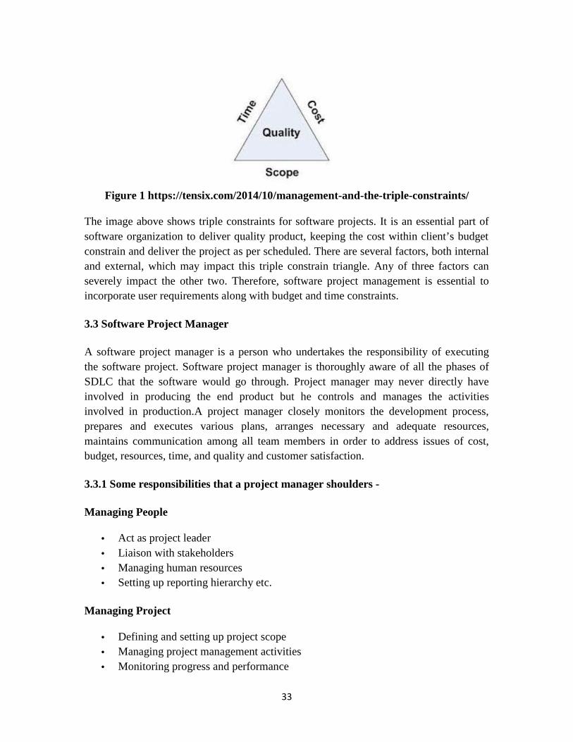
33
Figure 1 https://tensix.com/2014/10/management-and-the-triple-constraints/
The image above shows triple constraints for software projects. It is an essential part ofsoftware organization to deliver quality product, keeping the cost within client’s budgetconstrain and deliver the project as per scheduled. There are several factors, both internaland external, which may impact this triple constrain triangle. Any of three factors canseverely impact the other two. Therefore, software project management is essential toincorporate user requirements along with budget and time constraints.
3.3 Software Project Manager
A software project manager is a person who undertakes the responsibility of executingthe software project. Software project manager is thoroughly aware of all the phases ofSDLC that the software would go through. Project manager may never directly haveinvolved in producing the end product but he controls and manages the activitiesinvolved in production.A project manager closely monitors the development process,prepares and executes various plans, arranges necessary and adequate resources,maintains communication among all team members in order to address issues of cost,budget, resources, time, and quality and customer satisfaction.
3.3.1 Some responsibilities that a project manager shoulders -
Managing People
Act as project leader Liaison with stakeholders Managing human resources Setting up reporting hierarchy etc.
Managing Project
Defining and setting up project scope Managing project management activities Monitoring progress and performance

34
Risk analysis at every phase Take necessary step to avoid or come out of problems Act as project spokesperson
3.4 Software Management Activities
Software project management comprises of a number of activities, which containsplanning of project, deciding scope of software product, estimation of cost in variousterms, scheduling of tasks and events, and resource management. Project managementactivities may include:
Project Planning Scope Management Project Estimation
3.4.1 Project Planning
Software project planning is task, which is performed before the production of softwareactually starts. It is there for the software production but involves no concrete activitythat has any direction connection with software production; rather it is a set of multipleprocesses, which facilitates software production.
3.4.2 Scope Management
It defines the scope of project; this includes all the activities; process need to be done inorder to make a deliverable software product. Scope management is essential because itcreates boundaries of the project by clearly defining what would be done in the projectand what would not be done. This makes project to contain limited and quantifiable tasks,which can easily be documented and in turn avoids cost and time overrun.
During Project Scope management, it is necessary to -
Define the scope Decide its verification and control Divide the project into various smaller parts for ease of management. Verify the scope Control the scope by incorporating changes to the scope
3.4.3 Project Estimation

35
For an effective management accurate estimation of various measures is a must. Withcorrect estimation managers can manage and control the project more efficiently andeffectively.
Project estimation may involve the following:
Software size estimation
Software size may be estimated either in terms of KLOC (Kilo Line of Code) orby calculating number of function points in the software. Lines of code dependupon coding practices and Function points vary according to the user or softwarerequirement.
Effort estimation
The managers estimate efforts in terms of personnel requirement and man-hourrequired to produce the software. For effort estimation software size should beknown. This can either be derived by managers’ experience; organization’shistorical data or software size can be converted into efforts by using somestandard formulae.
Time estimation
Once size and efforts are estimated, the time required to produce the software canbe estimated. Efforts required are segregated into sub categories as per therequirement specifications and interdependency of various components ofsoftware. Software tasks are divided into smaller tasks, activities or events byWork Breakthrough Structure (WBS). The tasks are scheduled on day-to-daybasis or in calendar months. The sum of time required to complete all tasks inhours or days is the total time invested to complete the project.
Cost estimation
This might be considered as the most difficult of all because it depends on moreelements than any of the previous ones. For estimating project cost, it is required toconsider -
o Size of softwareo Software qualityo Hardwareo Additional software or tools, licenses etc.o Skilled personnel with task-specific skills

36
o Travel involvedo Communicationo Training and support
Self Assessment /Exercise-I
1. What do you mean by project? List its characteristics?
2. Explain the steps involved in project management activities?
3. List the responsibilities of Project managers.
4. What are the various steps involved in Project estimation?
3.5 Software Project Scheduling Techniques: -
3.5.1 Work Breakdown Structure: - The Work Breakdown Structure (WBS) is used fordefining work packages and developing and tracking the cost and schedule for theproject. The work is broken down into tasks, each of which has a manager, a responsibleinstitution, costs and schedule, technical scope, and, to the extent possible, a specificgeographic piece of the machine. Each level 3 element has a Task Manager who isresponsible for the execution of the project plans for that element.
There are many ways of breaking downtheactivities in a project, but the most usual isinto:
- Work packages;- Tasks- Deliverable- Milestone.
A work package is a large, logically distinct section of work typically requiringat least12 months’duration and may include multiple concurrent activities independent of otheractivities but may depend on, or feed into other activities typically allocated to a singleteam.
A task is typically a much smaller piece of work or a part of a work package typicallyrequireing 3–6 person months and effort maybe dependent on other concurrent activitiestypically allocated to a single person.

37
A deliverable is an output of the project that canmeaningfully be assessed. Examples: – areport (e.g., requirements spec)– code (e.g., alpha tested product).Deliverables areindicators of progress.
A milestone is a point at which progress on theproject may be assessed. Typically, amajor turning point in the project. Examples: – delivery of requirements spec– delivery ofalpha tested code.
Figure2http://www.technologyuk.net/computing/project_management/work_breakdown_s
tructure.shtml
3.5.1.1 Uses of Work Breakdown Structure: -
- For dividing the project into phases.- For dividing the project into responsibility area within the organization.- For dividing the schedule of the project into sub-schedules whose
interrelation are known.- For giving hierarchical outlining and coding for the work to be done.
3.5.2 Critical Paths- The pre-requisites and dependencies of WPs and tasks determine a critical
path: the sequence of dependencies in the project.- The critical path is the sequence of activities that takes the longest time to
complete.- Any delay to an activity in the critical path will cause delays to the overall
project.- Delays to activities not on the critical path need not necessarily cause
overall delays.

38
3.5.3 Gantt Chart: -A Gantt chart is a bar chart. A Gantt chart is useful for tracking andreporting progress, as well as for graphically displaying a schedule. Gantt charts are oftenused to report because they represent an easily understandable picture of project status.Gantt charts are not an ideal tool for project control. Gantt chart provides a graphicalillustration of a schedule that helps to plan, coordinate, and track specific tasks in aproject. The purpose of Gantt chart is to present a project that shows the relationship ofactivities over time. Gantt chart is a project planning tool that can be used to represent thetiming of tasks required to complete a project. Gantt charts are simple to understand andeasy to construct, therefore they are used by most project managers for all but the mostcomplex projects.
Figure 3https://www.ablebits.com/office-addins-blog/2014/05/23/make-gantt-chart-excel/
3.5.3.1 Advantages of Gantt Chart: -- Gantt charts are relatively east to create and maintain.- It is able to reflect the status of each project task at any point in time.- It is able to represent overlapping or parallel tasks
3.5.3.2 Disadvantages of Gantt Chart: -- It does not show a task interrelationship.- These are not ideal for project control.

39
3.5.4 PERT Chart: -A PERT chart is a project management tool used to schedule,organize, and coordinate tasks within a project. PERT stands for Program EvaluationReview Technique. A PERT chart presents a graphic illustration of a project as a networkdiagram consisting of numbered nodes (either circles or rectangles) representing events,or milestones in the project linked by labelled vectors (directional lines) representingtasks in the project. The direction of thearrows on the lines indicates the sequence of tasks. Pert chart depict task, duration anddependency information. Each chart starts with an initiation node from which the firsttask, originates. If multiple tasks begin at the same time, they are all started from thenodes out from the starting point. Each task is represented by a line, which states its nameor other identifier, its duration, the number of people assigned to it, and in some cases theinitials of the personal assigned. The other end of the task line is terminated by anothernode, which identifies the start of another task, or the beginning of any slack time, that iswaiting time between tasks.
Figure 4https://www.edrawsoft.com/template-simple-pert-chart.php
3.5.4.1 Uses of Pert Chart: -- The PERT network is straightforward in its concept and is supported by
software.- The PERT network is continuously useful to project managers prior to and
during a project.- The PERT network is a graphical representation of the project tasks help
to show the task interrelationship.- It allows scheduling and simulation of alternative schedules.
3.5.5 Activity Network: - An activity network is a labelled graph, with:

40
– nodes corresponding to activities,– arcs labelled with estimated times;– Activities are linked if there is a dependency between them.
3.6 Resource management: - All elements used to develop a software product may beassumed as resource for that project. This may include human resource, productive toolsand software libraries. The resources are available in limited quantity and stay in theorganization as a pool of assets. The shortage of resources hampers the development ofproject and it can lag behind the schedule. Allocating extra resources increasesdevelopment cost in the end. It is therefore necessary to estimate and allocate adequateresources for the project.
Resource management includes -
Defining proper organization project by creating a project team and allocatingresponsibilities to each team member
Determining resources required at a particular stage and their availability Manage Resources by generating resource request when they are required and
de-allocating them when they are no more needed.
3.7 Software Project Organization: -Organizing a Software Engineering projectinvolves developing an effective and efficient organizational structure for assigning andcompleting project tasks and establishing the authority and responsibility relationshipsamong the tasks.
Organizing involves:- Itemizing project activities required to achieve project objectives.
- Arranging project activities into logical clusters.
- Assigning groups of activities to various organizational entities.
- Delegating responsibility and authority needed to carry out the activities.
3.7.1 Major Issues in organizing: The major issues in organizing a software engineeringproject are as follows:
- It is difficult to determine the best organizational structure for a particularorganization and/or environment (for example, project, functional, matrix)to manage the project.
- An organizational structure may leave responsibilities for some projectactivities and tasks undefined or unclear.

41
- A matrix organizational structure is not accepted by many softwaredevelopment personnel.
- Many team leaders are expected to perform technically as well as managehis/her team.
3.7.2 Organizing Activities for a Software Project:
Activity Definition or ExplanationIdentify and group projectfunctions, activities, and tasks
Define, size, and categorize the project work.
Select organizational structures Select appropriate structures to accomplish theproject and to monitor, control, communicate, andcoordinate.
Create organizational positions Establish title, job descriptions, and jobrelationships for each project role.
Define responsibilities andauthority
Define responsibilities for each organizationalposition and the authority to be granted forfulfilment of those responsibilities.
Establish PositionQualifications
Define qualifications for persons to fill eachposition.
Document organizationaldecisions
Document titles, positions, job, descriptions,responsibilities, authorities, decisions,relationships, and position qualifications.
Table 1: Activities, definition of a software project
3.8 Project Organization Structures:There are three main types of organizational structures:
3.8.1Functional Project Organization:
- The project is organized into a number of functional groups; each groupaccomplishes its responsibilities and passes the project to the next group tocomplete other functional activities of the project. (Figure 5)
- Project management is distributed among functional groups managers.

42
Figure 5https://aacecasablanca.wordpress.com/2012/03/20/w9-0_rq_implementation-of-the-earned-value-management-process-for-housing-
project-the-process-steps-3-organization-and-responsibility-assignment/
3.8.2 Project Organization:- The project manager creates a project group for accomplishing all
activities of a given project (Figure 6).- Project manager has total authority over project.

43
Figure 6http://www.rff.com/project_orgchart.htm
3.8.2.1 Matrix Project Organization (the two boss system):
- A combination between the project and functional project organizations.(Figure 7)
- The project manager has the responsibility for managing and completingthe project.
- The functional managers provide the resources (employees) needed toconduct the project.
- Not a widely acceptable form of project organization.- Project authority must be clearly defined by upper management.

44
Figure 7.https://www.edrawsoft.com/project-organizational-chart.php
3.9 Software Project Teams:
There are three main types of software project teams:
3.9.1 The Democratic Team:
- Consists of 10 to 12 members- Decisions are made by consensus- Group leadership responsibility rotates- No permanent central authority- Rarely found today, however, sometimes used in research organizations.
3.9.2 The Chief Programming Team:- Consists of 3 or 4 permanent team members: chief programmer, backup
programmer, and librarian.- Other programmers or analysts are assigned as needed.- Chief programmer makes all technical and managerial decisions.- Rarely used today, because of difficulty in recruiting and training chief
programmers.

45
3.9.3 The Hierarchical Team (the controlled decentralized team, and projectteam):
- Has a top-down flow of authority- Project leaders manage senior engineers (senior programmers).- Senior engineers manage junior engineers (junior programmers).- Most commonly used team structure today.
3.10 Project Risk Management
Risk management involves all activities pertaining to identification, analyzing andmaking provision for predictable and non-predictable risks in the project. Risk mayinclude the following:
Experienced staff leaving the project and new staff coming in. Change in organizational management. Requirement change or misinterpreting requirement. Under-estimation of required time and resources. Technological changes, environmental changes, business competition.
3.10.1 Risk Management Process
There are following activities involved in risk management process:
Identification - Make note of all possible risks, which may occur in the project. Categorize - Categorize known risks into high, medium and low risk intensity as
per their possible impact on the project. Manage - Analyse the probability of occurrence of risks at various phases. Make
plan to avoid or face risks. Attempt to minimize their side-effects. Monitor - Closely monitor the potential risks and their early symptoms. Also
monitor the effects of steps taken to mitigate or avoid them.
3.10.2 Project Execution & Monitoring
In this phase, the tasks described in project plans are executed according to theirschedules. Execution needs monitoring in order to check whether everything is goingaccording to the plan. Monitoring is observing to check the probability of risk and takingmeasures to address the risk or report the status of various tasks.
These measures include -

46
Activity Monitoring - All activities scheduled within some task can be monitoredon day-to-day basis. When all activities in a task are completed, it is considered ascomplete.
Status Reports - The reports contain status of activities and tasks completedwithin a given time frame, generally a week. Status can be marked as finished,pending or work-in-progress etc.
Milestones Checklist - Every project is divided into multiple phases where majortasks are performed (milestones) based on the phases of SDLC. This milestonechecklist is prepared once every few weeks and reports the status of milestones.
3.10.3 Project Communication Management
Effective communication plays vital role in the success of a project. It bridges gapsbetween client and the organization, among the team members as well as other stakeholders in the project such as hardware suppliers.
Communication can be oral or written. Communication management process may havethe following steps:
Planning - This step includes the identifications of all the stakeholders in theproject and the mode of communication among them. It also considers if anyadditional communication facilities are required.
Sharing - After determining various aspects of planning, manager focuses onsharing correct information with the correct person on correct time. This keepseveryone involved the project up to date with project progress and its status.
Feedback - Project managers use various measures and feedback mechanism andcreate status and performance reports. This mechanism ensures that input fromvarious stakeholders is coming to the project manager as their feedback.
Closure - At the end of each major event, end of a phase of SDLC or end of theproject itself, administrative closure is formally announced to update everystakeholder by sending email, by distributing a hardcopy of document or by othermean of effective communication. After closure, the team moves to next phase orproject.
3.10.4 Configuration Management
Configuration management is a process of tracking and controlling the changes insoftware in terms of the requirements, design, functions and development of the product.
IEEE defines it as “the process of identifying and defining the items in the system,controlling the change of these items throughout their life cycle, recording and reporting

47
the status of items and change requests, and verifying the completeness and correctnessof items”.
Generally, once the SRS is finalized there is less chance of requirement of changes fromuser. If they occur, the changes are addressed only with prior approval of highermanagement, as there is a possibility of cost and time overrun.
Baseline
A phase of SDLC is assumed over if it baseline, i.e. baseline is a measurement thatdefines completeness of a phase. A phase is baseline when all activities pertaining to itare finished and well documented. If it was not the final phase, its output would be usedin next immediate phase.
Configuration management is a discipline of organization administration, which takescare of occurrence of any change (process, requirement, technological, strategically etc.)after a phase, is baseline. CM keeps check on any changes done in software.
3.10.5 Change Control
Change control is function of configuration management, which ensures that all changesmade to software system are consistent and made as per organizational rules andregulations.
A change in the configuration of product goes through following steps -
Identification - A change request arrives from either internal or external source.When change request is identified formally, it is properly documented.
Validation - Validity of the change request is checked and its handling procedureis confirmed.
Analysis - The impact of change request is analysed in terms of schedule, costand required efforts. Overall impact of the prospective change on system isanalysed.
Control - If the prospective change either impacts too many entities in the systemor it is unavoidable, it is mandatory to take approval of high authorities beforechange is incorporated into the system. It is decided if the change is worthincorporation or not. If it is not, change request is refused formally.
Execution - If the previous phase determines to execute the change request, thisphase take appropriate actions to execute the change, does a thorough revision ifnecessary.

48
Close request - The change is verified for correct implementation and mergingwith the rest of the system. This newly incorporated change in the software isdocumented properly and the request is formally being closed.
Self Assessment /Exercise-II
1. Explain the teams used for software project.
2. List the organizing activities for a software project.
3. Explain the uses of Pert chart.
4. Discuss the various advantages & disadvantages of Gantt Chart.
5. The process each manager follows during the life of a project is known asa) Project Managementb) Manager life cyclec) Project Management Life Cycled) All of the mentioned.
6. Which of the following is not project management goal?a) Keeping overall costs within budget.b) Delivering the software to the customer at the agreed time.c) Maintaining a happy and well-functioning development team.d) Avoiding costumer complaint.
7. Quality planning is the process of developing a quality plan fora) teamb) projectc) customersd) project manager.
8. Project managers have to assess the risks that may affect a project.a) Trueb) False
9. Which of the following is not considered as a risk in project management?a) Specification delaysb) Product competitionc) Testingd) Staff turnover
10. Which of the following expects cost estimation from SRS document?

49
a) Project Managerb) User documentation writerc) Software developersd) Maintenance engineers.
11.) What is Software?a) Set of computer programs, procedures and possibly associated document
concerned with the operation of data processing.b) A set of compiler instructionsc) A mathematical formulad) None of above.
12) Management of software development is dependent upon?a) Peopleb) Productc) Process
d) All of above
13) Gantt chart is a……………….a) Scheduling Techniqueb) Project.c) Effort time.d) Cost Estimation.
14) Types of Software Project Team are?a) 5b) 2c) 4d) 3
3.11Summary: -
Responsibilities of a project manager can be classified into two broad classes: - Project planning, and Project monitoring and control.
Project planning activities are undertaken before any development activity starts. Project planning activities: estimation, scheduling and staffing. Project monitoring and control activities are undertaken after the development
work starts. Software configuration is the state of deliverable items at any point in time.

50
3.12 Glossary: -
Baseline- A phase of SDLC is assumed over if it baselines, i.e. baseline is a measurementthat defines completeness of a phase. A phase is baseline when all activities pertaining toit are finished and well documented. If it was not the final phase, its output would be usedin next immediate phase.
Configuration management- It is a discipline of organization administration, whichtakes care of occurrence of any change (process, requirement, technological, strategicallyetc.) after a phase, is baseline. CM keeps check on any changes done in software.
Change control- It is function of configuration management, which ensures that allchanges made to software system are consistent and made as per organizational rules andregulations.
Risk management- It involves all activities pertaining to identification, analysing andmaking provision for predictable and non-predictable risks in the project.
Project - A project is well-defined task, which is a collection of several operations donein order to achieve a goal (for example, software development and delivery).
A work package is a large, logically distinct section of work typicallyrequiring at least12 months’ duration and may include multiple concurrent activities independent of otheractivities but may depend on, or feed into other activities typically allocated to a singleteam.
A task is typically a much smaller piece of work or a part of a work package typicallyrequireing 3–6 person months and effort maybe dependent on other concurrent activitiestypically allocated to a single person.
3.13 Solutions to Exercises I & II: -
Exercise-I
1. What do you mean by project? List its characteristics?
A project is well-defined task, which is a collection of several operations done in order toachieve a goal (for example, software development and delivery). A Project can becharacterized as:
Every project may have a unique and distinct goal. Project is not routine activity or day-to-day operations.

51
Project comes with a start time and end time.
2. Explain the steps involved in project management activities?
Project management activities may include:
Project Planning Scope Management Project Estimation
3. List the responsibilities of Project managers.
Managing People
Act as project leader Liaison with stakeholders
Managing Project
Defining and setting up project scope Managing project management activities
4.What are the various steps involved in Project estimation?
For an effective management accurate estimation of various measures is a must. Withcorrect estimation managers can manage and control the project more efficiently andeffectively.
Project estimation may involve the following:
Software size estimation Effort estimation Time estimation Cost estimation
Exercise-II
1. Explain the teams used for software project.
There are three main types of software project teams:
a) The Democratic Team:

52
b) The Chief Programming Team:
c) The Hierarchical Team (the controlled decentralized team, and project team):
2. List the organizing activities for a software project.
Activity Definition or ExplanationIdentify and group projectfunctions, activities, and tasks
Define, size, and categorize the project work.
Select organizational structures Select appropriate structures to accomplish theproject and to monitor, control, communicate, andcoordinate.
Create organizational positions Establish title, job descriptions, and jobrelationships for each project role.
Define responsibilities andauthority
Define responsibilities for each organizationalposition and the authority to be granted forfulfilment of those responsibilities.
Establish PositionQualifications
Define qualifications for persons to fill eachposition.
Document organizationaldecisions
Document titles, positions, job, descriptions,responsibilities, authorities, decisions,relationships, and position qualifications.
3. Explain the uses of Pert chart.
Uses of Pert Chart: -- The PERT network is straightforward in its concept and is supported by
software.- The PERT network is continuously useful to project managers prior to and
during a project.- The PERT network is a graphical representation of the project tasks help
to show the task interrelationship.- It allows scheduling and simulation of alternative schedules.
4. Discuss the various advantages & disadvantages of Gantt Chart.
Advantages of Gantt Chart: -- Gantt charts are relatively east to create and maintain.- It is able to reflect the status of each project task at any point in time.- It is able to represent overlapping or parallel tasks
Disadvantages of Gantt Chart: -

53
- It does not show a task interrelationship.- These are not ideal for project control.
Solutions to MCQ-
5. c 6. d 7. b 8. b 9. c 10. a 11. a 12.d 13. a 14.d
3.14 Bibliography/References/Suggested Readings
1. Roger Pressman, “Software Engineering: A Practitioners Approach,(6th Edition),McGraw Hill, 1997.2. Sommerville, ”Software Engineering, 7th edition”, Adison Wesley, 1996.3. Watts Humphrey,” Managing software process”, Pearson education, 2003.4. James F. Peters and Witold Pedrycz, “Software Engineering – An EngineeringApproach”, Wiley.5. Pankaj Jalote, “An integrated approach to Software Engineering”, Springer/Narosa.6.https://www.cs.umd.edu
3.15 Model Questions: -
1. What is the need of software project management?
2. What do you mean by software project manager?
3. What are the various software project scheduling techniques?
4. Explain the major issues involved in organizing the Software project?
5. What are the various activities involved in risk management process?
6. Discuss Configuration management.

54
Lesson No. 4:- Software Measurement and Metrics
4.0 Objectives
4.1 Introduction
4.2 Software Measurements
4.2.1 Measurement/Metric: - Characteristic
4.2.3 Software Measurement process
4.2.4 Software Measurement- Challenges
4.2.5 Reasons of Challenging Measurement/Metrics
4.2.6 Role of Metrics and Measurement
4.3 Types of Metrics
4.4 Effort Estimation
4.5 Function Points
4.6 Lines of Code
4.7 Function Points – Pros & Cons4.7.1 Pros4.7.2 Cons4.8 Lines of Code – Pros & Cons4.8.1 Pros4.8.2 Cons4.9 Function Point Vs Lines Of Code.4.10 Summary4.11 Glossary4.12 Answers to check your progress/self assessment questions4.13 References/ Suggested Readings4.14 Model questions
4.0 ObjectiveStudent should be able to
Define measurement and metrics in software engineering.
Should be able to analyse and explain the essential characteristics of each.
Should be able to identify the required elements of a given metric, and their
interrelationship among elements of metrics.
55
Should be able to draw comparison between different metrics.
Should be able to calculate the value of metrics and effort estimations.
4.1 Introduction
The Need for Software Measurement/ Metrics
As, the softwares were suffering from software crisis, the need of the hour was to define a
methodology so as to make more accurate schedule of softwares and cost estimates,
improved quality products, and more productivity. These can be achieved by effective
strategy of software management and control measures. Such management and quality
control measures can only be achieved if we have a method of measuring the software.
The traditional software management methodologies are ineffective because software
development is extremely complex. Software engineers require well-defined, reliable
methods of either the process or the product to help and evaluate development of a
product so, effective, quality oriented, planned methodology was not difficult to achieve,
and hence the role of software measurement comes into existence.
4.2 Software Measurements
The essential component in day to day life from scientific to engineering discipline
consists of measurements. Practical implementation of applications would not be possible
without measurements which gives an idea about proper management and planning.
Measurements are must from qualitative to quantitative planning, monitoring and
controlling various productions from Qualitative and Quantitative perspectives, analysis
cost and its benefits, especially when new techniques are developed or introduced.
Industrial software development requires the implication of various software engineering
methods and methodologies that are impressive and effective, i.e., they allow
organizations to develop quality assured software products efficiently and optimize
production resources to their best.
Definition of Measurement/Metric:- Measurement can be defined as mapping from the
empirical world to relational world. Measurement is number or symbol assigned to an

56
entity, in which mapping is done in order to characterize an attribute. Such
assignment of numbers to an entity is made according to unambiguous condition.
4.2.1 Measurement/Metric: - Characteristics
Reliable- The major characteristics of good measurement is its reliability, i.e.
output or outcome of a measurement process should be reliable.
Valid- The measurement process must be valid.
Sensitive- The measurement process must show variations according to
responses when there exists some stimulus or any kind of situation.
In the context of software engineering , measurement is the never ending process of
defining, analysing data in software development process and its products in order
to evaluate and control the process and its defined products , and to generate
meaningful information so as to improve that process and its products . Quality software
products cannot be building, without measurements. So for achieving the basic
management measurement is crucial.
4.2.2 Software Measurement process
The Process of measurement should be an orderly method and should be able to quantify
and adjust and ultimately lead to improvement of a process. Data is collected based on
known analysis and development issues, and queries. Such data is analyzed with respect
to the software development process and products. The major components of any
measurement process are:-:
Define Issues for measurement clearly
Process the data in Graphical or tabular form.
Provide insight to development issues
Use of analytical results to implement process improvements and identify new
problems Fig.4.1 describes the measurement process. The activities required to
design a measurement process using this architecture are:
Developing the measurement process.

57
Planning the process on projects and documenting procedures.
Process implementation on projects by executing the plans and procedures.
Process improvement by evolving plans and procedures .
Fig.4.1: Software Measurement- Challenges
4.2.3 Software Measurement- Challenges
The Vital thing in most software development method is unambiguous measurements.
The standardized measurement should:-
Have common baseline as a measurement
Have a point of reference in measuring software so as to verify and evaluate the
measuring results.
4.2.4 Reasons of Challenging Measurement/Metrics

58
Software is a not a tangible product:It is a product which when compared to other
industry oriented products, is usually measured in terms of size, complexity,
design methodologies, testing techniques and applications etc.
There is very low judgment of specific measures of software attributes.
Development in software is much more complex as all models to be considered
are difficult to validate.
Measurements May vary from project to project and form organization to
organization. Measurement of one project may not usually work for other.
4.2.5 Role of Metrics and Measurement
Measurement is composed of one or more data points.
A software metric is related to individual measures in different ways (e.g., the
average number of errors found per review )
Measurements are categorized in two ways: direct measures and indirect
measures.
Direct measures include lines of code (LOC) produced, execution speed, memory
size, and defects reported over some set period of time. Indirect measures of the
product include functionality, quality, complexity, efficiency, reliability,
maintainability.
The major purpose of metrics at any point during a development project is to
provide qualitative and quantitative information to the management process so
that the information can be used effectively and can control the development
process. There is hardly any metric that is developed for requirements.
Check your progress/Self Assessment Questions
Q1: What are metrics?
________________________________________________________________________
________________________________________________________________________
________________________________________________________________________

59
Q2: List the desirable characteristics of a Software Metric?
________________________________________________________________________
________________________________________________________________________
________________________________________________________________________
4.3 Types of Metrics
Process and project metrics quantitatively measure the inner detail, so as to gain insightknowledge about the efficiency of the projects conducted, using various processframeworks.. In managing projects , the primary concern is with quantitative andqualitative metrics. There are various reasons for measuring these products, andresources. (to evaluate, characterise, make decisions etc)
Process and Project Metrics
Metrics are applied so as to gain knowledge about process descriptors or informationcan be ascertained.
Some Process metrics gives indicating information that lead to long term processquality improvement
Project metrics enable a manager too Evaluate the status of project under development.o Track various potential risks arising at different phases.o Identify problems at early stageso Adjust various tasks or work flows.
Process Metrics
Private Process metrics : They are those metrics that are developed by privateorganizations and are only known to the individual or team concerned.
Metrics are used to enable organizations to make various changes to improve thesoftware process quality.
Metrics should not be used to evaluate the performance of individual personals. Statistical software process improvement helps the organization to discover where
they are strong.
Project Metrics
Team uses software project metrics to know project technical assessment andworkflows.

60
Project metrics are used to reduce development schedules and delays, mitigate manyfuture risks, and assess the quality of product.
Every project should measure its inputs and deliverables.
Size-Oriented Metrics
Derived by normalizing (e.g. defects or human effort) associated with the product orproject by LOC that is Lines Of Code.
Size oriented metrics are widely used but their validity and applicability is widelydebated.
Function-Oriented Metrics
Function points are calculated from direct measures of the information domain of abusiness software application and assessing its complexity.
Once computed function points are used like LOC to normalize measures for softwareproductivity, quality, and other attributes.
The relationship of LOC and function points depends on the language used toimplement the software.
Relationship between Line Of Code and Function Point Metrics
Programming language decides the relationship between lines of code and functionpoints.
Function Point and LOC-based metrics are accurate technique to measure effort andcost.
Lines Of Code and Function Points are used for estimating and developing a base.
OO Metrics
Count of scenario scripts (cSS) Count of key classes (cKC) Count of support classes (e.g. UI classes, database access classes, computations
classes, etc.) Average number of support classes per key class Count of subsystems (CSUB)
Use Case-Oriented Metrics

61
Describe (indirectly) user-visible functions and features in language independentmanner
Number of use case is directly proportional to LOC size of application and number oftest cases needed
However use cases do not come in standard sizes and use as a normalization measureis suspect
Use case points have been suggested as a mechanism for estimating effort
WebApp Project Metrics
Static Web pages Count(Csp) Dynamic Web pages Count (Cdp) Customization index: C = Csp / (Cdp + Csp) Internal page link Count Persistent data objects count External systems interfaced count Static content objects Count Dynamic content objects count Executables functions count
Software Quality Metrics
Quality of product comes from three perspectives (product operation, productrevision, product modification).
Quality factors operation, revision etc are there. Factors that require measure include:
o correctness (defects per KLOC)o maintainability (mean time to change)o integrity (threat and security)o usability (easy to learn, easy to use, productivity increase, user attitude)
Removal efficiency in defects (DRE) is a measure of the filtering ability of the qualityassurance and control activities as they are applied throughout the process framework
DRE = E / (E + D)
E = number of errors found before delivery of work product
D = number of defects found after work product delivery
4.4 Effort Estimation
It is an important activity in the early stages of software development. Software size, be it
Function Points or Lines of Code, plays a main role in this process, and forms the basis of

62
number of metrics to measure various aspects of the software, through the development
of a project. However, measuring the size of software becomes difficult. There are many
sizing measures in practice such as classes, programs, modules and so on, however Lines
of Code and Function Points are most widely used. Following sections explain these two
measures in brief.
4.5 Function Points (FP)This is basically structured and objective method for measuring size of software by
functional quantification given to the user, based on the requirements and logical design.
Such technique breaks into small components so they can be better analysed. Function
point method can be applied to development projects etc. such External Inputs (EIs),
External Outputs (EOs), External Inquiries (EQs), Internal Logical Files (ILFs) and
External Interface Files (EIFs). First three are transactional function Types and last two
are data function types. Function Point Analysis consists of performing the following
steps:
Determine the number of function point
Determine the application boundary
Examine rate transactional function types and calculate Unadjusted Function
Point count (UFP)
Identify data function and calculate their contribution to the UFP
Detect Adjustment Factor (AF) .
Finally, calculate the adjusted Function Point .
4.5.1 External Input (EI)External Input is simple , single atomic process in which data crosses the boundary from
external envoirment to internal .
4.5.2 External Output (EO)External output act as a boundary from internal to external. It updates internal logical file
and creates reports.
4.5.3 External Inquiry (EQ)

63
External Inquiry is a simple single process with input and output that leads to retrieval of
data from one or more internal logical files and external interface files.
4.5.4 Internal Logical File (ILF)Internal logical file is present in the application boundary, and is maintained through
External Inputs.
4.5.5 External Interface File (EIF)It is an identifiable group of logically related data that is used for reference. The data
resides outside and is maintained by external application boundary.
4.5.6 Rating the Transactional and Data Function TypesIndentified Components is assigned a rating (as Low, Average, and High). Transactional
Function Types are given the rating depending upon the number of Data Element Types
(DET), File Types Referenced (FTR) associated with them.
4.5.7 General System Characteristics (GSCs)There are 14 General system characterstics which leads to Value Adjustment
factor(VAF). Data processing, Performance measures , Heavily usedconfiguration. The degree of influence of each characteristic has to be determinedas a rating on a scale of 0 to 5 as defined below.
For no influence- 0 points
For Incidental influence- 1point
Moderate influence- 2 pints
Average influence- 3points
Significant influence- 4 points
Strong influence throughout- 5points
Degrees of Influence (DI) are calculated by totalling up all the ratings. Now, Value
Adjustment Factor is calculated using the formula:
AF = 0.65 + DI/100
4.5.8 Total FP NumberDetermining the Unadjusted Function Point count (UFP) out of transactional and data
function types, and calculating the Value Adjustment Factor (VAF)
FP = Unadjusted Function Point count (UFP) * Value Adjustment Factor (VAF)

64
4.6 Lines of CodeLines of code is a software metric used for measuring the length of software program or
software. LOC measures the effort that will be needed to develop a program, as well as to
estimate productivity once the software is produced. Software size measure is done by the
number of lines of code :-
Two types of measures are there:-
1. Physical Line of Code
2. Logical Line of Code
1. Physical LOC is a count of "non-blank, non-comment lines" in the text of the
program's source code.
2. Logical LOC to measure the number of "Lines", but definitions different from different
language
4.7 Function Point Metrics – Pros & Cons4.7.1 ProsFunction Point is best method for determining size of the software under consideration.,
(a) Comparison: As function point metric measures the system from functional
perspective, it is not only language independent but hardware/software
independent. This metric can be used to make a comparison with other tools,
environments or language, whether the language is more productive than other.
(b) Aid in Monitoring :
This metric provides a method to monitor scope creep. FP counts can be
compared after all the phases of system design are over. The FP count designed
and delivered can be compared. With the growth of project there is a software
creep.
(c) Contract Negotiations:. It becomes easy for customer to explain to vendor the
functionality level, key attribute to be delivered. These are used with fixed price

65
contracts. It becomes clear what will be delivered. For vendor it becomes easy to
calculate cost, effort by using metric like function point.
(d) Volatility handling: Function points are directly calculated from the requirements so
these bring early project cost estimation, effort required, schedule of project and hence
show the current status of requirements completeness. As we add new features, cost,
effort and schedule will grow accordingly. If organization removes some feature,
function point metric is capable of handling it and show the true status.
(e) Historic Data: Once project size and the scope of the project is agreed, project
manager calculate the appropriate estimate by using previous data. As Function point is
independent of language and tools, data from previous projects can be used to produce
consistent outputs, unlike Lines of Code data which is very much attached to languages
requiring many other parameters to be considered.
(f) Better Communication Managment: Function Point can greatly enhance
communications with higher management since it communicates in terms of
functionality rather than any processing details, technical issues, or code. Furthermore,
Function Points are easily understood by the non-technical user. This helps communicate
sizing information to a user (or customer) as well.
(g) Benchmarking: As Function Point is considered as language independent,
development methodology and technology aspects etc, Function Point is considerd to be
a tool for benchmarking across organisations and companies.
4.7.2 ConsFPA does have many disadvantages. However, organizations can easily overcome these
problems by practicing FPA consistently over a period of time.
(a) Manual Work: Manual work in counting the various functions in FP is more.
(b) Requires Significant Detail: Detail is required for estimating the software size of
Function Points. Information on databases, enquires, inputs, outputs and even records are
required to perform Function point.

66
(c) Requires Experience: Experience is required to handle details in FP, as it inherently
requires sufficient knowledge of the counting methods.
4.8 Lines of Code – Pros & Cons4.8.1 Pros(a) Automatic Counting:-Loc is a physical entity and can be automatically computed.
Utilities can be developed for automatic computing.
(b) Intuitive metric:- Loc Metric behaves as intuitive metric for measuring the size of
software and visualized effect. Function point is a physical metric. In this way Loc
behaves as easy programming methodology.
4.8.2 Cons(a) Missing Accountability: Lines of code metric suffers from basic problems. The most
important, it is completely difficult to measure the productivity of a candidate project
with the outcome of one of the phases.
(b) Missing Cohesion in Functionality: Effort is much more correlated with FP and
Functionality is less correlated with functionality.i.e developers may develop the same
functionality with small code.
(c) Experienced Developer: Same logic may vary from developer to developer
methodology of working based on the experience and affects the Lines of code count. A
developer experience may affect functionality and can change the line of code.
(d) Language Difference: Suppose there are two applications to be developed that
provide the same functionality (screens, reports, databases). First applications are written
in C++ and the other one is Perl. The number of function points would be exactly the
same, but aspects of the two will be different. The lines of code to develop will certainly
be different for developing same functionality. And hence the effort required to develop
will also differ. (hours per function point).
(e) Enhanced GUI Tools: Enhancement of GUI-based languages/tools such as Visual
Basic, most of development is carried by drag-and-drop tools, in this method
programmer usually writes no piece of code. Counting the lines of code is difficult in this

67
case. Such difference leads to larger variations in productivity and metrics with respect
to various languages, making the Lines of Code.
(g) OO Development: In Object oriented methodology , Lines of Code does not makes
any sense development where everything is treated in terms of Objects and classes . FPA
is more Connected with Object-Oriented software development.
(h) Many Languages Issue: In todays world, one language is no longer used for
development. Often, different languages are used depending upon the ambiguity and
requirements. Tracking and analysisng problems becomes difficult.
4.8 Function Point vs Lines Of Code
Parameters Function Point Lines of code
Count Easier to count a function point for anysystem which is present or yet to bedeveloped.
Difficult to count lines of codes, it maybe erroneous about 60-70% .
Estimation Effort and cost estimation isindependent of Function point. Itdepends on the average productivity ofthe team.
However, Function Point is not goodfor measuring the maintenance effort.
Line of code for estimating the effortand cost makes it dependent ontechnology and skill set of the personimplementing the software rather onproductivity
SelectionmechanismforTechnology
Function Point Analysis can be used todetermine whether the tool is effectiveor not within an organization .
Loc is difficult and erroneous , difficultto use the LOC technique for technologyselection because it is difficult toestimate amount of lines of code .
Metrics Function Point aids in deriving meaningof software metrics such asproductivity, software quality, defectdensity etc.
These metrics are independent ofdesign and technology and wouldremain same.
Not Suitable for metrics such asproductivity, software quality as theamount of LOC is negatively correlatedwith design efficiency.
.

68
Check your progress/Self Assessment Questions/ Multiple choice Questions
Q3. What are process metrics?
Q4. ____________ and ____________ are the two types of measures of lines of code
metric.
Q5. There are _______ general system characteristics which leads to Value Adjustment
factor(VAF) in fuction point metric.
Q6. Which of the following does not affect the software quality and organizational
performance?
a) Market
b) Product
c) Technology
d) People
Q7. The intent of project metrics is:
a) minimization of development schedule
b) for strategic purposes
c) assessing project quality on ongoing basis
d) both a and c
Q8. Which of the following is the task of project indicators:
a) help in assessment of status of ongoing project.
b) track potential risk
c) both a and b
d) none of the mentioned
Q9.Which of the following is not a direct measure of SE process?
a) Efficiency
b) Cost
c) Effort Applied
d) All of the mentioned

69
Q10.In size oriented metrics, metrics are developed based on the
____________________.
a) number of Functions
b) number of user inputs
c) number of lines of code
d) amount of memory usage
Q11.Which of the following is not an information domain required for determining
function point in FPA ?
a) Number of user Input
b) Number of user Inquiries
c) Number of external Interfaces
d) Number of errors
4.10 Summary
The essential component in day to day life from scientific to engineering disciplineconsists of measurements. Measurement is number or symbol assigned to an entity,in which mapping is done in order to characterize an attribute. The Process ofmeasurement should be an orderly method and should be able to quantify and adjust,ultimately leading to improvement of a process. In the context of software engineering ,measurement is the never ending process of defining, analysing data in softwaredevelopment process and its products in order to evaluate and control the processand its defined products , and to generate meaningful information so as to improvethat process and its products . Quality software products cannot be built withoutmeasurements. Process and project metrics quantitatively measure the inner detail, so asto gain insight knowledge about the efficiency of the projects conducted, using variousprocess frameworks. There is a wide variety of size oriented, function oriented, objectoriented, quality oriented metrics to guide and control the overall process of softwaredevelopment. Quality of product comes from three perspectives (product operation,product revision, product modification).
4.11 Glossary
Metric: It can be defined as mapping from the empirical world to relational world.

70
LOC: Lines of Code is a size metric to estimate software effort.
FP: Function point is functionality based metric used as LOC metric to estimate software
effort.
Process and Project Metrics: They are applied so as to gain knowledge about processdescriptors
4.12 Answers to Self assessment questions
Ans 1:-They are quantitative measure of management tools. They offer insight to the
effectiveness of software process and the projects that are conducted using the process as
a framing tool. Basic quality and productivity data are collected. The data is analysed and
compared with previous outputs.
Ans 2: - Following are the attributes of a software metrics-
1. Easy and simple-
2. Consistent and objective
3. Programming language independent.
4. An effective mechanism for quality feedback
Ans 3:- Process metrics are collected across all projects and over long periods of time for
making decisions. The basic concept is to provide techniques that lead to long term
software process improvement
Ans 4:- Physical LOC, Logical LOC
Ans 5: - 14
Ans 6:- a
Ans 7:- d
Ans 8: - c
Ans 9:- a
Ans 10: - c

71
Ans 11:- d
4.13 References/ Suggested Readings
"1. Roger. S. Pressman, Software Engineering - A Practitioner's Approach, 7th Edition,
McGraw Hill, 2010.
2. Rajib Mall, “Fundamental of Software Engineering “, 3rd edition, PHI, 2009.
3. Naseeb Singh Gill, “Software Engineering: Software reliability, testing and quality,
Khanna Book Publishing, 2011."
4.14 Model Questions
Q1. Explain the process of Software Measurement.
Q2.What is the need for Software Metrics Development?
Q3. Discuss the various types of process Metrics.
Q4. Elaborate the advantages and disadvantages of Function point metrics.
Q5. Compare and contrast Lines of Code and Function point metrics in the context of
effort estimation.

72
Lesson 5: Software Project Planning
5.0 Objective5.1 Introduction5.2 Software project planning
5.2.1 The software management plan (SPMP) document5.3 Software decomposition techniques.
5.3.1 Example5.3.2 Gantt Charts5.3.3 PERT Charts
5.4 Software sizing5.5 Problem based estimation techniques
5.5.1 LOC5.5.2 Function / Feature point metrics
5.6 Project based estimation5.6.1 Empirical Estimation Technique
5.6.1.1 Expert judgment Technique5.6.1.2 Delphi cost estimation technique
5.6.2 Heuristic estimation technique5.6.2.1 Basic Cocomo model5.6.2 Intermediate Cocomo model5.6.3 Complete Cocomo model
5.7 Summary5.8 Glossary5.9Answers to self-assessment questions5.10 References / suggested readings5.11 Model questions
5.0. Objectives
This lesson will add to our knowledge with basic introduction of software projectplanning. We will be able to estimate software project with cost and efforts. This lessonwill also enhance our knowledge about decomposing of software product so the projectsizing and staffing should be done on a right channel.
5.1. Introduction
Once we are done with feasibility study and we found the project to be feasible. Theplanning of software project starts. The chief of the project i.e. the software projectmanager took initiative and starts planning. All these activities should be done before weactually start working on the project. As easy as we plan our day a night before andexpect everything should be done as we have planned. A lot of exercises needs to beconsider to software project plan that we will study in this lesson

73
Figure 5.1: Software Project Plan
A lot of new terms are added in the diagram any how all of these terms are related tosoftware project planning. We will discuss them all in further topics.
5.2. Software Project Planning
The very basic & necessary thing to know is “software project management processbegins with project planning” and objective of software project planning is to provide anestimate for manager to know about resources, cost and schedules.
An informal definition of software project planning management is an ability to get workdone from others.
Here we will discuss things which are necessary in software project planning.
Estimates: A software project manager should estimate about following attributes.- Cost: How much money would be enough to develop this project.- Duration: The time to develop the project.- Efforts: Will the team do this work in fewer efforts or they need to apply
more efforts to complete project.

74
Estimates defines “Worst case & Best case”
Scheduling: How to break down the work, but resources & manpower is neededto complete the project.
Staffing: How many members would be enough in team to complete project.What will be the team structure?
Risk Resolution: If at any time any risk occurs, how it will be resolved & what areour plans to solve it.
Miscellaneous plans like Quality assurance, installation maintains etc.
Figure 5.2: Software Project Planning
Project planning has to be done with a lot of care & full attention because anythingthat goes wrong results in dis-satisfaction of customer. In today’s world where “Customeris king”, he/she has a lot of options to choose a software company from but once thecustomer is dissatisfied, t he company will not get work next time. So, the softwareproject manager has a lot of information and knowledge so that He / she would be able tocomplete software project with accuracy.
5.2.1. The software management plan (SPMP) document: -
Once the software project planning has been completed the manger has answersof a lot of things. SPMP document should discuss.
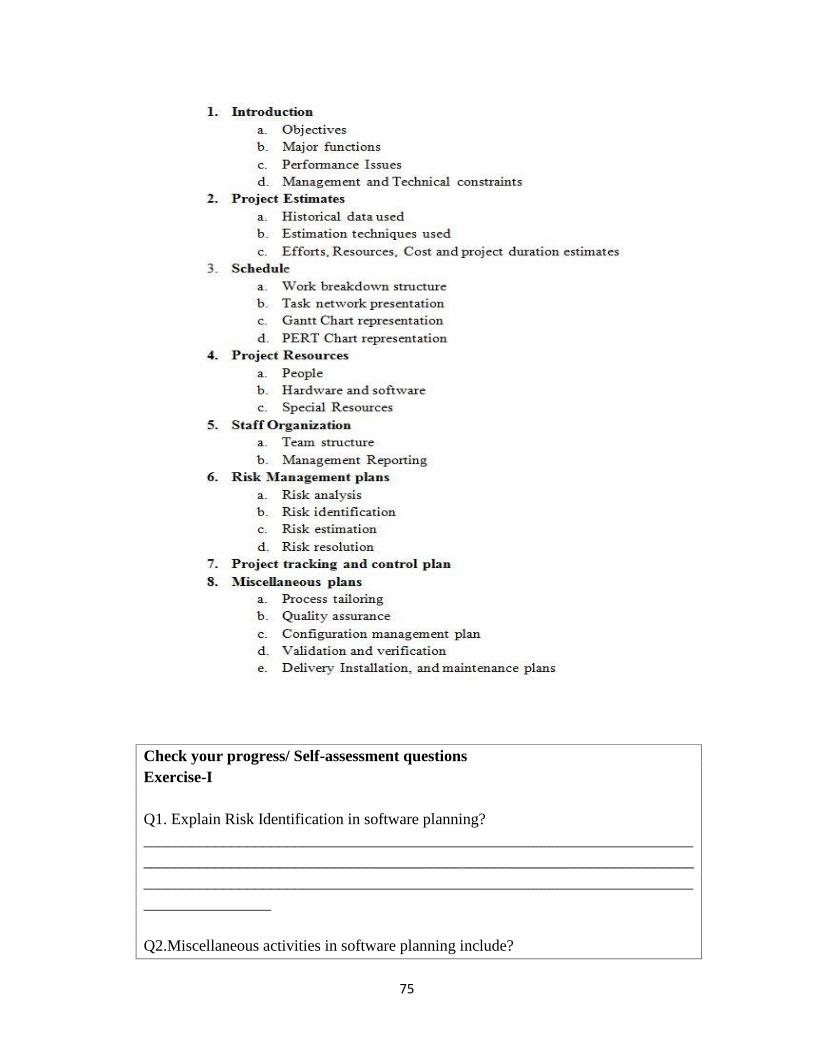
75
Check your progress/ Self-assessment questionsExercise-I
Q1. Explain Risk Identification in software planning?_______________________________________________________________________________________________________________________________________________________________________________________________________________________________
Q2.Miscellaneous activities in software planning include?

76
a. Quality assuranceb. Installationc. Deliveryd. All of above
Q3. SPMP is the outcome of software project planning.a. Trueb. False
5.3. Software Decomposition Techniques
As we learnt earlier that management is about “Getting work done by people”. Insoftware decomposition approach we decompose the work in such a way that softwareproject should get completed on time. A software project manager has followingresponsibilities.
1. Identify all the modules those need to be completed to finish project.2. Decompose the larger activities into smaller one’s3. Look for dependencies among modules.4. Estimate the time duration mandatory to complete module.5. Provide resources to modules.6. With software engineers do planning about starting and ending of modules.7. Find out the critical path.
In software scheduling a lot of tasks need to be done. A good software projectmanager break down the task in smaller activities which are assigned to differentengineers the benefit of assigning work in different engineers is that the smallermodules are built concurrently and fast. A lot of work break down structures are therelike.

77
Figure 5.4: Software Decomposition Techniques
Once the task is decomposed in smaller modules the manager looks fordependences among modules i.e. say we have modules A, B & C that need to be done forcompletion of project & all the modules are dependent on each other, then the module Ashould be completed first so that the work of module B get started followed by module C.
Later on resources will be allocated to the modules which is done by Gantt Chartonce it is done, PERT (Project evolution and review techniques) chart representation isto be developed.
5.3.1. Example
Here we are decomposing the bigger activity into multiple smaller modules & eachmodule is assigned a particular time period to complete as shown in the diagram.

78
Figure 5.4: Decomposition of larger activity into smaller activities
Arrows are representing the interdependences and thicker arrows are representing thecritical path .From diagram we can estimate the following thing.
The minimum time (MT) required completing the project.
The earliest start (ES) is time for starting the module. The latest start (LS) is the difference between.
LS = MT – ES The earliest finish time (EF)
EF = ES + duration of task. The latest finish (LF) time can be calculated by
LF = MT – Max of all path. The slack time (ST) is
ST = LS – EF is also known as float time
The critical task is done with zero stack time from the figure we can calculate.

79
5.3.2. Gantt chart
The resources required by the modules could be staff, hardware & anything else.Gantt chart represents the resources allocated to the modules. The name of Gantt chartwas derived from its developer Henry Gantt. Gantt chart is very useful in resourceplanning.
As shown in the figure
Figure 5.5 GANTT chart
Consider the previous example, the Gantt chart is based on bars where the shaded partrepresents the estimated time required to complete the module & the white part representsthe slack time.
5.3.3. PERT Chart
PERT (Project evaluation & review technique) instead to showing the eachmodule by a different bar. A PERT chart represents the modules statically. We consider

80
three terms in PERT charts, minimum, likely & maximum. Each module will have someminimum time to get complete, some likely time and some maximum time. Taking thesame example as shown in figure each module has three variants of time representingtheir time limits.
Figure 5.6 PERT chart
5.4. Software Sizing
Every one of us knows that units of measuring current, room temperature, thickness,length and a lot of things to measure but does anyone knows the unit to measure thesoftware size ? Here the question arise that how can be estimate the size of the softwareso that we tell customer about cost & resources.
Let us consider a situation say we are building a new house & the contractor told us thatthe approximate cost required to make this house is 3 lac rupees so how does contractorgets to know the cost. The contractor just gives us a rough review by calculating staff,resources re-novation and all other things. The cost may grow up to 3.25 lacs or even3.50 lacs so we will be all right with that, but what if this cost comes to 4 lacs definitelythis will pinch us because we have made up our budge according to 3 lacs. Anyhow wecan tolerate up to 3.50 lacs but not with 4 lacs. Obviously we will have a word withcontractor & contractor will tell us some points that why the cost has been raised so herewe are customer and 1 lac extra is pinching us.
Take the second side of coin you are a software project manager and with yourexperience you told to customer that the software project with cost up to 50,000 rupees,

81
so a figure is clear in customer’s mind but if it crosses more than 60,000 definitely thecustomer will have problem with it.
So, it is understood that software sizing should be done with expertise and a lot of thingsare to be considered in the process.
To accurately estimate the software size we have some techniques as under.
LOC(Lines of Code):
We can calculate the software size by its line of codes that will tell us the effortsneeded to prepare the software product. But some programmers add a lot of extra linesfor comments and starting of modules that will not give us proper efforts and cost toestimate the software size so a common criteria is made up to write the line of code sothat by which we can calculate the efforts and code.
Function point Metric:
It is a method to calculate the size of software project based on the formula.
FPM = (no. of inputs) x 4 + (no. of outputs) x 5 + (no. of inquires)x 4 + (no. of files) x 10 + (no. of interface) x 10.
Where number of inputs, outputs, inquires, files &interface depend on thesoftware project.
Learn from previous projects:
We can estimate the project size from the projects of same type which were madein the past time. Say if we had made up a project of School management system we knowthe size, efforts & cost of the project and now we got a new project of collegemanagement system which is new to us but we can estimate its size by studying theprevious project.
Expert Judgment Technique:
Here we call the experts & show them SRS (software requirement specification)and based on their experience and judgment we calculate the software size.
Delphi cost Estimation:
This approach over comes the problems with expert judgment technique wheneverything was open. Here each expert is called and given a form based on project. Ameeting is being carried on and co-ordinated by a coordinator. Experts fills the form andthen based on their forms the coordinator estimates the software size.

82
Some other techniques are
Check your progress/ Self-assessment questionsExercise-II
Q1. What are strengths and weakness of expert judgment technique?_______________________________________________________________________________________________________________________________________________________________________________________________________________________________
Q2.What is the formula to calculate function point metrics?_______________________________________________________________________________________________________________________________________________________________________________________________________________________________
Q3. Explain Gantt Charts.

83
________________________________________________________________________
5.5. Problem based estimation techniques
Based on the problems we can estimate the size of the software project, eventhough we know that the exact project size, cost is not accurately measured based on theproblem. We have some methods to find out the project cost & size based on problem wewill discuss these points one by one.
5.5.1. LOC(Lines of Code): -
The very simple & easiest method to find out the problem is the lines of code.This is a very popular approach used by software project managers In this approach wecalculate the number of lines which the programmers has written in coding based on thislines of coding we calculate the size of project. Following things are taken intoconsideration for LOC.
Comment lines are not counted
Header files are excluded Blank lines are ignored
Starting & ending of brackets is considered with lines.
Since it is a very simple method so a lot of problems may occur in this. Whensoftware project manager divides tasks into modules than modules into sub modulesdifferent software engineers works on these sub modules & each engineer has its ownway of work.
Many times it is seen that different style of programming is followed by softwareengineers which leads to incorrect information of LOC because the oneprogrammer who write a code in 5 lines & a programmer who write a code in 2lines will make a lot of difference in cost.
Approach 1 Approach 2//line 1 int a=10;//line 2 while (a<=10)//line 3 {//line 4 cout<<a;//line 5 }//line 6 a++;//line 7 cout<<endl;//line 8 getch();
//line 1 for (int a=1;a<=10;a++)//line 2 { cout<<a<<endl; }//line 3 getch();

84
Two different approaches for same output one approach took 8 lines & secondapproach look 3 lines, so the style of programming needs to be considered.
Problem size does not accurately tell the complexity of the project it onlycomputes the line of codes & not the functions / features of the project.
Programming language is another factor because different programminglanguages have different approaches where a code can be written in 2 lines inone language it is possible that another language took 8 lines for the same code.
5.5.2. Function / Feature point Metric: -
This approach was proposed by Mr.Albrecut in 1983. This approach overcomesmany problems of LOC metric where only lines of codes were considered to calculate thesoftware project effort. In this approach we look for features of software project, if morefeatures are added more will be the cost of the project.
For example: A simple hotel management software only books room and on check out itmakes bill but an another one not only performs the basic function of hotel but alsoentertains with games, good graphics, music, animation, tells about staff and has a lot ofother features that will definitely increase its cost & will be loved by hotel owners andmore demand of this software will come up.
Figure 5.7: Function point metric
Summing up, the software project with more features will require more effort. So the costis dependent on all the features & not the LOC only in this approach.

85
5.6. Project estimation techniques
Making an estimate for the project is the basic planning activity which tells the softwareproject manager about size & efforts to develop the project. These estimates not onlyhelps in finding the cost of the project but also useful in finding resources & planscheduling. Here we have broad category & project estimation techniques.
Figure 5.8 Project Estimation technique
5.6.1. Empirical Estimation Technique: -
As we have already discussed we have two popular estimation techniques
Expert judgment techniques Delphi cost estimation

86
5.6.1.1. Expert judgment Technique: -
It is the most widely used project estimation technique. This approach is very popularbecause in this approach we call an expert & tells him/her about our project. Expertstudies the SRS document & then makes an educated guess of the problem size. Adifferent expert follows different approach to calculate the cost and to find out the projectsize. For example some experts may consider the user interface & features of project tomake a guess about the cost & some experts may not consider these things.
5.6.1.2. Delphi cost estimation: -
Delphi cost estimation approach works in a different way. In this technique we call ateam of experts and a coordinator, and each of them is provided with SRS. After studyingSRS they are provided a form based on the project which may include software featuresLOC, UI & some other things. All the experts fill their form accordingly. Then theinformation filled in these form are compiled by the coordinator and then he/she makesan estimates about software project size and cost.
5.6.2. Cocomo Model (COnstructive, COst estimation MOdel)
Proposed by Mr. Boehm in 1981 based on this model the software project wasdivided into three categories.
Figure 5.9: Division of software projects

87
Mr. Boehm proposed that while developing a software product we should not onlyconsider characteristics of the product but also the staff (development team) anddevelopment environment. According to this model, the projects can be classified asfollows:
Organic: - A type of software project which is well understood, size of development teamis small and the team is well experienced in developing these types of projects.
Semidetached: -This type of software project is a little bit similar to one which wasdeveloped earlier by the team. The team consists of experienced people as well as un-experienced staff and team members are familiar with some aspects of the project.
Embedded:-A complex hardware situation, a totally new project, team members areexperienced.
5.6.2.1. Basic Cocomo: -The basic cocomo model provides nearby estimate of theproject by following expressions.
Efforts = a1 x (KLOC) a2PM
Tdev = b1 x (Efforts)b2PM
Where KLOC is the estimated size of product in kilo line of code
a1, a2, b1, b2 are constants.
Tdev is the time to develop the software product in person month.
According to this model
Estimates of development efforts:
Organic: Efforts = 2.4 (KLOC) 1.05 PM
Semidetached: Efforts= 3.0 (KLOC)1.12 PM
Embedded: Efforts = 3.6 (KLOC)1.20 PM
Estimates of development time:
Organic: Tdev 2.5 (Efforts) 0.38Months
Semidetached: Tdev = 2.5 (Efforts) 0.35 Months
Embedded: Tdev = 2.5 (Efforts) 0.32 Months

88
5.6.2.2. Intermediate CoCoMo: - In addition to basic cocomo intermediate cocomotakes into consideration about some more terms listed below
Product Computers
Personal Development environment
5.6.2.3 Complete CoCoMo: - This model adds
Database Part
Graphical user interface Part Communication Part
To make an estimate for the product size and cost.
Check your progress/ Self-assessment questionsExercise-III
Q1. Explain rules of counting efforts in LOC?_______________________________________________________________________________________________________________________________________________________________________________________________________________________________
Q2.Explain Delphi cost estimation technique?_______________________________________________________________________________________________________________________________________________________________________________________________________________________________
Q3. Which of the following formula is correct to calculate efforts in basic cocomomodel?a. Efforts= a1 x (KLOC) a2 PMb. Efforts= a1 x (LOC) a2 PMc. Efforts= a2 x (KLOC) a1 PMd. None of these
Q4.List down problem estimation techniques.__________________________________________________________________________________________________________________________________________

89
5.7. Summary: - In this lesson we have learnt that software planning is an important stepbefore development of software starts. A lot of exercises need to be done like scheduling,staffing, sizing, project estimates etc. to estimate the efforts and cost to develop softwareproduct.
We have also learnt that while developing software only project is not considered but alsothe development team and development environment is taken care off.
5.8 Glossary
Delphi cost Estimation: This approach over comes the problems with expert judgmenttechnique when everything was open. Here each expert is called and given a form basedon project. A meeting is being carried on and co-ordinated by a coordinator. Experts fillsthe form and then based on their forms the coordinator estimates the software size.SPP: Objective of software project planning is to provide an estimate for manager toknow about resources, cost and schedules.Gantt chart: represents the resources allocated to the modules.Cocomo Model: (COnstructive, COst estimation MOdel)
5.9. Answers to self-assessment questions
Exercise – I
Answer 1. There is always risk in software development because client at any point tellsthe modifications in software. Anyhow if something goes wrong the software managertries to overcome the risk and make it as much less as much he/she can.
He identifies the risk then estimates the risk and resolve the risk.
Answer 2. D
Answer 3. A
Exercise- II
Answer 1. It is the most widely used project estimation technique. This approach is verypopular because in this approach we call an expert & tell him/her about our project.Expert studies the SRS document & then makes an educated guess of the problem size. Adifferent expert follows different approach to calculate the cost and to find out the projectsize. For example some experts may consider the user interface & features of project tomake a guess about the cost & some experts may not consider these things.
Answer 2.

90
FPM = (no. of inputs) x 4 + (no. of outputs) x 5 + (no. of inquires) x 4 + (no. of files) x10 + (no. of interface) x 10.
Answer 3. The resources required by the modules could be staff, hardware & anythingelse. Gantt chart represents the resources allocated to the modules. The name of Ganttchart was derived from its developer Henry Gantt. Gantt chart is very useful in resourceplanning.
Exercise- III
Answer 1.
Comment lines are not counted
Header files are excluded Blank lines are ignored Starting & ending of brackets is considered with lines.
Answer 2.
Delphi cost estimation approach works in a different way. In this technique we call ateam of experts and a coordinator each of them are provided with SRS. After studyingSRS they are provided a form based on the project which may include software featuresLOC, UI & some other things. All the experts fill their form accordingly. Then theinformation filled in these form are compiled by the coordinator and then He/she makesan estimates about software project size and cost.
Answer 3. A
Answer 4. Lines of code
Function point metric
5.10 References / Suggested readings
1. Software Engineering: A Practioner’s approach, Roger S. Pressman, Fifth Edition,McGraw Hill publication.
2. Fundamentals of software Engineering, Rajib Mall, Second Edition, Prentice-Hall ofIndia Pvt. Ltd. New Delhi.
3. An integrated approach to software engineering, Pankaj Jalote, Third Edition, NarosaPublishing house.

91
5.11Model questions / Self-answering questions
List the major responsibilities of a software project manager.
1. What are relative advantages of using LOC and feature point metric in problembased estimation.
2. What is egoless programming? How it can be realized.3. Explain Cocomo model in detail.4. Suppose you are developing a software product in organic mode. You have
estimated the size of product to be 100,00 lines of codes. Compute the nominalefforts and development time.
5. Explain various types of project estimation techniques.

92
Lesson 6: Cost Estimation Models
6.0 Objectives
6.1. Introduction
6.2. Software effort estimation models
6.3. Cost estimation
6.4. Constructive cost model (COCOMO)
6.4.1 Basic Cocomo
6.4.2 Intermediate Cocomo
6.4.3 Detailed/Embedded Cocomo
6.5. Software equation
6.6. Summary
6.7. Glossary
6.8. Answers to self assessment questions
6.9. References/Suggested Readings
6.10. Model Questions
6.0 Objectives
Understanding the basics of software cost estimation and study the relation
between price and development cost of the software.
Defining the metrics used to measure software.
Elaborating the structure of software estimation.
Implementing Constructive cost model for cost estimation.
Understanding software equations
6.1 Introduction
With the change in time, lines of code of software are changing from thousand to
millions, and the software development team is increasing from single person to set of
experts, and completion of projects are converting from months to years. The mistakes in
cost estimation bring gap between software benefit and loss.
93
The project gets started with the continuous flow of instructions and finishes with the
complete resources and cash. The complete information about resources, cash, planning,
and control are under the supervision of project manager to achieve the objectives of the
project. The objective to complete the project is achieved with complete team work. And
every member of the team must realize his/her work and perform the task with full
dedication.
Once the estimates of the project are done they are not final. With the development of the
project the estimates also varies as per the project requirements. The prime concern is to
estimate the tasks to complete the project. Cost of the project is not an initial issue. As the
project progresses more information on project and process requirement is produced.
Software cost estimation is a complex activity that requires knowledge of key attributes
about project for which estimate is being constructed. Outcome of the project depends
upon the accuracy and relationship among the parameters. The parameters that reduce the
gap between profit and loss are:
- Size of source code, manuals, and specifications: Simple codes are easy to
process and remove errors. Complex codes take more time and effort to
understand and update which results in rise in cost and efforts.
- Rate at which requirements changes: Frequent changes in the project require
relative updates in software coding. The frequent updates in software bring
difference in profit and loss.
- Set of project activities: The activities of the software changes with change in
requirement. These activities get stable at the end of project. To estimate the cost
at the end of project is not practical.
- Comparing and estimating the cost and schedule of previous project with new
projects: The cost and schedule calculation of new project can be compared with
the similar last projects to find the positive or negative comparison.
- Simple decomposition technique to generate project cost and efforts: If the huge
project is divided into different modules, then the cost estimation will be
performed on individual models and at last all the modules will get integrated and
estimates can be calculated.

94
6.2 Software effort estimation models
Function point (FP) is a unit of measurement of software in software engineering to
express an amount of functionality provided to a user. Function point is a tool to measure
the size of the software. Line of code (LOC) metric measures the size of the software by
counting the number of lines in the software source code. Line of code calculates the
amount of effort required to develop software. Line of code per programmer-month
LOC/pm is calculating number of line of codes that are delivered, then divide the count
by total time in programmer-months required to complete the project.
Software estimation models are calculated by using the values of LOC and FP.
The effort estimate of the project is derived by the structure
E = A + B * (Size) c
A, B, and C are experimental constants that depends upon size and type of software
development,
E is effort in person-month, and
‘Size’ may be the code size (KLOC) or function point (FP) of software.
To calculate the effort estimate for the project with 25000 (25K) LOC, with the constant
A= 5.5, B=0.73, and C = 1.16 is
E = 5.5 + 0.73 * (25)1.16
= 5.5 + 0.73 * 41.84
= 5.5 + 30.5
E = 36 persons/month
6.3 Cost Estimation
The approximate measurement of cost of the project in terms of amount of time a person
works with efforts is known as Cost estimation. The cost estimation will determine which

95
features can be included within the project. The risk of the project is reduced when the
most important features are included at the beginning because the complexity of project
increases with its size. Probability of mistakes rises with increase in size of project. There
is direct affect of cost estimation on cost and schedule of project.
Total software project cost = software development labour cost + other labour cost
+ non-labour cost
Software development labour cost includes
1. Software engineering: Joint action done by software engineer, software
requirements, development code, software integration.
2. Software test engineers: Covers test engineering activities.
Other labour cost
i. Software Management and administration: Software managers and administrators
plan and direct the project.
ii. Software quality check and testing
Non-labour cost
i. Support and services provided in project development, such as workstations,
ground equipments, network and phone charges.
ii. Training
The project approval, project management, and project team understanding are done by
estimating the cost of the software
- Project approval: For every project there must be a decision by the organization to
undertake the project. Such decisions require an estimate of money and resources
required to complete the project.

96
- Project management: Project managers are responsible for planning and control of
project. Both activities require an estimate of the activities required to complete a
project and resources required for each activity.
- Project team understanding: For the project team members it is necessary that
each one understands individual role in the project and overall activity of the
project. The project task is generated by the cost estimation.
Self Assessment Questions/Exercise -I
Que1. Define various variables used in estimating the software cost. How the individual
variable is defines?
Ans:
________________________________________________________________________
________________________________________________________________________
Que2.List the reasons, why cost estimation process is undertaken?
Ans:
________________________________________________________________________
________________________________________________________________________
6.4 COCOMO Model (COnstructive COst MOdel)
COCOMO model allows software project manager to use regression formulae andestimate project cost and duration, with current and previous projects data. These data areanalyzed to discover formulae that were the best fit to the observations.
The explanation of COCOMO model is done in three levels, each level corresponds tothe detail analysis of cost estimation. The first level provides an initial rough estimate, thesecond level modified by using number of project multipliers, and the third level produceestimates for different phases of the project.
Project Level Description
Simple / Organic Well understood applications developed by small teams

97
Moderate / IntermediateMore complex projects where team members may have
limited experience of related systems
EmbeddedComplex projects where the software is part of a stronglycoupled complex of hardware, software, regulations, and
operational procedures.Table-1: Levels of COCOMO model with description
Hierarchy of COCOMO models
1. Basic COCOMO
2. Intermediate COCOMO
3. Embedded COCOMO
MODES
Organic Mode
Designed under simple environment using easy tools,
Copy the features of previous projects
Little innovative
Intermediate Mode
In-between between Organic and Embedded Modes
Modified by using number of project multipliers.
Embedded Mode
Strong rigid interface requirements
Densely innovative.
Hold all the features of intermediate version
6.4.1 BASIC COCOMO
Basic COCOMO model estimates the software development effort by using single
variable Delivery Source Instructions (DSI) and three software development modes. It is
used for small projects and only a few cost drivers are concerned. Cost drivers depend
upon project size mainly. It is useful when the team size is small.
The effort (E) and schedule (S) of the project are calculated as follows

98
Effort E = a * (KDSI) b* EAF Where KDSI is number of thousands of delivery
source instructions, ‘a’ and ‘b’ are constants.
Schedule S= c * (E) d , where E is the Effort and ‘c’, ‘d’ are constants.
EAF is called Effort Adjustment Factor which is 1 for basic COCOMO , this
value may vary.
Mode Effort Schedule
Organic E = 2.4 * (KDSI)1.05 TDEV = 2.5 * (E)0.38
Semidetached E = 3.0 * (KDSI)1.12 TDEV = 2.5 * (E)0.35
Embedded E = 3.6 * (KDSI)1.20 TDEV = 2.5 * (E)0.32
Table-2: Modes of COCOMO model with effort and schedule equations
Basic COCOMO is good for quick, early, rough order of magnitude estimates of
software costs
An example of basic COCOMO model
We estimate our embedded project will have 32,000 Delivered Source
Instructions. Using the formulas, we can estimate:
Effort = 3.6*(32) 1.20 = 231 person-months
Schedule = 2.5*(231) 0.32 = 14.25 months
Productivity = DSI / effort = 32,000 DSI / 231 MM
= 139 DSI/MM
Average Staffing = effort / schedule = 231 MM /14.25 months
= 16 SSP (average staff size for a project)

99
Calculate the Basic model modes of project using 32000 DSI
Mode Effort Schedule
Organic E = 91.32 PM TDEV = 14 M
Semidetached E = 145.5 PM TDEV = 14.25 M
Embedded E = 230.4 PM TDEV = 14.25 M
Table-3: Calculating effort and schedule of COCOMO mode using 32 KDSI
6.4.2 Intermediate COCOMO Model
Intermediate model is used for medium sized projects. The cost drivers are intermediate
between basic and advanced COCOMO model. Cost drivers depend upon product
reliability, database size, execution and storage. The size of the project development team
is medium. There are four areas for drivers used in Intermediate COCOMO Model
Product itself
Computer hardware/software
Personnel
Project itself
Product Attributes
RELIB --- Required Software Reliability
DATA --- Data Base Size
CMPLX --- Software Product Complexity (complexity of product)
Computer Attributes
TIME --- Execution Time Constraint
STORG --- Main Storage Constraint

100
Personnel Attributes
APEXP --- Applications Experience
PCAP --- Programmer Capability
PLE --- Programming Language Experience
Project Attributes
MODP --- Modern Programming Practices
TOOL --- Use of Software Tools
Intermediate Model: Effort Multipliers
Cost Drivers Rating
Very Low Low Nominal High Very High
RELIB
Pro
duct
Att
ribu
te
.75 .88 1 1.15 1.4
DATA .94 1 1.08 1.16
CMPLX .7 .85 1 1.15 1.2
TIME
Com
pute
rA
ttri
bute
1 1.11 1.3
STORG 1 1.06 1.21
APEXP
Per
sonn
elA
ttri
bute
1.29 1.13 1 .91 .82
PCAP 1.42 1.17 1 .86 .7
VEXP 1.21 1.1 1 .95
PLE 1.14 1.07 1 .95
MODP
Pro
ject
Att
ribu
te
1.24 1.1 1 .91 .82
TOOL 1.24 1.1 1 .91 .83
Table-4: List of Cost drivers used in Intermediate COCOMO model

101
Size Strength
Very Low 2KDSI
Low 5KDSI
Nominal 8KDSI
High 32KDSI
Very High 128KDSI
Extra High 216KDSI
Table-5: Representation of software size in KDSI
Intermediate Model: Equations
(EAF- Effort Adjustment Factor)
Mode Effort Schedule
Organic E = EAF * 3.2 * (KDSI)1.05 TDEV = 2.5 * (E)0.38
Semidetached E = EAF * 3.0 * (KDSI)1.12 TDEV = 2.5 * (E)0.35
Embedded E = EAF * 2.8 * (KDSI)1.20 TDEV = 2.5 * (E)0.32
Table-6: Intermediate COCOMO modes equations to calculate effort and schedule
The Intermediate Model can be applied across the entire software product for
easily and rough cost estimation during the early stage

102
it can be applied at the software product component level for more accurate cost
estimation in more detailed stages
Intermediate Model: An Example
Project A is to be a 58,000 DSI semi-detached software. It is a critical mission
with high main storage (STORG=high=1.06). Then we can estimate:
Effort = 1.06*3.0*(58)1.12 = 300.5 man-months
Schedule = 2.5*(300.5)0.35 = 19 months
Productivity = 58,000 DSI/300.5 MM = 193 DSI/MM
Average Staffing = 300.5 MM/19 months = 16 FSP
6.4.3 Detailed/Embedded COCOMO Model
The major project is combination of various mini projects. The drawback of basic and
intermediate COCOMO models is that they consider a software product as a single
homogeneous entity. However, large systems are made up of several smaller subsystems.
A detailed COCOMO model differs from intermediate model in that case. It uses effort
multipliers for each phase of the project. In embedded COCOMO model the cost of each
subsystem is estimated separately. This approach reduces the margin of error in the final
estimate.
Embedded COCOMO holds all the characteristics of intermediate model i.e. analysis,
design, test, etc. The detailed model uses different effort multipliers for each cost driver
attribute. In detailed model the whole software is divided into different modules and then
intermediate COCOMO model is applied to different modules to estimate efforts and then
summed up.
In detailed COCOMO model, the effort is calculated as function of program size and set
of cost drivers given according to each phase of software life cycle. The various phases of
detailed COCOMO model are:
103
Planning and requirement
System design
Detailed design
Module coding
Module testing
Modules integration and testing
Cost Constructive model
Embedded Model: example
Indian railways reservation system is distributed information system with various offices
at several place across India and accesses its data by interacting different subsystems,
database, communication media. The processing of the distributed information system
project may be distributed in different modes of COCOMO. The communication
subsystem project can be processed according to embedded mode. The database
subsystem could be processed by semidetached mode formulae, and the graphical user
interface (GUI) subsystem processing could be done as per organic mode formulae. The
cost of these three subsystems can be estimated separately and summed up to give the
overall cost of the system.
Limitation of COCOMO-I model
1. At the early stage of the project, it is difficult to make estimates.
2. Delivery source instructions (DSI) calculate length not size.
3. It is difficult to collect the previous data for current use.
6.5 Software Equation
Software equation is a multivariable model used to calculate the person-month efforts
throughout software development project. It depends upon lines of code, special skill,
project duration, skills, etc. The software equation is used in software project estimation
phase.
Based on the collected data, the estimation model can be described in the form
LOC x B0.333 x 1P t4

104
E =
Where,
E = Project effort measured in person-months or person-year
LOC = Lines of Code estimate
B= Special skill factor
t = Project duration in months or years
P = Productivity parameter like programming language, state of software environment,
skill of software development team, complexity of application, etc.
The software equation has two independent parameters: (1) LOC or estimate size and (2)
project duration‘t’ in months or years.
Self Assessment Questions/Exercise -I
Q3: What are the three modes of software development project?
___________________ , ______________________ , ____________________
Q4: List the hierarchy of COCOMO.
_______________________________________
_______________________________________
_______________________________________
6.6 Summary
The contract of the software usually depends upon the price/cost of the software.
Various techniques are prepared for software cost estimation, some of them are used,
and finally the best is applied. Insufficient amount of information disagree the

105
software estimates. Factors that affect the software productivity are size of project,
working environment, and tools used in project development.
Dividing project effort by designed schedule does not calculate the number of people
required for project development team. The project manager has to use a well
constructed model to find the proper estimate the staff and time required for project
development. COCOMO model is the well designed algorithmic model that takes
various project attributes into account when formulating the cost estimates.
6.7 Glossary
Function point (FP): It is a unit of measurement of software in software engineering to
express an amount of functionality provided to a user. Function point is a tool to measure
the size of the software.
Line of code (LOC): metric measures the size of the software by counting the number of
lines in the software source code
COCOMO: COnstructive COst MOdel allows software project manager to use
regression formulae and estimate project cost and duration, with current and previous
projects data.
Basic COCOMO: This model estimates the software development effort by using single
variable Delivery Source Instructions (DSI) and three software development modes.
Intermediate COCOMO: This model is used for medium sized projects. The cost drivers
are intermediate between basic and advanced COCOMO model.
Detailed/Embedded COCOMO: This model uses effort multipliers for each phase of the
project. The cost of each subsystem is estimated separately.
6.8 Answers to Self Assessment Questions/Exercise – I and II:
Ans 1 : Various variables for software cost estimation are:
1. Software development labour cost
2. Other labour cost, and
3. Non-labour cost

106
Ans 2: Various reasons for cost estimation are:
1. To estimate the time a person works.
2. Define features of project.
3. To reduce the project risk
Ans 3: Organic, Semidetached and Embedded
Ans 4: Basic
Intermediate
Detailed
6.9 References/ Suggested Readings
1. Software Engineering: A practitioner’s approach, 5th edition by Roger S
Pressmann
2. Introduction to software engineering by Pankaj Jalote
3. Software Engineering, 3rd edition 2008 by K K Aggarwal.
6.10 Model Questions
Q1. Explain briefly various variables used in estimating the software cost.
Q2. Describe various parameters that reduce the gap between the profit and loss of the
software.
Q3: What is constructive cost model? Explain various levels of COCOMO model.
Q4. Calculate effort and schedule using basic and intermediate level (using Organic
software with Product attribute complexity) of a project with 12000DSI and 36000 DSI
using COCOMO model

107
Lesson- 7 System Analysis
7.0 Objective
7.1 Introduction
7.2 System analysis
7.3 Requirement analysis
7.4 SRS Document
7.5 Structure of SRS Document
7.6 Structured Analysis
7.6.1 Principles of structured analysis
7.6.2 Data Flow Diagram (DFD)
7.6.3 Data dictionary
7.6.4 ER Model and ER Diagram
7.7 Summary
7.8 Glossary
7.9 Answers to check your progress/self assessment questions
7.10 References/ Suggested Readings
7.11 Model questions
7.0 Objective
After studying this lesson, students will be able to:
1. Explain the need of requirement analysis.
2. Discuss the importance of SRS document.
3. Describe the structure of SRS.
4. Define the concept of structured analysis.
5. Explain various tools used for structured analysis.
7.1 Introduction
It is important to understand the requirements of the customer thoroughly before starting
with the development process. Based on the customer requirements, a document is
prepared and passed to the design and implementation teams. A bad design of

108
requirements can result into lot of chaos in the end. Changes in the requirements make it
difficult to manage and especially if those changes are due to bad requirement analysis.
This lesson focuses on the need of conducting a proper requirement analysis and how it
helps to assist the design and implementation effort.
7.2 System analysis
System analyst is responsible for conducting the system analysis. Systems analysis refers
to the process of collecting relevant data, understanding the processes and activities
involved, identifying problems and recommending feasible solutions for improving the
functionality of the system. It involves the study of business processes, gathering
operational data, understanding of data flow, finding out evolving solutions to overcome
the system weaknesses. It also involves the decomposition of complex business processes
into sub-processes. The result of this process is a logical system design. Systems analysis
is an iterative process that continues until a preferred and acceptable solution emerges.
7.3 Requirement analysis
Systems analyst collects data related to the software to be developed, analyzes the
collected data. System analyst gathers requirements through observation of existing
systems, existing procedures, and discussion with the customer and end-users. A proper
analysis of what needs to be done, based on gathered information is done. The task in
hand is to either develop a all new model, or to automate an existing manual model. It is
easy to automate an existing model, as input and output formats are already defined. It is
not easy to obtain in-depth understanding of the problem, if there doesn't exist a working
model. It takes considerable time for the analysts to understand the exact requirements.
Lack of proper understanding of requirements can result in an un-satisfactory system.
System analyst should focus on the following requirements:
What is the problem in hand?
What the solution to the problem means for the customer?
All possible solutions to the problem?
Problems that will be faced while solving the problem?

109
The SRS document is presented to the customer for their review, and this reviewed SRS
document forms the basis of all future development activities. It is possible to make
changes in SRS, if the requirements by the customer change in future.
7.4 SRS Document
Majority of the projects fail, because the development phase starts without the proper
definition of the user requirements. Formal model of the system helps to detect the most
delicate anomalies and inconsistencies, which may otherwise be left untraced. A software
requirements specification (SRS) is a document that represents complete description
about how the system is expected to perform. It is completed at the end of the
requirement phase of the software development life cycle. System analyst is responsible
for developing the system requirement specification document after gathering
requirements from all stake holders. Clients submit their requirements written in natural
language. System analyst is responsible to document the requirements received from the
client in technical language. ER diagrams, Data flow diagrams, make it easy for the
development team to understand as to what is expected from them.
SRS document is an understanding of system analyst about the prospective system
requirements and dependencies before the actual design or development work.
Need of SRS
It represents the client requirements in a structured form to the design and
development team.
Many people with variety of backgrounds are involved.
Proper documentation results in one interpretation, which is vital before the
design and development phase.
Requirements change over time, it is important to incorporate them later into the
SRS and analyze if those changes are still feasible.
Goals of the SRS document
It acts as a feedback document to the customer, before the development work.

110
It decomposes the system problem into small set of component or object level
problems.
It serves as an input to the design specification.
It forms the basis for the validation or testing phase to ensure that the product is
according to the requirements of the customer.
What a SRS contain/ or does not contain?
It contains only the functional and non-functional requirements.
It states the required functions and capabilities of a proposed software system
must provide.
It specifies the constraints, if any on the prospective system.
It does not offer any design solutions.
It also does not contain any technical suggestions.
It only offer information needed by the development team to understands the
customer's system requirements.
Characteristics of a good SRS
Complete
Consistent
Correct
Modifiable
Traceable
Unambiguous
Valid
Verifiable
7.5 Structure of SRS Document
1. Introduction
1.1 Purpose of the requirements document
1.2 Intended Audience and Reading Suggestions:

111
1.3 Definitions, Acronyms, and Abbreviations
1.4 Project Scope:
It's functions and how it interacts with other systems.
2. System Models:
One or more models clearly showing the relationship between the system components
and the relationship between the system and its environment.
The models include the following:
(a) Object Models
(b) Dataflow Models
(c) Semantic Models
(d) Data Dictionaries
3. Functional Requirements:
It defines functions of a system and its components.
4. Non-functional Requirements
Non-functional requirements are requirements that specify criteria that can be used to
judge the operation of a system, rather than specific behaviours.
4.1 Performance Requirements
4.2 Safety Requirements
4.3 Security Requirements
4.4 Software Quality Attributes
5. Motivation and assumptions:
Assumptions about the system and its environment, anticipated future changes, the
reasons for decisions, etc.
6. Detailed Requirements Specifications:
For every task/function required for the system, might include interfaces for many parts
of the process.
7. Other Requirements:
Defining all technical terms used in the document. No assumption should be made about
the reader having expertise or experience either in the problem domain or in aspects of
computer design./ development.

112
Check your progress/ Self assessment questions- 1
Q1. ____________________ is responsible for conducting the system analysis.
Q2 Define system analysis.
________________________________________________________________________
________________________________________________________________________
________________________________________________________________________
Q3. A ________________________________ is a document represents complete
description about how the system is expected to perform.
Q4. List at least 4 characteristics of good SRS.
________________________________________________________________________
________________________________________________________________________
________________________________________________________________________
7.6 Structured Analysis
Structured analysis refers to top-down decomposition of a set of high-level functions and
to represent them graphically. Structured analysis helps in functional decomposition of
the system. It refers to a set of techniques or graphical tools that allow system analyst to
develop new kind of system that is easy for the user to understand. Graphical tools help
in better communication. It helps to build a logical system model to familiarize the user
with system processes and interrelation between those processes before implementation.
7.6.1 Principles of structured analysis
1. It organizes the information received during the analysis phase to reduce the overall
complexity.
2. It provides the graphical representation of the information in order to provide
simplicity.
3. It defines the overall flow of information between various components of entire
system.

113
4. Relationship between the various entities or components is well understood.
5. Purpose of using data items and relation is also well understood.
7.6.2 Data Flow Diagram (DFD)
The Data Flow Diagram is a hierarchical graphical model of a system. It specifies
various activities or functions to be performed by the system, and the data interchange
between these functions. A function in simple words, accepts data input, processes it and
generates output. A DFD reveals information flow in a system, storage location and
transformation of data through a system. DFD's are extremely useful in bridging the gap
between the informal descriptions of a system and how information flows through a
system.
A system consists of number of functions. Following is a list of basic symbols used in
DFD:
Figure 7.1 DFD symbols
These symbols are used to represent the functions performed by a system and the flow of
data between these functions.
Circle with names is used to define the transformations or functions.
An arrow is used to specify the direction of data flow, and its label identifies the data.
Rectangles are used to indicate the source and destination of data.
Parallel lines are used to indicate the permanent storage like files, databases, etc.

114
A DFD with single bubble or circle is called context level and it specifies the highest
level of abstraction. Initially a DFD consists of single bubble only. A DFD is then
decomposed into child DFDs, and the process is called levelling. The decomposition
process is then repeated for the child DFD's and it is re-iterated until the data flow for a
software process is clearly understood.
Data flow between the functions can either be synchronous or asynchronous.
Figure 7.2 : Synchronous data flow.
Observe the figure above; both the functions are directly connected by a data flow. It
means that ‘validate data' function can begin only after the ‘read data function has
successfully supplied data to it. This type of flow is called synchronous data flow.
Figure 7.3 : Asynchronous data flow.
In this figure, the two functions are connected through a data store and hence the two
functions are independent. This type of flow is called synchronous data flow
Importance of DFDs in a good software design
DFD is east to construct and easy to understand. It decomposes the high-level functions
of a system into number of sub-functions. A DFD follows a very simple set of rules to
specify the flow of data between the functions. DFD is also used for representing variety
of documents, other than structured analysis.

115
Check your progress/ Self assessment questions- 2
Q5. ________________________________ refers to top-down decomposition of a set of
high-level functions and to represent them graphically.
Q6. Define DFD.
________________________________________________________________________
________________________________________________________________________
________________________________________________________________________
Q7. A ________________________________ are used to indicate the source and
destination of data.
7.6.3 Data dictionary
A data dictionary is used to list all data items that appear in a DFD of a system, i.e. all the
data flows and data stores appearing on the DFD. It is also used to list the purpose of
each data item along with the definition of all composite data items. For example, an
entry practical_assessment in the data dictionary consists of the components
internal_assessment and external_assessment.
practical_assessment = internal_assessment + external_assessment
A data dictionary also lists the name and type of simple data item. Typical information
included in data dictionary is as follows:
Name- It is used to identify the data item.
Alias- It is used to identify other names used to identify a data item.
Data Structure- It specifies the type of data item, i.e. integer, char, etc.
Description- Indicates how a data item is used and purpose of using the data item.
Duration- It specifies the life span of the data item.
Accuracy- it can be high, medium or low.
Range- domain or allowable values of the data item.
Data flows- Identify the processes that generates and receives the data item.
Consider the following entry in data dictionary:
Name Type Description Range Accuracy Data

116
Flows
Average_marks Real Average marks
of the student
0<=
Average_marks
<= 100
0.2 get_marks
Composite data items are defined using the following data definition operators:
'+' denotes composition of two data items. For example, X + Y represents composition
data items X
and Y.
'[,]' represents selection. For example, [X,Y] represents occurrence of either X or Y.
'()' it refers to the optional data item that may or may not appear. For example, X + (Y)
represents either occurrence of either X or X + Y.
'{}' it is used to represent iterative data definition, for example, {name}5 represents five
name data and {name}*represents zero or more instances of name data.
'=' represents equivalence. For example, X= Y + Z means that X represents Y and Z.
7.6.4 ER Model and ER Diagram
ER model is a data model and is best suited for designing the relational databases. The
Entity Relation model is used to define the conceptual view of a database.
Entity
An entity is something that is easily identifiable and is used to represent a real world
object. For example, an entity may be suppliers, stock, employees, buyers, accounts, etc.
Collection of similar types of entities is called an entity set.
Attribute
Attribute is also known as the property of an entity. All attributes have values. For
example, a student attribute may consist of attributes such as name, roll_no, class, etc.
Collection of attributes for one entity is called attribute set.
Relationship
Relationship refers to the association among entities. For example, a student studies_in
branch. Here, studies_in is called relationship. Relationship set refers to a set of
relationships of similar type.

117
ER diagram is a tool for visual representation of relational model. Key symbols used in
ER diagram:
Rectangle- Rectangle symbol is used to represent entities.
Ellipse- Ellipse symbol is used to represent the entity attributes.
Diamond shaped box- It is used to represent the relationship between two entities.
Figure 7.4 Example of ER Diagram
Advantages of ER Diagram:
Following are some of the key advantages of ER Diagram:

118
1. ER Diagram Key provides a visual representation of entity relationship model. It is
easy to analyze the relationship between the entities with the help of ER diagram. It
focuses on the data flows and interactions between various entities of the database.
2. ER Diagram is an effective tool for communicating key entities and their relationship
in a database.
3. ER Diagram is simple to understand. Non-technical end users can easily understand
the working and relationship in the database.
4. ER Diagram can make use of already existing ER models. ER Diagram is a blueprint
of database.
Check your progress/ Self assessment questions- 3
Q8. Define Data Dictionary.
________________________________________________________________________
________________________________________________________________________
________________________________________________________________________
Q9. The ____________________________ is used to define the conceptual view of a
database.
Q10. ______________ is a tool for visual representation of relational model.
Q11. List two advantages of data flow diagram.
________________________________________________________________________
________________________________________________________________________
________________________________________________________________________
7.7 Summary
System analyst is responsible for conducting the system analysis. Systems analysis refers
to the process of collecting relevant data, understanding the processes and activities
involved, identifying problems and recommending feasible solutions for improving the
functionality of the system. Formal model of the system helps to detect the most delicate

119
anomalies and inconsistencies, which may otherwise be left untraced. SRS document is
an understanding of system analyst about the prospective system requirements and
dependencies before the actual design or development work. Structured analysis refers to
top-down decomposition of a set of high-level functions and to represent them
graphically. The Data Flow Diagram specifies various activities or functions to be
performed by the system, and the data interchange between these functions. A data
dictionary is used to list all data items that appear in a DFD of a system, i.e. all the data
flows and data stores appearing on the DFD. It is also used to list the purpose of each
data item along with the definition of all composite data items. Typical information
included in data dictionary is Name, Alias, Data Structure, Description, Duration,
Accuracy, Range, Data flows. ER model is a data model and is best suited for designing
the relational databases. ER Diagram Key provides a visual representation of entity
relationship model. It is easy to analyze the relationship between the entities with the help
of ER diagram. It focuses on the data flows and interactions between various entities of
the database.
7.8 Glossary
SRS- It is a document represents complete description about how the system is expected
to perform.
DFD- The Data Flow Diagram is a hierarchical graphical model of a system.
Data Dictionary- It is used to list all data items, data stores, data flows, purpose of each
data item along with the definition of all composite data items
ER Model- The Entity Relation model is used to define the conceptual view of a
database.
ER Diagram- ER diagram is a tool for visual representation of relational model.
System Analysis- System analyst is responsible for conducting the system analysis.
7.9 Answers to check your progress/self assessment questions
1. System analyst.

120
2. Systems analysis refers to the process of collecting relevant data, understanding the
processes and activities involved, identifying problems and recommending feasible
solutions for improving the functionality of the system.
3. Software requirements specification or SRS.
4. Four Characteristics of a good SRS:
a. Complete
b. Consistent
c. Correct
d. Modifiable
5. Structured analysis.
6. Data Flow Diagram is a hierarchical graphical model of a system. It specifies various
activities or functions to be performed by the system, and the data interchange between
these functions. A DFD reveals information flow in a system, storage location and
transformation of data through a system.
7. Rectangles.
8. A data dictionary is used to list all data items that appear in a DFD of a system, i.e. all
the data flows and data stores appearing on the DFD. It is also used to list the purpose of
each data item along with the definition of all composite data items.
9. Entity Relation model.
10. ER diagram.
11. Following are the 2 advantages of ER Diagram:
a. ER Diagram Key provides a visual representation of entity relationship model. It
is easy to analyze the relationship between the entities with the help of ER
diagram. It focuses on the data flows and interactions between various entities of
the database.
b. ER Diagram is simple to understand. Non-technical end users can easily
understand the working and relationship in the database.
7.10 References/ Suggested Readings
"1. Roger. S. Pressman, Software Engineering - A Practitioner's Approach, 7th Edition,
McGraw Hill,

121
2010.
2. Rajib Mall, Fundamental of Software Engineering, 3rd edition, PHI, 2009.
3. Naseeb Singh Gill,Software Engineering: Software reliability, testing and quality,
Khanna Book
Publishing, 2011."
7.11 Model questions
1. What is data flow diagram? List various symbols used in data flow diagram. Also list
various advantages of using a data flow diagram.
2. What is data dictionary?. What information is usually stored about data items in data
dictionary.
3. Define SRS. What are the advantages of developing a SRS? Give a general structure of
an SRS.
4. Define Requirement analysis.
5. What is an ER Diagram? List various symbols in ER diagram. Also explain the various
advantages of using an ER diagram.

122
Lesson- 8 System Design
8.0 Objective
8.1 Introduction
8.2 System Design and its objectives
8.3 Design Principles
8.3.1 Problem Partitioning and Hierarchy
8.3.2 Abstraction
8.3.3 Modularity
8.3.4 Top-Down and Bottom-Up Strategies
8.4 Design Concepts
8.4.1 Functional Independence
8.4.2 Data Structure
8.4.3 Coupling
8.4.4 Cohesion
8.5 Summary
8.6 Glossary
8.7 Answers to check your progress/self assessment questions
8.8 References/ Suggested Readings
8.9 Model questions
8.0 Objective
After studying this lesson, students will be able to:
1. Explain the need of system design.
2. Discuss the need for modular design.
3. Describe the strategies of developing system design.
4. Define the concept of functional independence between modules.
5. Explain the concept of cohesion and coupling in system modules.
8.1 Introduction

123
Once the requirements have been defined in software requirement specification document
during analysis phase, it is time to develop the design document that should act as a blue
print for the development team. It is just like architecture of a building that suggests how
the final building will look like. Ease of implementation and maintenance of the software
system relies on the quality of a system design. A good system design helps in improving
the reusability of already developed modules.
8.2 System Design and its objectives
The system design is concerned with defining how to solve the problem, whereas the
analysis phase was concerned with defining what a solution looks like. Design documents
acts as a blueprint for implementation phase. Software design for complex problems is
built iteratively.
Principle of divide and conquer is used to design the solution to complex problems. It
helps to reduce the overall complexity of the problem. Partitioning involves following
decisions: -
Defining the boundaries along which to partition.
Too many partitions are not good, and hence deciding on appropriate degree of
partition is important.
Identify the proper level of detail when design should stop.
The design phase begins, as soon as the SRS document is available. Design is concerned
with defining a system as a set of components with clearly defined behavior that
interacts with each other in a defined manner to produce some services for its
environment.
The design process in first level focuses on deciding which modules are needed, their
specifications, and their interconnection. This is called top-level design. In the second
level, the internal design of the modules, or how the specifications of the module can be
satisfied, is decided. This is called detailed logic design. Detailed design is an extension
of system design and it contains a more detailed description of the processing logic and
data structures.
Input to design phase is the specifications for the system to be designed. The output of
the top-level design phase is the architectural or system design for the software system to

124
be built. A design can be object-oriented or function-oriented. In function-oriented
design, the design consists of module definitions, and in case of object-oriented design,
the modules in the design represent data abstraction.
Check your progress/ Self assessment questions- 1
Q1. Design documents acts as a _________________ for implementation phase.
Q2 List various decision to be taken during partitioning.
________________________________________________________________________
________________________________________________________________________
________________________________________________________________________
Q3. Define top level and logic design.
________________________________________________________________________
________________________________________________________________________
________________________________________________________________________
8.3 Design Principles
Design principles provide the underline basis for development and evaluation of software
development techniques. A good software design enables to develop a system that
satisfies the requirements of that system. Following are fundamental design principles
8.3.1 Problem Partitioning and Hierarchy
It is not feasible to tackle or solve large problems at once in one go, whereas a small
problem is easy to solve in one go. Design process of software system follows the
principle of divide and conquer. Do not be confused with the traditional approach of
divide and conquer, where the decomposed problems are solved together. Here, what we
mean by divide and conquer is to solve the small pieces of problems one after the other.
Main objective of software design is to divide the problem into small pieces that are easy
to manage and can be solved separately. The cost of solving one large problem is more
than solving small pieces of problems separately.

125
Dividing a large problem into number of small pieces can add to the complexity. It is not
possible to implement the small pieces in total isolation, as they are interconnected to
each other.
You want the design to support minimal maintenance, i.e. each part in the system be
easily related to the application and each piece can be modified separately. If one piece
can be modified separately without introducing any unanticipated side effects in second
piece, the former is said to be independent of later. Total independence is not possible.
Problem partitioning leads to hierarchies in the design. Design produced using problem
partitioning can be represented using a tree structure as a hierarchy of components. The
relationship between components varies depending on the method used. For example, in
case of "whole-part of" relationship, system consists of some parts; each part consists of
subparts, and so on.
For a system based on hierarchical architecture, the program structure can be partitioned
both horizontally and vertically. Horizontal partitioning defines separate branches of the
modular hierarchy for each major program function. Control modules in horizontal
partitioning are used to coordinate execution and communication between the functions.
Horizontal partitioning defines input, transformation or processing and output as its three
partitions. Partitioning the architecture horizontally makes it easy to test, maintain and
extend the software. It also results in propagation of fewer side effects. On big
disadvantage of horizontal partitioning is that, it can complicate the overall control of
program flow often when more data needs to be passed across module or functions.
Figure 8.1: Horizontal partitioning
In case of vertical partitioning, also known as factoring, control and processing is
distributed top-down in the program structure. Top- level modules are mainly concerned

126
with control functions, and they do little processing. Modules that are low in the
structure are called workers, performing all input, computation, and output tasks.
Probability of propagating side effects to modules that are low in structure, due to change
in control module is much higher as compared to change in worker module. In general,
changes to computer programs revolve around changes to input, computation or
transformation, and output. Vertically partitioned structures are less likely to be
susceptible to side effects when changes are made, and are more preferred than horizontal
partitioning.
Figure 8.2: Vertical partitioning
8.3.2 Abstraction
Abstraction principle allows you to separate conceptual aspects of a system from
implementation details during requirements definition and design. For example, you may
specify whether to use FIFO based queue or to use LIFO based stack data structure
without having to worry about the representation scheme for the implementation of two
data structures. Also you can specify the functional characteristics of the routines like
PUSH, POP, TOP, for stack and INSERT, DELETE, FRONT, REAR without concern
for its algorithmic details.
Abstraction permits a designer to consider a component at an abstract level without
having to worry about the implementation details of that component. Components of a
system or the system itself provides services to its environment, and abstraction of a
component describes the external behavior of that component without the need of
knowing the internal details that bring about the behavior.
Components of a system are not completely independent and often interact with each
other. The designer has to specify how a component will interact with other components.
Abstraction allows the designer to concentrate on one component at a time.

127
Three levels of abstraction can be created; procedural abstraction, data abstraction and
control abstraction. A procedural abstraction is a named sequence of instructions that has
a specific and limited function. A data abstraction is a named collection of data that
describes a data object. Control abstraction implies a program control mechanism without
specifying internal details.
8.3.3 Modularity
Principle of partitioning is successful, only if the modules are solvable and modifiable
separately. It will be even better, if changes made to one component does not require you
to recompile the whole system. In a modular system, change in one component has no or
minimal impact on other components. Modularity helps in easy debugging of the system.
In a modular system, each module supports a well-defined abstraction and has a clear
interface through which it can interact with other modules. Abstraction and partitioning
together result in modularity.
8.3.4 Top-Down and Bottom-Up Strategies
A hierarchical system can be recursively defined. It is a system that consists of
components, that further consists of components, and so on. The component at the top-
most level of the hierarchy refers to the total system. A hierarchical system can be
designed using either top-down approach or bottom-up approach. The top-down approach
starts from the highest-level component and then decomposes it into smaller components,
and iterating until the desired level of detail is achieved. Top down approach is preferred
by most of the researchers, as it is easy to identify the major components of a system.
The bottom-up approach starts with the lowest-level component and proceeds
progressively by integrating them to form the higher levels. You need to identify the most
basic or primitive components first and then work with layers of abstraction. A top-down
approach is followed in cases where the requirements are very well defined. It is useful in
cases you want to automate an already existing system.
Check your progress/ Self assessment questions- 2
Q4. What is the need to perform problem partitioning?

128
________________________________________________________________________
________________________________________________________________________
________________________________________________________________________
Q5. Define abstraction.
________________________________________________________________________
________________________________________________________________________
________________________________________________________________________
Q6. The component at the _______________ level of the hierarchy refers to the total
system.
Q7. Define bottom-up approach of system design. When should you follow bottom-up
approach of system design.
________________________________________________________________________
________________________________________________________________________
________________________________________________________________________
8.4 Design Concepts
A module is a logically separable part of a program. A Module from the point of view of
a programming language construct, can be a macro, a function, a procedure, a process, or
a package.
For a modular design, module selection must be such that it supports well-defined
abstraction. Cohesion and coupling are two modularization criteria's used for describing
the functional modular systems.
8.4.1 Functional Independence
Functional independence means that the modules should be developed believing that they
will be executed separately in isolation and there will be no interaction with the other
modules of the system. Module developers should focus only a sub-problem in hand. Its
interface should be simple, when viewed from other modules of the program structure. It

129
is easy to develop software that comprises of functionally independent modules. It is easy
to maintain software with independent modules because of the following reasons:
1. Secondary effects caused due to modification in design are limited.
2. Functional independence means that changes in one module does not affect other
modules in the system, and hence, error propagation is reduced.
3. Independent modules can be reused in multiple software systems, as the interface is
easy.
8.4.2 Data Structure
Data structure refers to the logical representation of relationship between the individual
elements of data. Data structure is important to the representation of software
architecture, as the structure of information invariably affects the final software design.
Data structure represents the organization, access methods, degree of associativity, and
processing alternatives for information.
A scalar item is addressed using an identifier. It can be accessed by specifying a single
address in memory. The size of scalar item in memory depends on the type of
information represented by it and the programming language in use. Sequential vector
(known as array in programming languages) is a collection of similar type of data
elements. A sequential vector can be extended to n-
dimensional spaces.
Data items can be organized in a variety of formats. A linked list data structure is used to
organize data items in a non contiguous manner, where each data element is represented
as a node.
You can construct other advanced data structures using vectors or linked lists. A tree for
example, is a hierarchical data structure. Data structure can also be represented at
different levels of abstraction. There is no need to specify the details of internal
implementations for logical structures like stack and queue.
8.4.3 Coupling
Objective of a good software design is to reduce the complexity of interconnections
between the system modules. Two modules are considered independent if one can

130
function completely without the presence of other. Practically, it is difficult to achieve
100% modularity in the system. Coupling in software design is used to define the
strength or "how strongly" two or more modules are interconnected.
Coupling refers to a measure of interdependence among modules. "Tightly coupled"
means the two modules are strongly interconnected, and "loosely coupled" modules are
weakly interconnected. It is better to have loose coupling between the two couples, as
completely independent modules have no coupling. Coupling between the two modules is
defined during the design phase only and cannot be changed later on.
Coupling is affected by the type of connection between modules, the complexity of the
interface, and the type of information flow between modules. Coupling increases with the
increase in complexity between modules and number of interfaces per module.
Complexity for a module refers to number of data items being passed to it by other
modules. Passing of information, only using the defined entry interface of a module helps
to reduce the coupling. Passing of information directly using the internals of a module or
shared variables increases the coupling.
Data and control are the two types of information that flow between the modules. Control
information is used to control the actions of the entry module, whereas data as input
means a simple input- output function. Interfaces with control information have high
coupling and lesser abstraction, and interfaces with data information have low coupling
and greater abstraction
8.4.4 Cohesion
Coupling is concerned with the measurement of strength between the modules, whereas
cohesion is a measure for the strength of binding elements within the module.
Parameters used to define cohesion of elements are based on a scale of weakest to
strongest. In the last section, you learned that coupling can be reduced by minimizing the
connections between the two modules. Coupling can also be reduced by achieving strong
cohesion or to strengthen the binding between elements in the same module. Cohesion
tries to determine how closely the elements of a module are related to each other.
Cohesion and coupling are inversely related to each other. Higher cohesion within the
modules, means lower coupling between the modules. This is what a designer tries to

131
achieve, but it may not be that perfect a correlation. Following are different levels of
scale on which cohesion can be measured:
Coincidental
Logical
Temporal
Procedural
Communicational
Sequential
Functional
Coincidental represents the lowest level of cohesion and functional represent the highest
level of cohesion. Cohesion of a module is defined by the highest level of cohesion
applicable to each element in a module.
Coincidental cohesion is generally achieved when an already existed software is
decomposed into modules, and there is no meaningful relationship between the two
elements of a module. It may also result into different modules having duplicate code. It
results into strong coupling between the modules and hence they cannot be modified
separately, which is un-desirable.
Logical cohesion exists in case the elements are logically connected to each other and
they perform functions that fall in the same logical class. For example, elements
performing input function fall in the same logical class.
In case of temporal cohesion, the element are not only logically connected to each other,
but are also executed together. For example, elements involved in activities like
initialization and termination are usually temporally bound
Procedural cohesion means that the elements belong to some common procedural unit.
For example, elements that belong to some loop structure.
A module has communicational cohesion, if the elements operate on the same input or
output data.
Sequential cohesion is achieved when the output of one element becomes the input of
next element within the same module. There are no guidelines to define sequential
cohesion.

132
Functional cohesion is the strongest of all cohesions. Functional cohesion is the strongest
of all cohesion, and it means that all elements within a function are related to performing
a single function.
Figure 8.3 Correlation between cohesion and coupling
Check your progress/ Self assessment questions- 3
Q8. ______________________refers to the logical representation of relationship
between the individual elements of data.
Q9. Define coupling.
________________________________________________________________________
________________________________________________________________________
________________________________________________________________________
Q10. It is good to have strong coupling in modular design. ( TRUE / FALSE )
Q11. Why it is good to have tight coupling?
________________________________________________________________________
________________________________________________________________________
________________________________________________________________________
8.5 Summary
The system design is concerned with defining how to solve the problem, whereas the
analysis phase was concerned with defining what a solution looks like. It is not feasible to
tackle or solve large problems at once in one go, whereas a small problem is easy to solve
in one go. Design process of software system follows the principle of divide and
conquer. Abstraction principle allows you to separate conceptual aspects of a system

133
from implementation details during requirements definition and design. Abstraction
permits a designer to consider a component at an abstract level without having to worry
about the implementation details of that component. Principle of partitioning is
successful, only if the modules are solvable and modifiable separately. It will be even
better, if changes made to one component does not require you to recompile the whole
system. The top-down approach starts from the highest-level component and then
decomposes it into smaller components, and iterating until the desired level of detail is
achieved. The bottom-up approach starts with the lowest-level component and proceeds
progressively by integrating them to form the higher levels. Data structure refers to the
logical representation of relationship between the individual elements of data. Two
modules are considered independent if one can function completely without the presence
of other. Coupling refers to a measure of interdependence among modules. Cohesion is a
measure for the strength of binding elements within the module. Cohesion and coupling
are inversely related to each other. Higher cohesion within the modules, means lower
coupling between the modules.
8.6 Glossary
Cohesion- Cohesion is a measure for the strength of binding elements within the module.
Coupling- Coupling refers to a measure of interdependence among modules.
Abstraction- Separation of conceptual aspects of a system from implementation details
during requirements definition and design.
Module- Module refers to a single component within a system.
SRS- SRS is a technical document defines the user requirements.
8.7 Answers to check your progress/self assessment questions
1. blueprint.
2. Partitioning involves following decisions: -
a. Defining the boundaries along which to partition.
b. Too many partitions are not good, and hence deciding on appropriate degree of
partition is important.
c. Identify the proper level of detail when design should stop.
134
3. Top-level design focuses on deciding which modules are needed, their specifications,
and their interconnection. Logic design defines how the specifications of the module can
be satisfied.
4. Problem partitioning is important because it is not feasible to solve large problems in
go. Design process of software system follows the principle of divide and conquer. The
cost of solving one large problem is more than solving small pieces of problems
separately.
5. Abstraction principle allows you to separate conceptual aspects of a system from
implementation details during requirements definition and design. Abstraction permits a
designer to consider a component at an abstract level without having to worry about the
implementation details of that component.
6. top-most.
7. The bottom-up approach starts with the lowest-level component and proceeds
progressively by integrating them to form the higher levels. A top-down approach is
followed in cases where the requirements are very well defined, or when you want to
automate an already existing system.
8. Data structure.
9. Coupling refers to a measure of interdependence among modules. Coupling in software
design is used to define the strength or "how strongly" two or more modules are
interconnected.
10. FALSE.
11. It is good to have tight coupling as tight cohesion within the modules, means lower
coupling between the modules and greater functional independence between the modules.
8.8 References/ Suggested Readings
"1. Roger. S. Pressman, Software Engineering - A Practitioner's Approach, 7th Edition,
McGraw Hill,
2010.
2. Rajib Mall, Fundamental of Software Engineering, 3rd edition, PHI, 2009.
3. Naseeb Singh Gill,Software Engineering: Software reliability, testing and quality,
Khanna Book

135
Publishing, 2011."
8.9 Model questions
1. What is need for problem partitioning? Explain the two approaches for problem
partitioning.
2. Define Cohesion. Explain different types of cohesion.
3. Explain the two types of design strategies.
4. What is the advantage of making a modular design?
5. Define coupling. Explain various factors that affect coupling.

136
Lesson- 9 Software design methodologies
Structure of the lesson
9.0 Objective
9.1 Introduction
9.2 Design Notion
9.2.1 Structure Charts
9.2.2 Specifications
9.3 Design Phase
9.3.1 Data design
9.3.2 Architecture Design
9.3.2.1 Components of system
9.3.2.2 Connectors of the system
9.3.3 Procedural Design Methodology
9.3.3.1 Restate the Problem as a Data Flow Diagram
9.3.3.2 Identify the Most Abstract Input and Output Data Elements
9.3.3.3 First-Level Factoring
9.3.3.4 Factoring the Input, Output, and Transform Branches
9.4 Summary
9.5 Glossary
9.6 Answers to check your progress/self assessment questions
9.7 References/ Suggested Readings
9.8 Model questions
9.0 Objective
After studying this lesson, students will be able to:
1. Define the design notions used in design phase
2. Discuss the concept of data design.
3. Describe the components and connectors used in the design.
4. Explain in detail the procedural design.
9.1 Introduction

137
Once the SRS document has been defined, the software development moves to the design
phase. SRS document specifies the problem domain and the focus of the design phase is
to specify the solution domain. The activities in design phase might be similar to the
analysis phase, but the objective is different. Design phase is concerned with creating a
document format that is closer to the implementation and is easy to understand for the
coding team.
9.2 Design Notion
Design notions are used to represent the design or design decisions during the design
phase. These notions help the designer to represent its decisions in compact manner.
9.2.1 Structure Charts
Graphical notions are best suited to represent the design document. Structure charts are
commonly used graphical tool used for representing procedural design. Program structure
consists of system modules and their interconnections. The structure chart is used to
describe the structure of a program.
Labelled rectangular box is used to represent a module. An arrow is used to show the
parent and child relationship between the two modules. An arrow from module A to
module B, describes that modules A is invoking module B and that module B is
subordinate of module A. Arrow labels are used to specify the input and output
parameters between the two modules.
Control information passed as parameter can be specified using filled circle at the tail of
the label, and the data information can be specified using unfilled circle at the tail of the
label.
Figure 9.1 Top level structure of structure chart

138
The structure above shows that only data information is being passed between the
modules. Total of 4 modules are there. Procedural information like loops and decisions
can be explicitly specified in structural chart. For example, if a module repeatedly calls
its sub modules, it can be represented using looping arrows around the arrows used to
invoke the sub module.
Figure 9.2 Looping arrows in structure chart.
Even decisions can be explicitly specified using diamond symbol. For example, consider
that a super module invokes a sub module based on some decision, then a diamond
symbol can be added to the head of the arrow that connects the two modules.
Figure 9.3 Decision in structure chart.
Modules can be categorized into following classes:
1. Input Module: Input module is one that receives parameters from sub modules and
then passes them to super module.
2. Output Module: Output module is one that receives parameters from super module and
then passes them to sub modules.
Input and output modules are used for input and output of data from and to the
environment.
3. Transform Module: transform modules are only concerned with the transforming of
data form into some other form. Computational modules typically fall in this category.

139
4. Coordinate module: Coordinate modules are concerned with managing the flow of data
to and from different subordinates.
A module can also perform functions of more than one type of module. A structure chart
is best suited for representation of a design that uses functional abstraction. A typical
structure chart is used to specify the following:
1. Modules and their call hierarchy.
2. Modules and their interfaces.
3. Type of information passed between modules.
Once the structure design is finalized, the modules and their interfaces cannot be
changed. The aim of structural design is to make programs implementing it:
1. Also have a hierarchical structure.
2. Have functionally cohesive modules.
3. And there be very few interconnections between modules.
9.2.2 Specifications
It is important that design specifications are used to communicate the design to others.
Design specifications are used to specify the data structures, module specification, and
design decisions. A formal description of all data structures to be used in the software are
specified in the design document. Module specifications include description of interfaces
used between the modules, abstract behaviour of the module and the sub modules being
used by a module. After the design is approved, the design is implemented using a
programming language that best suites the design architecture. The design also includes
all the major decisions taken by the designer. It gives a brief description of all choices
available and the explanation for why the specified choice was selected.
Check your progress/ Self assessment questions- 1
Q1. Program structure consists of system ____________and its_______________ .
Q2 What is a structure chart?

140
________________________________________________________________________
________________________________________________________________________
________________________________________________________________________
Q3. If a module repeatedly calls its sub modules, it can be represented using
___________ arrows around the arrows used to invoke the sub module.
Q4. Decisions can be explicitly specified using structure chart. ( TRUE / FALSE )
________________________________________________________________________
9.3 Design Phase
Design phase is carried out to transform the requirements specified during analysis phase
into format that is easy to implement. The Design is carried out as follows.
9.3.1 Data design
First step of the design phase in software development is data design. Main focus of the
data design is to define the data structure to be used by various software components. It
helps to reduce the program complexity, makes the program structure modular. The
information domain model developed during analysis phase is transformed into data
structures needed for implementing the software. ER diagram and data dictionary defined
in analysis phase forms the basis for the data design. The relationship between various
entities is defined in the ER diagram and data dictionary is used to list all data items that
appear in a DFD of a system, i.e. all the data flows and data stores appearing on the DFD.
It is also used to list the purpose of each data item along with the definition of all
composite data items. Data types and data constraints for all data items listed in the data
dictionary are specified during this step. Following principles are followed during data
design step:
1. Identify the data structures needed for implementing various system functions.
2. Develop or design a data dictionary to define how different data objects interact what
constraints should be imposed on data structures.
3. Data should be represented in abstract manner and representation of data structure
should only be known to the modules that need to access these data structure directly.

141
4. Maintain a library of useful data structures along with the possible operations on them.
5. Programming language used for implementation supports abstract data types.
9.3.2 Architecture Design
Software architecture may be defined as combination of software elements, their external
view, and the relationships between these components. Following are some of the
advantages of software architecture:
1. Understanding and communication
2. Reuse.
3. Construction and Evolution
4. Analysis.
Software architecture views
Software architecture provides three types of views:
1. Module
2. Component and connector
3. Allocation
Module view represents the view of the system as collection of coded transformations
that are used to implement a specified system functionality. Modules represent the key
elements of this view and some of the examples of module elements are class, method,
package, etc. relationship between the modules depend on the interaction between the
modules.
Component and connector view represents the view of the system as collection of run
time components. If you are familiar with object oriented programming, then objects or
set of objects belonging to a class are its run time components. Process is also an example
of run time component. Connectors define how the two objects interact with each other at
run time, and examples of connectors are pipes and sockets.
9.3.2.1 Components of system
Components in architecture design refers to a computation unit or data stores. Component
name is based on the function it performs and it provides a unique identity to it that is
used for referencing details about the component in the supporting documents.

142
Figure 9.4 Components of system
9.3.2.2 Connectors of the system
Components interact with other components of the system in order to provide services to
the system. Components only provide a part of the overall functionality of the system,
and the results should be combined to form the overall result of the system. Connector or
procedure call (supported by runtime environment of a programming language) helps to
provide interaction between two components. Interaction can also take place with the
help of protocols like http, ftp, etc. Connector name is used to specify the type of
interaction the two components are having. Specification of connectors help to identify
the suitable infrastructure needed to implement an architecture. Connectors can also be
used to provide n-way communication between multiple components.
Figure 9.5 Connectors used for connecting components of system

143
Bus type connector- It is used by system components to broadcast message to other
components of the system.
Database connector- It is used by a functional component, when it wants to access the
database component of the system.
RPC- It is used by the system components do specify the remote procedure call.
Pipe: it is used to represent a simple message passing between the two components.
Request-Reply- It is used to show a simple connection between two components of
system, that shows request by one component and reply by other component.
An allocation view represents the view of how different software modules are allocated
resources like the hardware, file systems, etc. It is used to represent the relationship
between the various elements of the software system and the environment in which the
same is to be executed. In technical terms, you can say that this view is concerned with
exposing structural properties like which processes run on which processor, and how to
organize the files on a file system.
Check your progress/ Self assessment questions- 2
Q5. What is the role of Data Design step?
________________________________________________________________________
________________________________________________________________________
________________________________________________________________________
Q6 List some of the advantages software architecture.
________________________________________________________________________
________________________________________________________________________
________________________________________________________________________
Q3. What is the role of component and connector view?
________________________________________________________________________
________________________________________________________________________
________________________________________________________________________
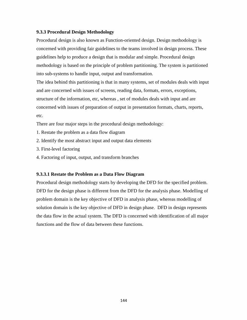
144
9.3.3 Procedural Design Methodology
Procedural design is also known as Function-oriented design. Design methodology is
concerned with providing fair guidelines to the teams involved in design process. These
guidelines help to produce a design that is modular and simple. Procedural design
methodology is based on the principle of problem partitioning. The system is partitioned
into sub-systems to handle input, output and transformation.
The idea behind this partitioning is that in many systems, set of modules deals with input
and are concerned with issues of screens, reading data, formats, errors, exceptions,
structure of the information, etc, whereas , set of modules deals with input and are
concerned with issues of preparation of output in presentation formats, charts, reports,
etc.
There are four major steps in the procedural design methodology:
1. Restate the problem as a data flow diagram
2. Identify the most abstract input and output data elements
3. First-level factoring
4. Factoring of input, output, and transform branches
9.3.3.1 Restate the Problem as a Data Flow Diagram
Procedural design methodology starts by developing the DFD for the specified problem.
DFD for the design phase is different from the DFD for the analysis phase. Modelling of
problem domain is the key objective of DFD in analysis phase, whereas modelling of
solution domain is the key objective of DFD in design phase. DFD in design represents
the data flow in the actual system. The DFD is concerned with identification of all major
functions and the flow of data between these functions.
145
Figure 9.6 Sample DFD
Source: An integrated approach to software Engineering by Pankaj Jalote, Narosa
Publication.
9.3.3.2 Identify the Most Abstract Input and Output Data Elements
Functions or transformations cannot be directly applied on physical input, and that input
is converted into a form suitable for applying transformations. Similarly, the outputs
generated by transformations are converted into physical output. This step focuses on the
separation of two type of transformations: one that performs actual transformations and
other that covert the input and output formats.
For this, you need to identify the highest abstract level of input and output. Data elements
that are farthest removed from the physical input elements and still can be used to
represent input data are called most abstract level input data elements. You can recognize
the most abstract input data elements by moving from the physical inputs toward the
outputs in the data flow diagram, until you reach the data elements that can no longer be
considered incoming.
Similarly, data elements that are farthest removed from the physical output elements and
still can be used to represent output data are called most abstract level output data
elements. You can recognize the most abstract output data elements by moving from the
physical outputs toward the inputs in the data flow diagram, until you reach the data
elements that can no longer be considered outgoing. These data elements represent the
logical output data items, and the transforms after these data items merely convert the

146
logical output into a physical output format. The actual transformation happens between
the most abstract input data elements and most abstract output data elements.
9.3.3.3 First-Level Factoring
After the identification of abstract input and output data elements, next step is to identify
the modules. In this step, a main module is specified, whose purpose is to invoke the
subordinates. For each of the most abstract input data items, an immediate subordinate
module to the main module is specified. Each of these modules is called input module,
and is responsible for delivering the most abstract data item to the main module.
Similarly, for each most abstract output data item, a subordinate output module that
accepts data from the main module is specified.
Abstract data items are used to label the respective arrows connecting these input and
output subordinate modules. Finally, for each central transform, a module subordinate to
the main one is specified. These transform modules accept data from main module and
return appropriate data back to main module.
Incoming arcs on the DFD diagram are used to specify the data items coming to a
transform module from the main module and the outgoing arcs on the DFD diagram are
used to specify the data items returned from the transform module.
Figure 9.7 First level factoring
Source: An integrated approach to software Engineering by Pankaj Jalote, Narosa
Publication.

147
9.3.3.4 Factoring the Input, Output, and Transform Branches
The first-level factoring leaves a lot of work for each subordinate module to perform.
These modules must be further factored into subordinate modules to reduce the work load
on each module at higher level. Let us start with the input modules.
Input module is concerned with producing input data. Input module can be factored as
under:
1. The transform be treated as central transform.
2. Repeat the first-level factoring process for new central transform, considering the main
module to be the input modules.
3. Create a subordinate input module for each input data stream coming into this new
central transform
4. Repeat the same process, until the physical inputs are reached.
No output subordinate modules are produced during the factoring of input modules.
Output modules can be factored by repeating the same process.
Factoring the central transform is functional decomposition. Factoring of the central
transform can be achieved by creating a subordinate transform module for each of the
transforms in this data flow diagram. This process can be repeated for the new transform
modules that are created, until we reach atomic modules.
Check your progress/ Self assessment questions- 3
Q8. What is the difference between DGD created in analysis phase and DFD created in
design phase.
________________________________________________________________________
________________________________________________________________________
________________________________________________________________________
Q9. Define most abstract level input data elements.
________________________________________________________________________
________________________________________________________________________
________________________________________________________________________

148
Q10. What is the need of factoring input, output and transformation branches?
________________________________________________________________________
________________________________________________________________________
________________________________________________________________________
9.4 Summary
Design notions are used to represent the design or design decisions during the design
phase. The structure chart is used to describe the structure of a program. Labelled
rectangular box is used to represent a module. An arrow is used to show the parent and
child relationship between the two modules. Main focus of the data design is to define the
data structure to be used by various software components. Data types and data constraints
for all data items listed in the data dictionary are specified during data design. Software
architecture may be defined as combination of software elements, their external view, and
the relationships between these components. Software architecture provides three types
of views namely, Module view, Component and connector view and Allocation view.
Procedural design methodology is based on the principle of problem partitioning. The
system is partitioned into sub-systems to handle input, output and transformation.
Modelling of solution domain is the key objective of DFD in design phase. Second step
of procedural design focuses on the separation of two type of transformations: one that
performs actual transformations and other that covert the input and output formats. Next
you need to perform the factoring of input, output and transformation modules.
9.5 Glossary
Structure chart- The structure chart is used to describe the structure of a program.
DFD- It is used to show the flow of data between various components of system.
ER Diagram- The relationship between various entities is defined in the ER diagram.
Data Dictionary- Data dictionary is used to list all data items that appear in a DFD of a
system and also to list the purpose of each data item along with the definition of all
composite data items.
SRS Document- SRS document specifies the end user requirements or the problem
domain.

149
9.6 Answers to check your progress/self assessment questions
1. Modules, interconnections.
2. The structure chart is used to describe the structure of a program. Labelled rectangular
box is used to represent a module. An arrow is used to show the parent and child
relationship between the two modules. An arrow from module A to module B, describes
that modules A is invoking module B and that module B is subordinate of module A.
3. Looping.
4. TRUE.
5. Data design is used to define the data structure to be used by various software
components. It helps to reduce the program complexity, makes the program structure
modular. The information domain model developed during analysis phase is transformed
into data structures needed for implementing the software.
6. Following are some of the advantages of software architecture:
a. Understanding and communication
b. Reuse.
c. Construction and Evolution
d. Analysis.
7. Component and connector view represents the view of the system as collection of run
time components. Objects or set of objects are run time components of class. Process is
also an example of run time component. Connectors define how the two objects interact
with each other at run time, and examples of connectors are pipes and sockets.
8. DFD for the design phase is different from the DFD for the analysis phase. Modelling
of problem domain is the key objective of DFD in analysis phase, whereas modelling of
solution domain is the key objective of DFD in design phase.
9. Data elements that are farthest removed from the physical input elements and still can
be used to represent input data are called most abstract level input data elements.
10. The first-level factoring leaves a lot of work for each subordinate module to perform.
These modules must be further factored into subordinate modules to reduce the work load
on each module at higher level.

150
9.7 References/ Suggested Readings
"1. Roger. S. Pressman, Software Engineering - A Practitioner's Approach, 7th Edition,
McGraw Hill,
2010.
2. Rajib Mall, Fundamental of Software Engineering, 3rd edition, PHI, 2009.
3. Naseeb Singh Gill, Software Engineering: Software reliability, testing and quality,
Khanna Book"
9.8 Model questions
1. Differentiate between analysis and design phase of software development life cycle.
2. Explain the procedural design methodology in detail.
3. Explain the architectural design methodology in detail.
4. What is the need of data design?
5. Explain structure chart. Also give an example.

151
Lesson- 10 Object oriented concepts
Structure of the lesson
10.0 Objective
10.1 Introduction
10.2 Object oriented concepts
10.3 Unified Modelling Language (UML)
10.4 OO Design Methodology
10.5 Summary
10.6 Glossary
10.7 Answers to check your progress/self assessment questions
10.8 References/ Suggested Readings
10.9 Model questions
10.0 Objective
After studying this lesson, students will be able to:
1. Define various terms associated with object oriented programming.
2. Explain the use of UML in object oriented design.
3. Discuss various types of diagrams created in UML.
4. List various steps involved in OO design methodology
10.1 Introduction
Object-oriented (OO) approach is the most popular software development approach
today. An object oriented design is less affected by change in requirements. Inheritance
and close association of objects in design to problem domain encourages the reusability
of modules that help to reduce the overall cost and effort needed to develop the software.
Object-oriented approach provides structural support for implementing abstraction.
10.2 Object oriented concepts
Class- A class in object oriented design forms the basis for any OOP language. A class is
a collection or binding of data members and member functions. All other objectives of
object oriented programming can be achieved only with the help of class type and you

152
cannot call any program or language supporting OOP paradigm if it does not include
class data type.
Object- A class is simply a type that forms the basis for OOP. An object may be defined
as instance of a class. It is the active entity of a class. Object occupies space in the
memory. When you create multiple objects of a class; multiple instances class members
is created.
There was a clear separation between the data and functions in procedural or structural
languages. More emphasis was given to the coding than data. A class supports the
encapsulation feature of OOP. Encapsulation means binding of data and functions
(coding) in a single type. A class is a collection of data members and member functions,
and hence it supports encapsulation. Encapsulation leads to data hiding.
Objects are entities that encapsulate some state and provide services to be used by its
environment. The basic property of an object is encapsulation. Interface of an object
refers to the services that can be requested from the object. Encapsulation allows only
limited access to the data, that lets you achieve data integrity. State of an object is
preserved until the object is destroyed. Attributes and services provided by an object are
defined by the class, it belongs to. A class may also be considered as a set of objects that
share same behaviour.
A system consists of a number of objects belonging to different classes. These objects
interact with each other in order to achieve the system objective. Mechanism of
messaging is used for interaction between the objects. The object that receives the request
executes the appropriate service requested and returns the result to the object requesting
for the service. It is a clear case of encapsulation and abstraction supported by objects.
Abstraction in OOP means providing only the interface to the users and hiding the un-
necessary details or coding from the user. Abstraction is also a process of creating some
abstract object from a class that depicts a real life entity. Some of the examples of
abstract objects are employee, student, car, account, human, etc. The main objective of

153
abstraction is to reduce the complexity and improve the performance. A class that
contains only the prototype of data members and member functions is a perfect example
of abstract view of class. You can access member function of class using objects of that
class without knowing any details about that member function.
Relation between object- Two objects are related in some way, if an object invokes a
service in other object, and there is an association between the two objects, if an object
uses a specified service of another object. Links are used to represent such association
between objects. Association leads to visibility. Suppose that object A wants to send a
message to object B, or invoke some service of object B, then the object B must be
visible to object A in the final program definition.
Another important type of relationship between objects is aggregation. It is used to
represent the whole/part-of relationship. Aggregation is often referred to as containment.
For example, if an object OBJ1 is an aggregation of objects OBJ2 and OBJ3, aggregation
states that objects OBJ2 and OBJ3 will normally be within object OBJ1.
Inheritance- It is probably the most powerful feature of object oriented programming. It
lets you create a new class by re-using or inheriting the features of already existing class
and adding new features to the same. Inheritance helps you to improve the reusability of
your code by re-using already tested classes. It helps to reduce a lot of programming
effort and also improves the performance. Inheritance also helps you to break one large
class into smaller classes that helps improve the abstraction.
Inheritance represents “is a” relation. Inheritance relation can be best represented using
hierarchical structure. A subclass inherits the features of a superclass. Hierarchy should
be such that an object of a class is also an object of all its superclasses in the problem
domain. Subclass is an extension of superclass , or all common features of the subclasses
are accumulated in the superclass. Features can be inherited from the superclass class and
used in the subclass directly. A derived class can also be considered to be a specialized

154
class of available abstract classes. In case of strict inheritance, a subclass takes all the
features from the superclass and adds additional features to specialize it.
In strict inheritance, all data members and operations of base class are available in the
derived class.
In case of non-strict inheritance, subclass does not inherit all the features of superclass, or
redefines some of the features of superclass.
A class may also inherit from multiple classes. It means that the relationship may not
necessarily be a tree like hierarchical structure. When a subclass inherits features from
multiple classes, it is called multiple inheritance.
Polymorphism- In yet another key feature of OOP, you can create multiple forms of a
single object. Polymorphism is also known as overloading. Polymorphism is un-
avoidable in a system that supports inheritance, as there “is a” relation supported by
inheritance. If B is a subclass of superclass A, an object of class B can also be used to
access the instance of class A. Static type of object polymorphism is specified in the
program text, and it remains unchanged. The dynamic type of object polymorphism can
change from time to time and is known only at reference time. The dynamic type of
object will be defined at the time of reference of the object. This type of polymorphism
requires dynamic binding of operations. Dynamic binding means that the code associated
with a given procedure call is not known until the moment of the call.
Check your progress/ Self assessment questions- 1
Q1. Define class and object.
________________________________________________________________________
________________________________________________________________________
________________________________________________________________________
Q2 Define abstraction.
________________________________________________________________________
________________________________________________________________________

155
________________________________________________________________________
Q3. Define inheritance.
________________________________________________________________________
________________________________________________________________________
________________________________________________________________________
10.3 Unified Modelling Language (UML)
UML is a graphical tool for representing object-oriented design. It is called modelling, as
it tries to define the relationship and interaction between the classes in the system
Class Diagram- It is the core of the UML model. A class diagram is used to define the
following:
1. Classes that are part of the system.
2. Association or relationship between the classes.
3. Inheritance relationship between the classes.
A class in UML is represented as a box divided into three parts. Top part specifies the
class name, middle part lists the data members of attributes of the class and the bottom
part specifies the functions that transform the class state.
Figure 10.1: Simple representation of class
It is important to describe the relationships between the classes, as the interaction
between the classes is must to achieve the system objective. One common relationship is
the generalization-specialization relationship between classes. It can be best represented
using inheritance hierarchy in which, properties of general significance are assigned to a
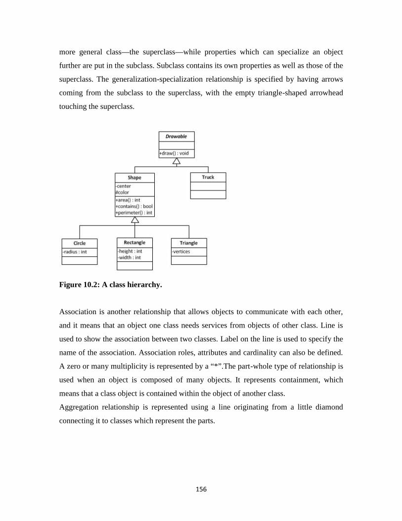
156
more general class—the superclass—while properties which can specialize an object
further are put in the subclass. Subclass contains its own properties as well as those of the
superclass. The generalization-specialization relationship is specified by having arrows
coming from the subclass to the superclass, with the empty triangle-shaped arrowhead
touching the superclass.
Figure 10.2: A class hierarchy.
Association is another relationship that allows objects to communicate with each other,
and it means that an object one class needs services from objects of other class. Line is
used to show the association between two classes. Label on the line is used to specify the
name of the association. Association roles, attributes and cardinality can also be defined.
A zero or many multiplicity is represented by a “*”.The part-whole type of relationship is
used when an object is composed of many objects. It represents containment, which
means that a class object is contained within the object of another class.
Aggregation relationship is represented using a line originating from a little diamond
connecting it to classes which represent the parts.

157
Figure 10.3: Aggregation and association.
Sequence and Collaboration Diagrams
Class diagrams do not represent the dynamic behaviour of the system. Sequence
diagrams or
collaboration diagrams are used to represent the system behaviour when it performs some
of its functions. Sequence diagrams and collaboration diagrams are collectively known as
interaction diagrams.
A sequence diagram shows the temporal ordering and series of messages exchanged
between objects as they collaborate or interact to implement desired system functionality.
Objects, instead of classes participate in the sequence diagrams, as it tries to depict the
dynamic behaviour of the system. Objects in sequence diagram are shown on top with the
help of labelled boxes. Lifeline of an object is represented using a vertical bar. Arrow is
used to represent message from one object to another from the lifeline of one to the
lifeline of the other. Message name generally refers to a method in the class. Each
message has a return, which is when the operation finishes and returns to the invoking
object. It is desirable to show the return message explicitly, even though it is not
mandatory to. This is done by using a dashed arrow.
Figure 10.4: Sequence diagram

158
A collaboration diagram is also a good representative of objects communication and
looks more like a state diagram. An object is represented as box, and messages are shown
as numbered arrows between the objects. Message numbering is used to capture the
chronological ordering of messages.
Figure 10.5: Collaboration diagram.
Activity Diagram. It is also used for modelling the dynamic behaviour of the system.
It focuses on modelling the activities during the system execution. An activity in activity
diagram is represented using oval shape. The activity name is written inside the oval
shape. System proceeds between activities and which will be the next activity depends on
some decision. Diamond shape is used to represent the decision and the same is
connected to multiple activities. Activity diagram resembles somewhat to flow charts. An
activity diagram also have notation to specify parallel execution of activities in a system.

159
Figure 10.6 Activity Diagram
Check your progress/ Self assessment questions- 2
Q4. What is the role of class diagram?
________________________________________________________________________
________________________________________________________________________
________________________________________________________________________
Q5. How are objects represented in sequential diagram?
________________________________________________________________________
________________________________________________________________________
________________________________________________________________________
Q6. Explain activity diagram.
________________________________________________________________________
________________________________________________________________________
________________________________________________________________________

160
10.4 OO Design Methodology
Object oriented design is a specification of classes and objects that are part of the system
implementation. It is very close to the real code and implementation phase should require
you to add only details about methods or attributes to the design. An object oriented
design generally consists of the following steps:
– Identification of classes and the relationships between them.
– Design of dynamic model and the definition functions on classes.
– Design of functional model and the definition of functions on classes.
– Identification of internal classes and functions.
– Optimization and packaging.
Identification of classes and their relationships requires :
1. Identification of object types in the problem domain.
2. Aggregation and association between classes.
3. Identification of class attributes, and
4. Services that each class will provide to the system.
It is basically concerned with the design of the initial class design
Design of dynamic model and the definition functions on classes
The initial class diagram only gives the module-level design. This design needs further
modelling to ensure that the expected behaviour for the events can be supported. Main
aim of this step, is to specify how the state of various objects changes when events occur.
An event occurs, when a request is made to an object for some service. A series of events
during system execution refers to a scenario.
A scenario defines the different services being performed by each object. . All scenarios
put together, represent the behaviour of complete system. A design capable of supporting
all the scenarios, is also capable of supporting the desired dynamic behaviour of the
system.
Functional Modelling

161
It does not consider the control aspects of the computation, and is only concerned with
how the output
values are computed from the input values of the system. Functional view represents the
mapping from inputs to outputs and also the steps involved in achieving this mapping.
DFD is used to represent the functional modelling. Functional modelling is done to
ensure that the object model can perform the transformations required from the system.
Defining Internal Classes and Operations
It is important to consider the implementation issues before the final design of the
system. Each class is evaluated to see if it is fit in its current form to be included in the
final design. Some of the classes may even be removed from the design. Then the
implementation of methods on the classes is considered.
Once the designer is satisfied with the implementation of each class and its methods, the
system design is complete.
Optimizing and Packaging
The last step is concerned with the issue of efficiency. Focus is to ensure that the final
structures should not deviate too much from the logical structure. Various optimizations
are possible, and much is left to the experience and judgement of a designer.
Check your progress/ Self assessment questions- 3
Q7. Define scenario.
________________________________________________________________________
________________________________________________________________________
________________________________________________________________________
Q8. Define functional modelling.
________________________________________________________________________
________________________________________________________________________
________________________________________________________________________

162
10.5 Summary
A class is as a collection or binding of data members and member functions. An object
may be defined as instance of a class. It is the active entity of a class. Mechanism of
messaging is used for interaction between the objects. Abstraction in OOP means
providing only the interface to the users and hiding the un-necessary details or coding
from the user. If an object invokes a service in other object, and there is an association
between the two objects. Association leads to visibility. Suppose that object A wants to
send a message to object B, or invoke some service of object B, then the object B must be
visible to object A. Inheritance lets you create a new class by re-using or inheriting the
features of already existing class and adding new features to the same. Polymorphism is
also known as overloading, and it lets you create multiple forms of a single object.
Polymorphism is un-avoidable in a system that supports inheritance. Class Diagram is
used to represent classes, association and relationship between classes. Sequence
diagrams or collaboration diagrams are used to represent the system behaviour when it
performs some of its functions. Activity Diagram is also used for modelling the dynamic
behaviour of the system. It focuses on modelling the activities during the system
execution. An object oriented design generally consists of the following steps:
– Identification of classes and the relationships between them.
– Design of dynamic model and the definition functions on classes.
– Design of functional model and the definition of functions on classes.
– Identification of internal classes and functions.
– Optimization and packaging.
10.6 Glossary
Class- A class is as a collection or binding of data members and member functions.
Object- An object may be defined as instance of a class. It is the active entity of a class.
Abstraction- Abstraction in OO design means providing only the interface to the users
and hiding the un-necessary details or coding from the user.
Inheritance- It lets you create a new class by re-using or inheriting the features of already
existing class and adding new features to the same.
Polymorphism- It lets you create multiple forms of a single object.

163
Class Diagram- It is used to represent classes, association and relationship between
classes.
Sequence diagram- It is used to represent the system behaviour when it performs some of
its functions.
Activity Diagram- It is also used for modelling the dynamic behaviour of the system.
10.7 Answers to check your progress/self assessment questions
1. A class is as a collection or binding of data members and member functions. An object
may be defined as instance of a class. It is the active entity of a class. Object occupies
space in the memory.
2. Abstraction in OOP means providing only the interface to the users and hiding the un-
necessary details or coding from the user. Abstraction is also a process of creating some
abstract object from a class that depicts a real life entity.
3. Testing lets you create a new class by re-using or inheriting the features of already
existing class and adding new features to the same. Inheritance helps you to improve the
reusability of your code by re-using already tested classes.
4. A class diagram is used to define the following:
a. Classes that are part of the system.
b. Association or relationship between the classes.
c. Inheritance relationship between the classes.
5. Objects in sequence diagram are shown on top with the help of labelled boxes. Lifeline
of an object is represented using a vertical bar. Arrow is used to represent message from
one object to another.
6. Activity Diagram is used for modelling the dynamic behaviour of the system. It
focuses on modelling the activities during the system execution. System proceeds
between activities and which will be the next activity depends on some decision.
7. A series of events during system execution refers to a scenario.
A scenario defines the different services being performed by each object. . All scenarios
put together, represent the behaviour of complete system.
8. Functional modelling does not consider the control aspects of the computation, and is
only concerned with how the output values are computed from the input values of the
164
system. Functional view represents the mapping from inputs to outputs and also the steps
involved in achieving this mapping.
10.8 References/ Suggested Readings
"1. Roger. S. Pressman, Software Engineering - A Practitioner's Approach, 7th Edition,
McGraw Hill,
2010.
2. Rajib Mall, Fundamental of Software Engineering, 3rd edition, PHI, 2009.
3. Naseeb Singh Gill,Software Engineering: Software reliability, testing and quality,
Khanna Book
Publishing, 2011."
10.9 Model questions
1. Explain activity diagram with the help of an example.
2. Explain various steps involved in OO design methodology.
3. Explain sequence diagram with the help of an example.
4. Define class, object, inheritance, abstraction and polymorphism.
5. Explain class diagram with the help of an example.
165
Lesson- 11 Software Testing
Structure of the lesson
11.0 Objective
11.1 Introduction
11.2 Software testing
11.3 A software testing cycle
11.4 Objectives of software testing
11.5 Principles of software testing
11.6 Testability
11.7 Black-Box Testing
11.8 White-Box Testing
11.9 Validation Testing
11.10 Types of Validation Testing
11.10.1 Unit Testing
11.10.2 Integration Testing
11.10.3 System Testing
11.10.4 Acceptance Testing
11.11 Summary
11.12 Glossary
11.13 Answers to check your progress/self assessment questions
11.14 References/ Suggested Readings
11.15 Model questions
11.0 Objective
After studying this lesson, students will be able to:
1. Define the term software testing.
2. List key objectives of software testing.
3. Explain key principles of software testing.
4. Explain the concept of testability.
5. Discuss in detail various types of software testing techniques.

166
11.1 Introduction
No matter what product you produce, it is imperative to test the product before it is
handed over to the customer. Software testing is a key phase in development process of
any software. Software must be tested to determine if it meets the standards and
requirements defined in the SRS. Depending on the nature of the software under
development, testing can be performed by the developer itself, or by a special team
comprising of testers. Testing can be performed right from the beginning of the software
development process or at the end, before the software is handed over to the customer. In
this lesson you will also learn about various software testing techniques practically used.
11.2 Software testing
Testing refers to the process of evaluating a system or to check if it satisfies the specified
requirements or not. Testing is performed by executing the system to identify errors, or
gaps in the requirements and actual product. Software testing is an automated process.
Software testing refers to design of a special type of software that is used to find bugs or
gaps in some other software system.
Testing is the fourth phase in waterfall model. But the same can be started in parallel to
first three phases to identify errors in the very beginning, It helps to reduce the time and
cost to correct these errors. It depends on the model in use. For example, in case of
incremental waterfall model, testing can be performed after each iteration or phase.
Testing in requirement gathering phase is done to analyse and verify the requirements.
Reviewing of the design in design phase to improve the same is also a type of testing.
Parallel review can also be performed by the developers during the implementation.
Testing process mainly includes:
Execution of the software using the inputs that satisfies the operational conditions.
Verifying or comparing the gaps between the actual and the desired outputs.
Verifying or comparing the resultant and expected states.
Measuring various performance metrics such as amount of memory consumed,
time taken to execute, resources used, etc.

167
Key terminologies used in software testing
Error- When the resultant state is incorrect or not same as expected state.
Failure- Failing to provide the expected service to the user.
Bug- Missing or incorrect code that may lead to a failure.
Test case- It refers to a set of inputs, operational conditions, and expected outcome.
Test Suite- It refers to a set or collection of interrelated test cases with the aim of
common testing goal.
Test Driver- Software tool that is responsible for the application of test cases.
Test strategy- It refers to an algorithm used to select test cases from a representation.
11.3 A software testing cycle
Figure 11.1 Software testing cycle
The process starts by designing the test cases or picking up already designed test cases.
Then the test data or input is prepared. The actual software to be tested is then executed
on the test data and the results are obtained. Results specify the identified errors, bugs,
gaps, and also the value for various measures such as memory used, time taken to
successful completion, etc. The results are then compared with the test cases to identify
the gaps and generate the test report.
11.4 Objectives of software testing
Following are the key objectives of software testing:
1. Finding errors or bugs that a developer might have unintentionally left in the source
code of various software modules.
2. Providing information about the level of software quality.
3. To make sure that the end result meets the business and user requirements.

168
4. To ensure that the software is reliable to be deployed in real work scenario.
5. Software testing shall evaluate the capabilities of a system to show that a system
performs as intended.
6. Software testing shall also verify documents created throughout software development
life cycle.
Check your progress/ Self assessment questions- 1
Q1. Define software testing.
________________________________________________________________________
________________________________________________________________________
________________________________________________________________________
Q2 What is the advantage of starting with the software testing from the very beginning of
development process?
________________________________________________________________________
________________________________________________________________________
________________________________________________________________________
Q3. _______________ refers to a set of inputs, operational conditions, and expected
outcome, and ____________________ refers to a set or collection of interrelated test
cases with the aim of common testing goal.
11.5 Principles of software testing
Following are the seven key principles of software testing
1. Testing shows the presence of bugs- Objective of testing is to find bugs and not declare
a software as bugs free. Hence, a key principle of software testing is to find as many bugs
as possible.
2. Exhaustive testing in impossible- It is not possible to test all possible combinations of
data and scenarios for a large software system. Levels of risks and priorities are used to
focus on most important aspects to test.

169
3. Early testing- Sooner you start, better and easy it is. The testing process must start with
the very first phase of the development cycle. It makes the cost to fixing the errors
minimal and also reduces the time to fix them.
4. Defect clustering- Pareto Principle to software testing states that: approximately 80%
of the problems are found in 20% of the modules.
5. The pesticide paradox- If you keep running the same set of tests over and over again,
chances are no more new defects will be discovered by those test cases. Regression
testing must be used after the bugs are fixed, to make sure the new changed software has
not broken any other part of the software.
6. Testing is context dependent- Different methodologies, techniques and types of testing
is related to the type and nature of the application.
7. Absence of errors fallacy- If the testing fails to find any bugs in the software, it doesn’t
mean that the software is ready to be delivered. It may be possible that the tests were
designed to see if the software matched the user’s requirements?
11.6 Testability
Testability is a software quality characteristic. Some of the definitions of testability:
"The degree to which a software or its modules facilitates testing is called testability."
or
"Testability is the degree of difficulty of testing a system".
Testability is determined by both the system being tested and its development approach.
Higher testability means better tests at same cost and lower testability means fewer
weaker tests at same cost. Testability determines the limit to which the risk of costly bugs
can be reduced to an acceptable level. Delivering a system with nasty bugs, means poor
testability. Improved testability means there are good chances to find bugs as you do
more testing. Designing a software system with testing in mind is called design for
testability.

170
Following are some of the characteristics of testability, which are listed below:
1. High quality software can be tested in a better manner. This is because if the
software is designed and implemented considering quality, then comparatively fewer
errors will be detected during the execution of tests.
2. Software becomes stable when changes made to the software are controlled and
when the existing tests can still be performed.
3. Testers can easily identify whether the output generated for certain input is
accurate simply by observing it.
4. Software that is easy to understand can be tested in an efficient manner. Software
can be properly understood by gathering maximum information about it. For example, to
have a proper knowledge of the software, its documentation can be used, which provides
complete information about the software code, thereby increasing its clarity and making
the testing easier.
5. By breaking software into independent modules, problems can be easily isolated
and the modules can be easily tested.
11.7 Black-Box Testing
In case of Black-Box testing, the software is treated as a black box and the testing is
performed without having any knowledge of the components or modules of the software.
Tester doesn't have knowledge of the software architecture and cannot view the source
code. Black box testing is performed from the user interface. The tester provides inputs
using the user interface and checks the output without knowing the processing details.
Figure 11.2 Black-Box testing
Advantages of Black-Box testing
1. It is perfect for testing large software's.
2. It is suited when there is less time in delivery to the customer and the delivery is
incremental.

171
3. Access to the code is not required in this method, it provides full abstraction.
4. No need of highly skilled testers, even moderately skilled testers, who have no
knowledge of the software can be used to test the software.
5. Testing from user interface is easy, it is just like operating the software.
Disadvantages of Black-Box testing
1. Only a limited scenario can be tested from the user interface.
2. It is not the most efficient method of testing, as the tester has knowledge of the
software modules.
3. There is no difference between the highly skilled and moderately skilled testers, as the
tester cannot target any module that is prone to errors.
4. It is difficult to design the test cases.
11.8 White-Box Testing
White-box testing methodology refers to the detailed investigation of structure and of the
software modules and code. White-box testing is also known as glass or open-box testing,
as everything is visible from outside to the tester. Only the skilled testers are used to
perform white-box testing on a software, as they need to have complete knowledge of the
software architecture and design. The tester digs deep into the source code to find out
which sections of the code that might be coded inappropriately.
Figure 11.3 White-Box testing
Advantages of White-Box Testing.
1. It is easy for the skilled tester to identify the type of data that can help in testing the
application effectively.
2. It can help in optimizing the code.
3. Tester can even help in removing the ineffective code segments.

172
4. Maximum coverage is achieved during test, due to the knowledge levels of skilled
tester.
Disadvantages of White-Box Testing.
1. It is more costly method of testing in terms of both time taken and the cost to hire the
skilled testers.
2. It is not possible to cover each and every segment of the code to find out hidden errors.
3. Specialized tools like code analyzers and debugging tools are needed to perform
White-Box testing.
4. It suffers from the biasness of the skilled tester, as it may ignore certain code segments
and focus only on a few code segments.
Check your progress/ Self assessment questions- 2
Q4. Define testability.
________________________________________________________________________
________________________________________________________________________
________________________________________________________________________
Q5. Explain black-box testing.
________________________________________________________________________
________________________________________________________________________
________________________________________________________________________
Q6. List two advantages of white-box testing.
________________________________________________________________________
________________________________________________________________________
________________________________________________________________________

173
11.9 Validation Testing
Validation Testing is performed to check whether the software satisfies the customer
needs or not. Validation testing is done during the software development process and also
at the end of it.
Validation testing is carried out before the software is handed over to the customer. The
aim of validation testing is to ensure that the software is made according to the customer
requirements. The acceptance of the software by the end customer is part of validation
testing.
Validation Testing Process
Bugs or errors found during the testing process are logged for the development team to
fix. them. Once the bugs are fixed by the developers, testing process is repeated to ensure
that the bugs have been fixed, and no new bugs are introduced due to changes made by
the developers.
Validation testing can be described as follows:
Validation Planning
Define Requirements
Select Appropriate Team
Develop Documents
Evaluation
Incorporating Changes
The Basic Tests
The validation testing process can be best viewed as V-Model as shown in the figure
below:

174
Figure 11.4 V-Model of validation testing
11.10 Types of Validation Testing
Normally the testers are involved right from the very beginning of the development
process and the testing starts immediately after a module of the system has been
developed. A part from the basic tests, the different types of software validation tests are:
11.10.1 Unit Testing
Unit testing is also known as Component testing. Unit testing is performed by the
developers on the individual units of source code. The aim of the tests carried out in this
testing type is to search for defects in the software component. At the same time, it also
verifies the functioning of the different software components, like modules, objects,
classes, etc.
It is performed before the setup is handed over to the testing team to execute the test
cases. Test data used by developers for unit testing is different from the test data used by
quality assurance team. The goal of unit testing is to show that individual parts of a
program are correct in terms of requirements and functionality.
Limitations of Unit Testing
A developer cannot find each and every bug in the program, as there is a limit to the
number of test data and scenarios that a developer can use to verify a source code. Once
all options or scenarios in the mind of the developer have exhausted, the unit code is
integrated with the other units.

175
11.10.2 Integration Testing
This is an important part of the software validation model, where the interaction between
the different interfaces of the components is tested. Integration testing is done to check
the functional correctness of the units when executed after integration. Integration testing
can be done using two approaches:
1. Bottom-up integration testing
It starts by testing the units in isolation, followed by tests of progressively higher-level
combinations of units called modules or builds.
2. Top-down integration
In this testing, the highest-level modules are tested first , followed by testing the lower-
level modules.
A more comprehensive software testing performs bottom-up testing , followed by top-
down testing. Multiple tests of the complete application are performed in a scenario that
is simulation of actual situations.
11.10.3 System Testing
System testing is performed on the whole system or complete software. The concern of
this testing is to check the behaviour of the whole system as defined by the scope of the
project. Once all the modules are integrated, the software as a whole is tested rigorously
to see that it meets the specified requirements and standards. Specialized testing teams
are used to conduct the system testing. While carrying out the tests, the tester is not
concerned with the internals of the system, but checks if the system behaves as per
expectations.
Following are the key benefits of system testing:
1. It is that phase of the SDLC, where it is judged whether the software as a whole is up
to the standards and meets the minimum requirements.
2. The software is tested thoroughly to verify that it meets the functional and technical
specifications.

176
3. The software is tested in an environment that is very close to the actual environment
where it will be eventually deployed.
4. System testing enables us to test, verify, and validate both the business requirements as
well as the software architecture.
11.10.4 Acceptance Testing
A tester has to think like the client, or even interact with the client and test the software
with respect to user needs, requirements, and business processes, and determine whether
the software is ready for the delivery or not. This testing is key to determine the
confidence of the client in the system.
Check your progress/ Self assessment questions- 3
Q. Top-down integration starts by testing the units in isolation, followed by tests of
progressively higher-level combinations of units called modules or builds. ( TRUE /
FALSE )
Q8. __________ testing comes before the user acceptance testing.
________________________________________________________________________
________________________________________________________________________
________________________________________________________________________
11.11 Summary
Testing refers to the process of evaluating a system or its to check if it satisfies the
specified requirements or not. Following are 7 key principles of testing:
The degree to which a software or its modules facilitates testing is called testability.
Testability determines the limit to which the risk of costly bugs can be reduced to an
acceptable level. Delivering a system with nasty bugs, means poor testability. In case of
Black-Box testing, the software is treated as a black box and the testing is performed
without having any knowledge of the components or modules of the software. White-box
testing methodology refers to the detailed investigation of structure and of the software
modules and code. Validation testing is done during the software development process

177
and also at the end of it. Validation testing is carried out before the software is handed
over to the customer. Unit testing is performed by the developers on the individual units
of source code. Integration testing is done to check the functional correctness of the units
when executed after integration. System testing is performed on the complete software to
check the behaviour of the whole system as defined by the scope of the project.
Acceptance testing is done to test the software with respect to user needs, requirements,
and business processes, and determine whether the software is ready for the delivery or
not.
11.12 Glossary
Test case- It refers to a set of inputs, operational conditions, and expected outcome.
Test Suite- It refers to a set or collection of interrelated test cases with the aim of
common testing goal.
Software testing- It refers to the process of evaluating a system or to check if it satisfies
the specified requirements or not.
Bug- Missing or incorrect code that may lead to a failure.
Testability- Degree to which a software or its modules facilitates testing is called
testability.
11.13 Answers to check your progress/self assessment questions
1. Software testing refers to the process of evaluating a system or its to check if it
satisfies the specified requirements or not. Testing is performed by executing the system
to identify errors, or gaps in the requirements and actual product. Software testing refers
to design of a special type of software that is used to find bugs or gaps in some other
software system.
2. Starting with the software testing from the very beginning of development process
helps to reduce the time and cost to correct these errors.
3. Test case , test suite.
4. The degree to which a software or its modules facilitates testing is called testability, or
testability is the degree of difficulty of testing a system.
178
5. In case of Black-Box testing, the software is treated as a black box and the testing is
performed without having any knowledge of the components or modules of the software.
Tester doesn't have knowledge of the software architecture and cannot view the source
code.
6. Advantages of White-Box Testing:
a. It is easy for the skilled tester to identify the type of data that can help in testing
the application effectively.
b. Maximum coverage is achieved during test, due to the knowledge levels of skilled
tester.
7. FALSE.
8. System.
11.14 References/ Suggested Readings
"1. Roger. S. Pressman, Software Engineering - A Practitioner's Approach, 7th Edition,
McGraw Hill,
2010.
2. Rajib Mall, Fundamental of Software Engineering, 3rd edition, PHI, 2009.
3. Naseeb Singh Gill,Software Engineering: Software reliability, testing and quality,
Khanna Book
Publishing, 2011."
11.15 Model questions
1. Differentiate between black-box and white-box testing.
2. What is validation testing? Explain various tests performed in validation testing.
3. List various principles of software testing.
4. Define testability.
5. What is software testing? What is the need of it?

179
Lesson 12: Verification and Validation
12.0 Objective12.1 Introduction12.2 Verification12.3 Validation12.4 Need of Verification and Validation12.5 Foremost of verification and validation12.6 Software verification and validation approaches and their applicability12.7 Principal of Verification and Validation12.8 Difference between Verification and Validation12.9 Verification activities12.10 Validation activities12.11 System View12.12 Difficulty in Verification and Validation12.13 Verification and Validation in life cycle
12.13.1 Verification and Validation in Requirement phase12.13.2 Verification and Validation in Design phase12.13.3 Verification and Validation in Implementation phase12.13.4 Verification and Validation in Integration phase12.13.5 Verification and Validation in Testing phase12.13.6 Verification and Validation in Maintenance phase
12.14 Example12.15 Summary12.16 Glossary12.17 Answers to self-answering questions12.18 References / Suggested readings12.19 Model questions / Self answering questions
12.0 Objective
This chapter aims at understanding the major and most important part of softwareengineering which is verification and validation because unless until one does not knowhow to verify and validate a software product that software product is of no use whichdoesn’t meet the user’s business requirements. In this chapter we will learn basics ofmaking a quality software product which will leads to better performance and a flawlessproduct.
12.1 Introduction
In software Engineering verification and validation are two very wisely used terms whichseems to be same but the fact is that the both of these terms are quite different.
Two points must be considered about verification and validation
Fulfils the SRS document’s requirements

180
Fulfils the user’s requirements
When we talk about the SRS document’s requirements, we know that SRS is completelyaccepted by both consumer and producer, so once it fulfils the SRS requirements the finalproduct produced will be quality oriented.
We will talk about both of these terms in detail but firstly let’s talk about these terms oneby one and try to understand these terms.
12.2 Verification
Verification in simple words means that we will check the product/software inintermediate phases of SDLC to make sure that whether we are building the product onright track or not?
Verification falls under two categories
The right method The right product
By right method we mean that what so ever we have already planned to make thatproduct/software. Are we following that way so that the final product which will be madewill be correct and by right product we mean that final software which will be handedover to the end user will perform according to user’s requirements &fulfils his/herobjectives.
12.3 Validation
Validation is a method of evaluating the end product/software which we are going tohanded over to the user will match the user’s business requirements.
We can understand this by taking a simple example that if we are an owner of arestaurant and we have hired a software company to automate the daily operations of ourrestaurant, so as an owner or an employee of a restaurant we have nothing to do with theintermediate steps of software building. We will check the final product by printing or byfiring various commands and by testing it by any means to ensure that is the finalproduct/software meeting our restaurant’s business requirements or not?
And if not I will refuse to accept the product. This will be the real validation & completetesting.

181
12.4 Need for verification and validation
Gaining early intuition in software performance Synchronizing design and test data Managing the testing procedure
Improved software quality Reduced assurance cost
Reduced prototyping cost Flattened design cycle time
Fig 12.1
Understanding need of verification and validation
12.5 Foremost of verification and validation
Here we have some questions that should be answered before we start going in moredetails of verification and validation.
Validation
“Are we working on the right system?” Does our software product precisely capture the actual problem? Does our product have justification for the needs of all the participants?
Verification
“Are we working on the right system?” Does our software product meet the customer’s specifications?

182
Are we implementing the product correctly? Does the given system work according to user’s instructions?
12.6 Software verification and validation approaches and their applicability
Verification and validation of the software product is being carried out throughout thedevelopment of the product. There are a lot of techniques to check software either withisolation or combing of modules. In a broad way we have classified these approaches infive broad ways which are discussed in next section
1. Software Technical ReviewsThis approach includes techniques like walk-throughs, audits and inspections.Software technical reviews can be used to examine all the software productsespecially applicable for natural language software.
2. Software TestingSoftware testing is a process of testing that the software we are working upon isup to the mark or not i.e. the software meets the user’s requirements or not.There are mainly three main types of testing
a. Alpha Testing. Alpha testing refers to the software testing carried outby the test team with in the developing environment.
b. Beta testing. Beta testing is the software testing performed by theselected group of friendly customers.
c. Acceptance testing. This testing is performed by the customer todetermine whether to accept the software product or to reject it.
183
Levels of testing
Module testingIntegration testingSystem testingRegression testing
3. Proof of correctnessProof of correctness is mathematical & an analytical technique which providesproofs of getting work done correctly for example some facts and figures can helpto get correct results about any software product. For example any restaurantautomation software will provide correct bills and takes correct inputs are said tobe proof of correctness.
4. Simulation and prototypingSimulation is a technique of model building, which helps to understand thesoftware product in more clarification. There are many approaches to understandthe needs and working of software but simulating the software is the best way.In simulation we make a dummy model of that software and test it according toour requirements and with random set of inputs.
5. Requirement tracingTracing user’s requirements because it may vary as time passes away. There are alot of situations where user ask developers to make changes in the softwareproduct according to their convenience so in that case it is always important totrace user’s requirements and specifications.
Self-Assessment Questions
Exercise-I
1. What is acceptance testing?2. What is agile testing?3. What is application programming interface?4. What are primary things for verification and validation?
12.7 Principle of verification and validation
The process of reviewing, inspecting, testing, checking, auditing or establishing &documenting items, services & processes conforms to specified requirements.
The act of evaluating the system & components, checking whether the softwareproduct result of given development phase satisfy the requirements introduced at the startof the phase.

184
According to IEEE/ANSI definition. “It is the process of evaluating a system orcomponents during or at the end of the development process to determine whether itsatisfies the specified requirement”. Validation is therefore ‘end to end’ verification[IEEE Education society].
12.8 Difference between Verification and Validation
Up to now we get to know what are verification and validations. So let’s now try tounderstand the difference between these two terms
Criteria Verification ValidationDefinition Verification is the process of
evaluating the product inintermediate stages to check whetherall the phases of SDLC are up to themark or not.
Validation is the checking of finalproduct before giving it to the end user.
Requirements It checks that whether the product ismade as per specified requirementsand design specifications
It checks whether the product is made asper user’s business requirements or not.
Right Product It checks “ Are we on right track inprogress of making the product”
It checks “Have we made the rightproduct?”
Execution It is checked without executing theproduct
It is checked with executing the product.
Testing It includes all the static testingtechniques.
It involves all the dynamic testingtechniques.
Examples Examples of verification includesreviews, inspection and walkthrough
Examples of validation includes alltypes of testing like smoke, regression,functional, systems and UAT
12.9 Verification activities includes Technical reviews, software inspection and walkthroughs
Verifying that whether the software requirements meet the user’s requirements. Unit testing so that each unit performs as per specified.
Integration testing i.e. combining two or more units results to good / satisfiedperformance.
System testing i.e. compilation of the complete system / software to check itsperformance.
Acceptance testing whether the end user accept the product or not. Audit

185
The process of verification can be explained diagrammatically as below.
Fig 12.2 Verification Activities
[Source: http://rene-vyv-software.blogspot.in/2012_08_01_archive.html]
Self-Assessment Questions
Exercise -II
1. What is black box testing?2. What is CMM?3. What is code walkthroughs?

186
12.10 Validation activities includes Assuring that the product meets user’s business requirements Data checksum’s Hardware testing Critical system testing
Software product meets user’s requirements Random Testing
Deficiency in software product is being checked by end user Outputs are analyzed
12.11 System view in terms of verification and validation
Fig 12.3
System view of verification and validation

187
12.12 Difficulty & Importance of verification and validation
Fig 12.4
Difficulty in verification and validation
Fig 12.5
Process of verification validation with credibility

188
Self-Assessment Questions
Exercise –III
1. What is quality assurance?2. What is software requirement specification?3. What is stress testing?
12.13 Verification and validation in life cycle.
12.13.1 Verification and Validation of Requirement Phase
Verification and Validation in requirement phase focuses on acquiringinformation about software or product on which the team is going to work upon. It aimson requirement reviews, walkthroughs, inspection & prototyping. This phase looksproblems in these areas.
The software requirement specification between user & the development teamcorrectly describe the functional requirements for which the system is to be builtor extended.
The graphical user interface which includes appearance, the look & feel & outputformats.
Non-functional requirement which includes security requirement, userfriendliness etc.
Any ambiguity which includes in definition application, specific content &formulation of requirements.
12.13.2 Verification and Validation in Design Phase
Verification and Validation in design phase focus on setting up benchmark oncorrectness, consistency & acceptability of design with respect to all the requirement andanalysis phase.
This phase ensures that
1. The notations of the design specified language should be used correctly.2. Design, Mismatch between as expected by the customer & design functionality.3. Mismatch between user interface which is expected by the customer & one which
is development by the development team4. This phase ensures that the requirement & the capabilities which were states in
each requirement earlier should actually be delivered when the system is beingimplemented.

189
12.13.3 Verification and Validation in Implementation phase
This is the most important phase in software engineering &it takes a lot of time &efforts to implement the actual product / software at user’s workplace and user’senvironment. The phase focus on
1. Inadequate & incomplete implementation of software.2. Organization’s coding standards should be followed while writing code.3. Programming language should be used properly to match all the user’s need.4. Incorrect implementation of data structures and algorithms.5. Hardware/devices should be in working condition & controlled by the
software.6. Every module when integrated together should result in proper functioning of
whole system.
12.13.4 Verification and Validation in integration phase
Integration phase bunches up all the modules to integrate complete software.Dynamic validation ensuring is the important part of this phase. Purpose of this phase isto ensure the interface between various modules & get it right. This phase includes
1. Correct assignment of actual parameters to formal parameters.2. Correct assignment of values of variables.3. Correct sequence of execution of modules.4. Module interaction.
12.13.5 Verification and Validation in testing phase
Following up with above phases Testing phase is the most important phase ofVerification and Validation. In this phase system testing is performed in developmentenvironment as well as in the environment provided by the user. Objective is to makesure that the functional &non-functional requirement should meet as per user’s businessnecessities. This phase ensures.
1. Random testing2. Use cause based testing3. Acceptance testing
12.13.6 Verification and Validation in maintenance
Once the system is installed in the user’s workplace, it is the time to maintain thesoftware in good condition & the software should not fade away. This phase includes.
1. Corrective maintained to check errors in the system.2. Adding additional capabilities to the system.
190
3. Improvement for performance, response time, user interface and qualityissues.
4. Easy adaption of any new hardware changes, operating system change andnew technology change.
5. Security of software from threats like virus, worms etc.
12.14 Example of Verification and Validation
Suppose we own a software company and we got a project of collegemanagement system to develop.
Firstly our company’s core team will have a meeting with core team of the college andwill finalize the software product’s basic structure also known as Software RequirementSpecifications (SRS) which is later on signed by the software producer and user thenmanagement of our company will nominate a team to develop that software product.
Then the team nominated will conduct regular meetings with the college faculty tounderstand their requirements from the software product
As discussed earlier in verification and validation topic of life cycle the nominated teamwill conduct regular sessions with the college staff and gather all the information that willhelp them to develop a good software product. These meetings will help team to getknowledge about these phases
Understanding the requirements of the user to better understand softwareproduct.
Understanding the design of the software product Understanding the outputs format as per user’s requirements Implementing the software
Testing the software
And Finally
Verification and Validation
In this phase the nominated team will check the software product which is made by themwith random and unexpected inputs. The development team will check the integrationbetween various modules to make a better software product.
When the development team installs the software product at user’s workplace the userwill check the software product according to his/her specified needs, if the needs are asper specifications in SRS met by the software product, user accepts the product.

191
Then maintenance phase of software product started by the development team whichkeeps on updating the product with new technologies, hardware support and changessuggested by the user.
Self-Assessment Questions
Exercise –IV
1. Why implementation phase is most important in V&V?2. What is integration testing?3. How software design plays an important role in software engineering?
12.15 Summary
This chapter helps us to learn various testing techniques as well as the module checkingof the software products. Verification and validation is an important part of to testsoftware product which tells us that are we going in right direction to a final softwareproduct and after end of the whole procedure validation checks the complete software tomake sure that it meets the customer business requirements.
12.16 Glossary
Verification: in simple words means that we will check the product/software inintermediate phases of SDLC to make sure that whether we are building the product onright track or not.
Validation: is a method of evaluating the end product/software which we are going tohanded over to the user will match the user’s business requirements.
Acceptance Testing: This type of testing is being conducted at user’s workplace probablywhich tells the software developers that if user is accepting the software product or not.
CMM: The Capability Maturity Model for Software is a model for getting the maturity ofthe software product of an association and for identifying the key practices that arerequired to increase the development of theseprocesses
12.17 Answers to self-assessment questions
Exercise-I1) Acceptance Testing: This type of testing is being conducted at user’s workplaceprobably which tells the software developers that if user is accepting the software productor not.

192
2) Agile Testing: Testing practice for projects using agile methodologies, treatingdevelopment as the customer of testing and emphasizing a test-first design paradigm.
3) Application Programming Interface (API): A formal set of software product callsand routine that can be referenced by an application program in order to accesssupporting system or network services.
4) Validation “Are we working on the right system?” Does our software product precisely capture the actual problem?
Does our product have justification for the needs of all the participants?
Verification
“Are we working on the right system?” Does our software product meet the customer’s specifications? Are we implementing the product correctly? Does the given system work according to user’s instructions?
AnswersExercise-II
1) Black Box Testing: Based on study of the a software product without referring itsinternal working. The aim is to test how well the component conforms to the publishedrequirements for the component.
2) CMM: The Capability Maturity Model for Software is a model for getting thematurity of the software product of an association and for identifying the key practicesthat are required to increase the development of theseprocesses.
3) Code Walkthrough: Prescribed testing technique where source code is traced by agroup with a small set of test cases, while the state of program variables are monitoredmanually, to find programmers assumption and logic
AnswersExercise-III1) Quality Assurance: All those planned or methodical actions required to providesufficient confidence that a software product is of the type and quality needed andexpected as per customer’s need.

193
2) Software Requirements Specification (SRS) A signed document between SoftwareCompany and the consumers of software product that clearly describes all data,functional and behavioural requirements, all constraints, and all validation requirementsfor software
3) Stress Testing: Testing the software product at its best and with random inputs toevaluate its performance with worst conditions.
AnswersExercise-IV
1) This is the most important phase in software engineering &its takes a lot of time &efforts to implement the actual product / software at user’s workplace and user’senvironment.
1. Inadequate & incomplete implementation of software.2. Organization’s coding standards should be followed while writing code.3. Programming language should be used properly to match all the user’s need.4. Incorrect implementation of data structures and algorithms.5. Hardware/devices should be in working condition & controlled by the
software
2) Integration phase bunch up all the modules to integrate complete software. Dynamicvalidation ensuring is the important part of this phase. Purpose of this phase is to ensurethe interface between various modules & get it right.
1. Correct assignment of actual parameters to formal parameters.2. Correct assignment of values of variables.3. Correct sequence of execution of modules.
3) Verification and Validation in design phase focus on setting up benchmark oncorrectness, consistency & acceptability of design with respect to all the requirement andanalysis phase.
1. The notations of the design specified language should be used correctly.2. Design, Mismatch between as expected by the customer & design functionality.3. Mismatch between user interface which is expected by the customer & one which
is development by the development team

194
12.18 References / Suggested readings
1. Software Engineering: A Practioner’s approach, Roger S. Pressman, Fifth Edition, McGraw Hill publication.
2. Fundamentals of software Engineering, Rajib Mall, Second Edition, Prentice-Hall ofIndia Pvt. Ltd. New Delhi.
3. An integrated approach to software engineering, Pankaj Jalote, Third Edition, NarosaPublishing house.
12.19 Model questions / Self-Answering Questions
1. What is difference between verification and validation?
2. What is acceptance testing?
3. Explain verification of software product with example.
4. Explain verification and validation in SDLC.
5. What difficulties are being encountered when software is tested?
6. What principal is working behind verification and validation?
7. What is need of verification?
8. What is need of validation?
9. How V&V is applicable on various software engineering processes.
10. What is regression testing?
11. How alpha beta and acceptance testing are different from each other.