lesson 1: x-rays and diffraction - profex | open source xrd...
TRANSCRIPT

Lesson 1X-rays & Diffraction
Nicola DöbelinRMS Foundation, Bettlach, Switzerland
October 16 – 17, 2013, Uppsala, Sweden

Electromagnetic Spectrum
2
X rays: Wavelength λ: 0.01 – 10 nmEnergy: 100 eV – 100 keV
Generation of X-radiation:Shoot electrons on matter
Interatomic distances in crystals:typically 0.15 – 0.4 nm
Interference phenomena onlyfor features ≈ λ

Generation of X-rays
3
Accelerated electron impinges on matter:
Electron is deflected and decelerated by the atomic nucleus.(Inelastic scattering)
Deflected electron emits electromagnetic radiation.Wavelength depends on the loss of energy.
Bremsstrahlung (Deceleration radiation)

Bremsstrahlung
4
Wavelength (nm)
Inte
nsity
0.00 0.05 0.10 0.15 0.20
20 kV, 20 mA
30 kV, 20 mA
40 kV, 20 mA
Continuous spectrum
0.25 0.30

Bremsstrahlung
5
Wavelength (nm)
Inte
nsity
0.00 0.05 0.10 0.15 0.20
30 kV, 20 mA
Continuous spectrum
0.25 0.30
30 kV, 30 mA
30 kV, 40 mA
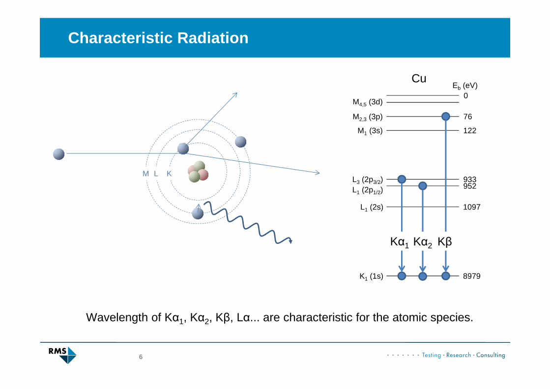
Characteristic Radiation
6
KLM
Eb (eV)0
76
122
933952
1097
8979
M4,5 (3d)
M2,3 (3p)
M1 (3s)
L3 (2p3/2)L1 (2p1/2)
L1 (2s)
K1 (1s)
Kα1 Kα2 Kβ
Cu
Wavelength of Kα1, Kα2, Kβ, Lα... are characteristic for the atomic species.
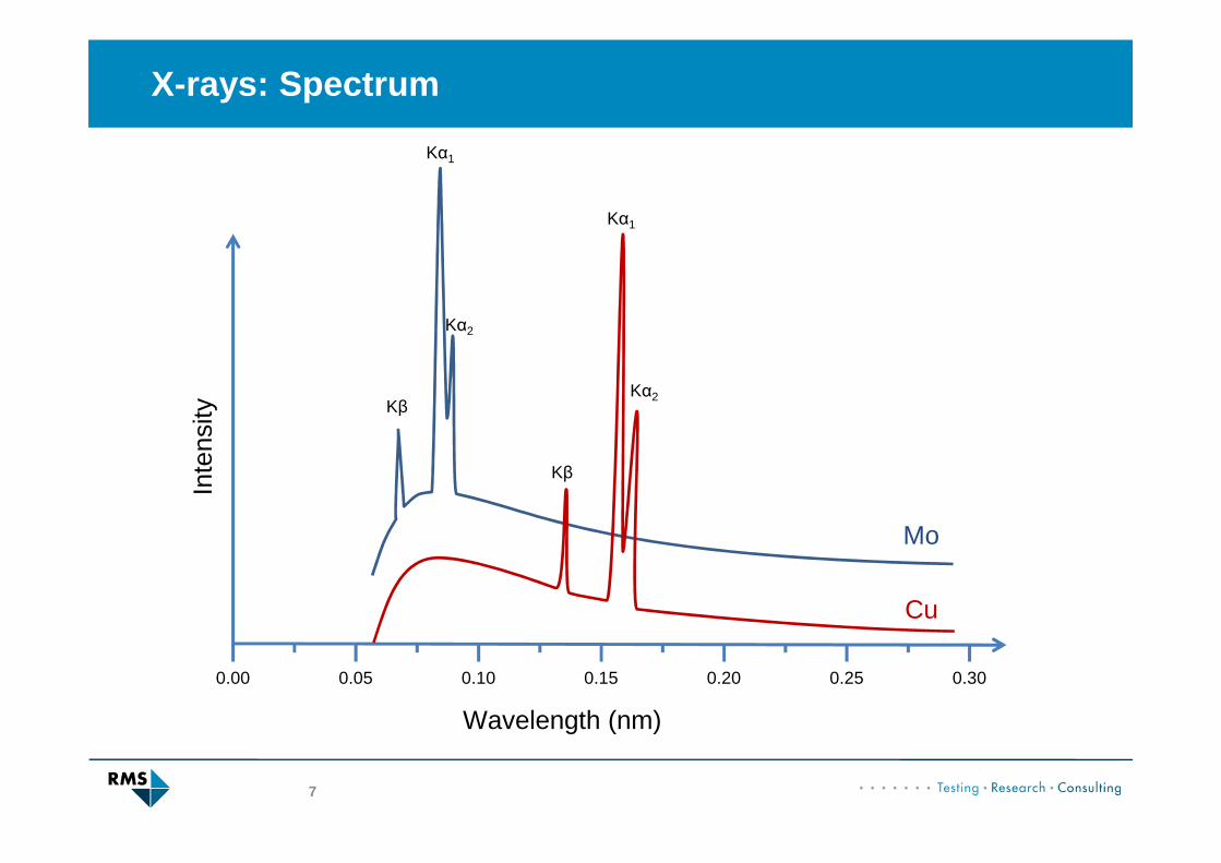
X-rays: Spectrum
7
Wavelength (nm)
Inte
nsity
0.00 0.05 0.10 0.15 0.20 0.25 0.30
Cu
Kα1
Kα2
Kβ
Kα1
Kα2
Kβ
Mo
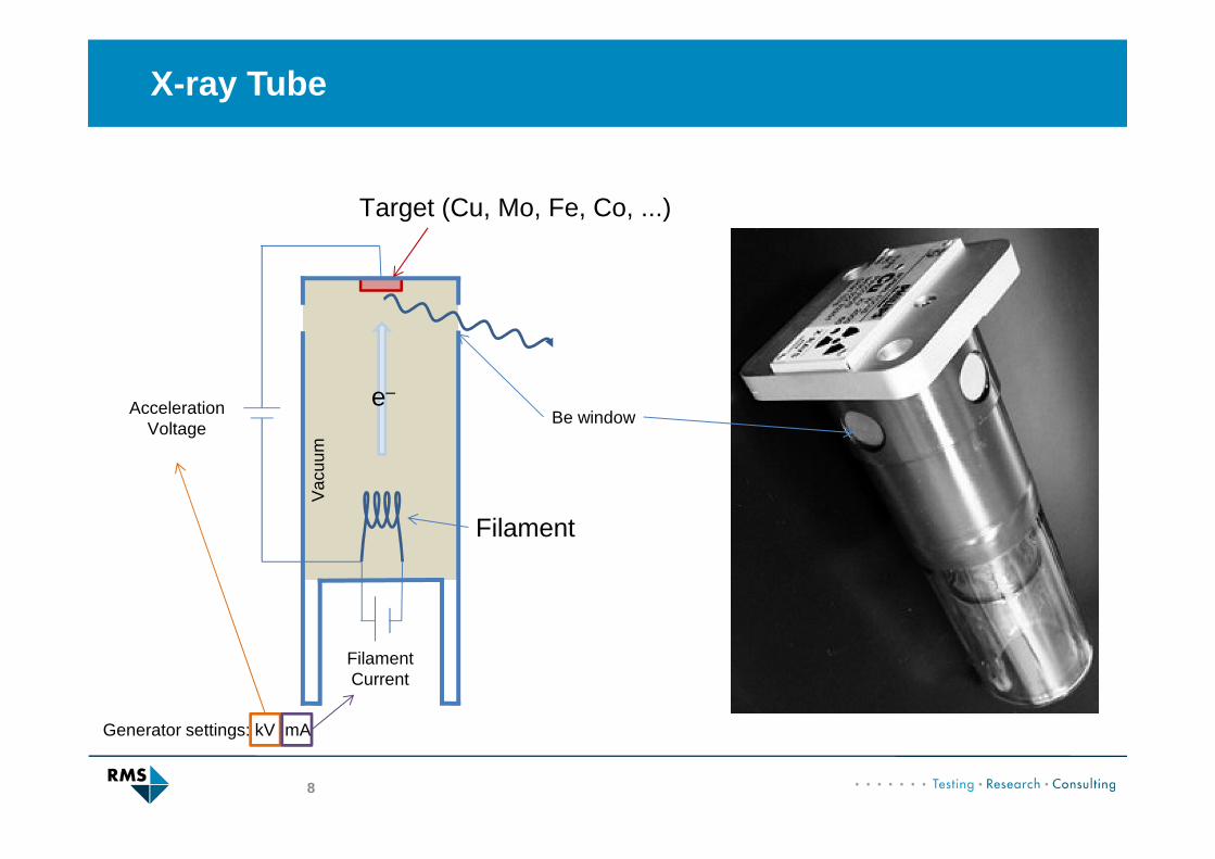
X-ray Tube
8
e‒
Filament
Target (Cu, Mo, Fe, Co, ...)
Be windowAccelerationVoltage
Vac
uum
FilamentCurrent
Generator settings: kV mA

Old X-ray tubes
9
Caution:Beryllium is toxic & carcinogenic!
- Never touch the windows!- Use appropriate covers!
Caution:Beryllium is toxic & carcinogenic!
- Never touch the windows!- Use appropriate covers!
Lifetime of a few years:
- Vacuum decreases� loss of intensity
- Tungsten from filament depositson target� contaminated spectrum (characteristicW spectrum starts to appear)
- Monitor the intensity
- Replace old tubes

Focal Point
10
Typical target size:Length: 10-12 mmWidth: 0.4-1.0 mm
Target
Point focus
Line focus
Take-off angle(typically 6°)

X-rays: Summary
11
• Generated in an X-ray tube
• Spectrum contains Bremsstrahlung (continuous) and characteristic radiation (Kα1, Kα2, Kβ) of target material
• Tube is characterized by:• Target material• Size and shape of target• Aceleration voltage and
current

Diffraction Basics
12
Interaction of X-rays with matter:
- Absorption (photoelectric effect, giving rise to fluorescence)- Elastic scattering (Thomson scattering)- Inelastic scattering (Compton scattering)
Absorption Photoelectric effect, Fluorescence
1. Absorption and ionization2. Relaxation and emission of characteristic radiation
CuKα1
FeKα1
Fe atom
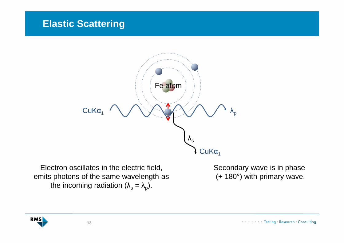
Elastic Scattering
13
Electron oscillates in the electric field,emits photons of the same wavelength as
the incoming radiation (λs = λp).
λp
λs
CuKα1
CuKα1
Fe atom
Secondary wave is in phase (+ 180°) with primary wave.

Crystal Lattice
14
Crystal: Periodic arrangement of atoms/ions/molecules in 3 dimensions.
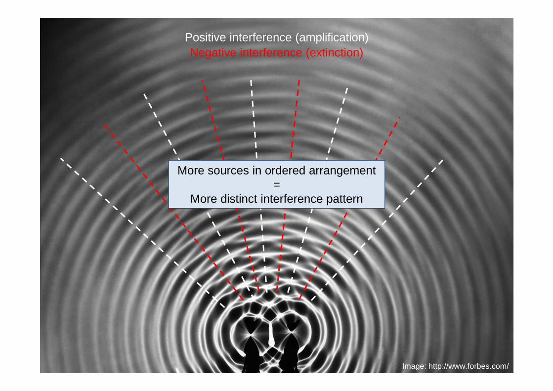
Electrons of each atom become a source ofscattered radiation (spherical waves)
xx.xx.xxxx Tagung15Image: http://www.forbes.com/
Positive interference (amplification)Negative interference (extinction)
More sources in ordered arrangement=
More distinct interference pattern

Bragg’s Law
16
n · λ = 2 · d · sin(θ)
d
λ
θθ 2θ
Diffracted beam looks like a «reflection», but it is scattered radiation

Bragg’s Law
17
CuKα1 = 0.154056 nma = 0.2 nmb = 0.5 nm
ba
b
a
2θ = 45.30°2θ = 17.72°
d = 0.2 nm
d = 0.5 nm
θ = 22.65°θ = 8.86°

Lattice Planes and Miller Indices
18
a
b
Definition:A lattice plane is a planewhich intersects atoms ofa unit cell across the whole3‐dimensional lattice.
d(100)
d(010)
d(110)
d(-210)
- Each lattice plane generates a diffraction peak.
- The 2θ angle of thepeak depends on the plane’s d-spacing.
- Diffraction peaks canbe labelled with the plane’s Miller index.

Single Crystal
19
A single crystal must be rotatedto bring each lattice plane indiffraction condition.
2θ 2θ2θ

Polycrystals, Powders
20
In an ideal powder everypossible orientation ofcrystals occurs.
In a random powderno orientation is preferred.
In an ideal powder all possible diffraction peaksare generated, regardless of sample orientation.
Diffraction Cones
21
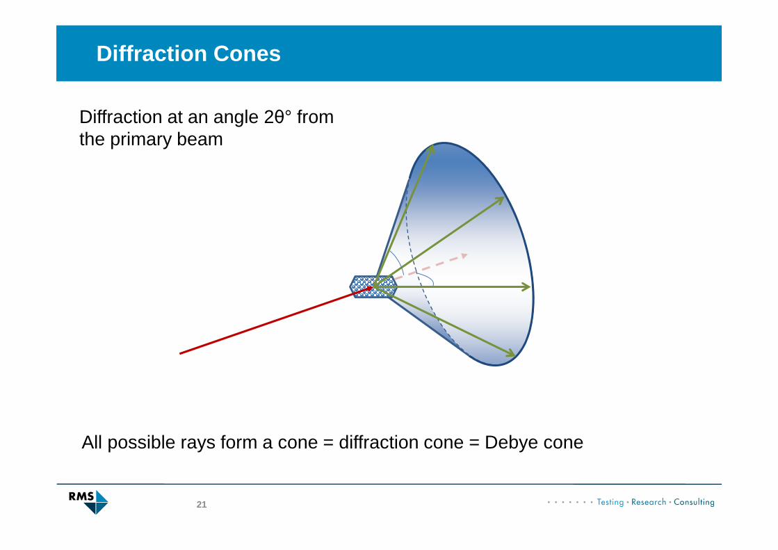
Diffraction at an angle 2θ° fromthe primary beam
All possible rays form a cone = diffraction cone = Debye cone

Diffraction Cones
22
(120)
(100)
(010)
One Debye Cone for each lattice plane spacing (d value)
Powder sample:

Debye Ring
23
Gra
y V
alue
2θ Angle
Gra
y V
alue
2θ Angle

Powder Diffractometer
24
X-ray tube
Primary Beam
PowderSample
Diffraction Cones«Secondary Beams»
X-ray Detectorscanning X-ray intensity
vs. 2θ angle

Powder Diffraction Pattern
25
10 20 30 40 50 600
500
1000
1500
2000In
tens
ity (
cts)
Diffraction Angle (°2θ)
Lesson 2: All about powder diffractometers

Monochromatic X-radiation
26
n · λ = 2 · d · sin(θ)
http://fineartamerica.com
Diffraction angle θ depends on wavelength λ:
Polychromatic X-ray Beam
We need monochromatic X-radiation!
Monochromatic X-radiation
27
Wavelength (nm)
Inte
nsity
0.00 0.05 0.10 0.15 0.20 0.25 0.30
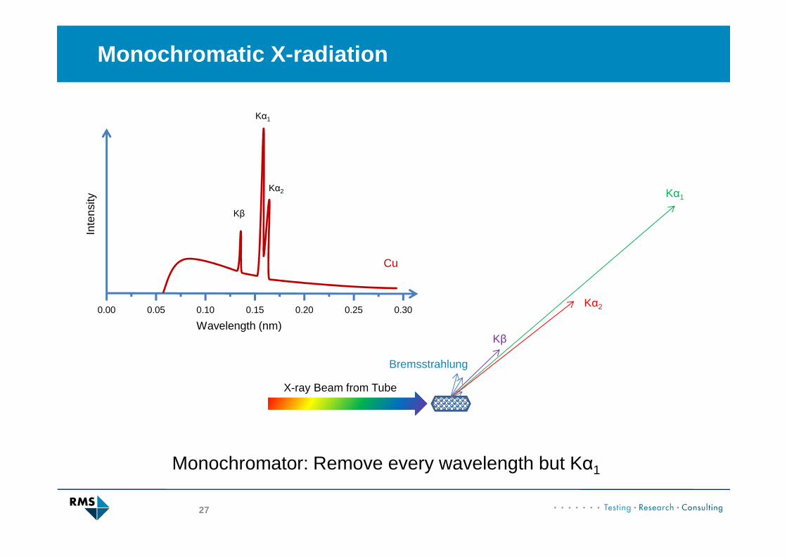
Cu
Kα1
Kα2
Kβ
X-ray Beam from Tube
Bremsstrahlung
Kβ
Kα2
Kα1
Monochromator: Remove every wavelength but Kα1

Monochromator
28
X-radiation is absorbed by solid matter.
Absorption coefficient depends on wavelength.
There are steps (absorption edges) in the spectrum.
Wavelength (nm)
Abs
orpt
ion
Coe
ffic
ient
0.00 0.05 0.10 0.15 0.20 0.25 0.30
Ni
K: 0.14879 nm
L-I: 1.22988 nm
Ni
«K» edge

Ni-Filter
29
Wavelength (nm)
Inte
nsity
0.00 0.05 0.10 0.15 0.20 0.25 0.30
Cu
Kα1
Kα2
Kβ
Ni
Cu Radiation
Ni filter

Ni-Filter
30
Cu Radiation
Ni filter
Ni-filtered Cu Radiation
Wavelength (nm)
Inte
nsity
0.00 0.05 0.10 0.15 0.20 0.25 0.30
Kα1
Kα2
Kβ
Ni
Kβ and Bremsstrahlung attenuated
No elimination of Kα2

Ni-filtered Diffraction Pattern
31
27 28 29 30 31 320
100000
200000
300000
400000
500000In
tens
ity
Diffraction Angle (°2θ)
CuKα1
CuKα2

Ni-filtered Diffraction Pattern
32
27 28 29 30 31 320
2000
4000
6000
8000
10000
12000
14000
16000
18000
20000
Inte
nsity
Diffraction Angle (°2θ)
CuKβ
CuKα1 & CuKα2 duplet
Remaining Bremsstrahlung
Absorption Edge
Impurity
CuKα Satellites
(= CuKα3)

Ni Filter: Primary or Secondary Beam
33
BremsstrahlungKβ
Kα2
Kα1
Cu Radiation
Ni filter
Ni-filtered primary beam
Kα1
Kα2
Cu RadiationNi filter
Primary beam filter
Secondary beam filter

Kβ Filter
34
Target
Element
Kα1 (nm) Kα2 (nm) Kβ (nm) Kβ Filter Absorption
Edge λK (nm)
Cr 0.228975 0.229365 0.20849 V 0.2269
Fe 0.193631 0.194002 0.17567 Mn 0.1896
Co 0.178900 0.179289 0.16208 Fe 0.1744
Ni 0.165794 0.166178 0.15002 Co 0.1608
Cu 0.154059 0.154441 0.139225 Ni 0.1488
Mo 0.709317 0.713607 0.63230 Zr 0.6889
Ag 0.559422 0.563813 0.49708 Rh 0.5339
Birkholz, M. «Thin Film Analysis by X-ray Scattering», Wiley-VCH Verlag GmbH & Co. KGaA, Weinheim, 2006.

Summary: K β Filter
35
Kβ Filter:
- Mostly eliminates Kβ
- Does not eliminate Kα2
- Moderate loss of intensity of Kα1 and Kα2
- Leaves an absorption edge in the foot of the diffraction peaks
- Attenuation of Kβ depends on thickness of filter foil
- Can be placed in the primary or secondary beam

Monochromator Crystal
36
Graphitesingle crystal
Emission Line Wavelength (nm) 2θ Bragg Diffraction
Condition (°)
CuKα1 0.154059 26.57
CuKα2 0.154441 26.64
CuKβ 0.139225 23.97
d (002) = 0.3352 nm
θ = 13.3°
n · λ = 2 · d · sin(θ)
2θ = 26.6°
Kβ and most of the Bremsstrahlung (BS)are not in diffraction condition � Extinction

Monochromator Crystal
37
BSKβ
Kα2
Kα1
Graphite Crystal
Kα1
Si / Ge CrystalsHigh-resolution monochromator
Graphitemonochromator
Kα1 Kα2

Graphite Monochromator
38
27 28 29 30 31 320
1000
2000
3000
4000
5000
6000
7000
8000
9000
10000In
tens
ity
Diffraction Angle (°2θ)
CuKα1
CuKα2

Graphite Monochromator
39
27 28 29 30 31 320
100
200
300
400
500In
tens
ity
Diffraction Angle (°2θ)
CuKα1 & CuKα2 duplet
CuKα Satellites
(= CuKα3)

Monochromator Crystal
40
Monochromator Crystal:
- Completely eliminates Kβ
- Reduces background intensity
- Si / Ge eliminate Kα2, Graphite does not eliminate Kα2
- Severe loss of intensity of Kα1 (and Kα2)
- Graphite crystal can be placed in primary or secondary beam
- Si / Ge crystals are usually placed in the primary beam
- Monochromatic beam is polarized
Energy-Dispersive Detector
41
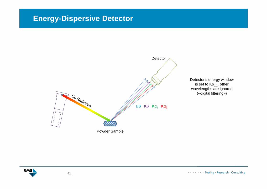
BS Kβ
Powder Sample
Detector
Kα2Kα1
Detector’s energy windowis set to Kα1/2, other
wavelengths are ignored(«digital filtering»)

Energy-Dispersive Detector
42
Energy-dispersive Detector:
- Completely eliminates Kβ
- Reduces background intensity
- Does not eliminate Kα2
- No loss of intensity of Kα1 and Kα2

Summary: Monochromators
43
• Monochromatic X-radiation is required for powder XRD
• Bremsstrahlung and Kβ must be eliminated from thetube’s spectrum
• 3 different types of monochromators:• Kβ filter (Cu tube + Ni filter, Mo tube + Zr filter)• Monochromator crystal• Energy-dispersive detector
• Most systems do not eliminate Kα2!

Overview of Instruments
44
Lab Instrument Monochromator
Uppsala Uni Bruker D8 Ni-Filter
RMS (Uni Bern) Panalytical X’Pert Ni-Filter
RMS (Uni Bern) Panalytical CubiX Graphite
Monochromator
Bruker D8 Panalytical X’Pert Panalytical CubiX