lesson 2 - isa - autenticação · pipelined architectures slides by: pedro tomás additional...
TRANSCRIPT
PIPELINED
ARCHITECTURES Slides by: Pedro Tomás Additional reading: Computer Architecture: A Quantitative Approach”, 5th edition, Appendix C, John L. Hennessy and David A. Patterson, Morgan Kaufmann, 2011
ADVANCED COMPUTER ARCHITECTURES ARQUITECTURAS AVANÇADAS DE COMPUTADORES (AAC)
Advanced Computer Architectures, 2014
Outline
2
Example pipeline architecture for the MIPS processor
Identification of hazard types
Solving hazards:
Pipeline stalls
Data forwarding
Static branch prediction
Delayed branches
Pipelined architectures with multi-cycle functional units
Handling exceptions and interruptions in pipelined processors
Exercises

Advanced Computer Architectures, 2014
RISC architectures
Pipeline of the MIPS processor 3
S
B
A
OP
AL
U
RegisterFile (RF)
S T
RT
RS
PC
IMM
SEL TSEL S
DAWE
DATA
Din
Address WE
Data Memory
Dout
SEL OUT
De
cod
er
DAWE
INST
MEM WRITE
Address
InstructionsMemoryData
INSTRUCTION
PC
Clo
ck +
4
AA BA A B DAWE
DATA
MU
XM
UX
MUX
OP SEL
MU
X
ConditionCheck
Flags
CO
ND
MU
X

Advanced Computer Architectures, 2014
S
B
A
OP
AL
U
RegisterFile (RF)
S T
RT
RS
PC
IMM
SEL TSEL S
DAWE
DATA
Din
Address WE
Data Memory
Dout
SEL OUT
De
cod
er
DAWE
INST
MEM WRITE
Address
InstructionsMemoryData
INSTRUCTION
PC
Clo
ck +
4
AA BA A B DAWE
DATA
MU
XM
UX
MUX
OP SEL
MU
X
ConditionCheck
Flags
CO
ND
MU
X
RISC architectures
Pipeline of the MIPS processor 4
Instruction
Fetch
PC
Increment
Instruction
Decode
Operand
Fetch
Execute
or
Memory
Address
Calculus
Condition
Check
Memory
Access
Write
Back
Compute
Next PC

Advanced Computer Architectures, 2014
Hazard Types
5
Three types of hazards can lead instruction execution to
be delayed:
Structural Hazards:
The processor does not have enough hardware resources to execute
the instruction, e.g.,
MAC (Multiply and accumulate)
𝑀𝐴𝐶 𝑅𝑑, 𝑅𝑎, 𝑅𝑏 𝑅𝑑 ← 𝑅𝑑 + 𝑅𝑎 × 𝑅𝑏
Requires:
- loading three operands from the register file (it has only 2 read ports)
- performing a multiplication plus addition in a single clock-cycle
(the ALU includes an adder and a multiplier, but they are in parallel execution paths)
Advanced Computer Architectures, 2014
Hazard Types
6
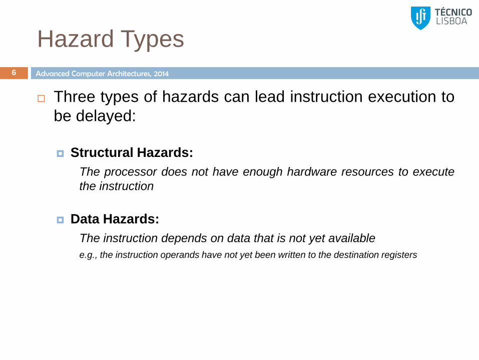
Three types of hazards can lead instruction execution to
be delayed:
Structural Hazards:
The processor does not have enough hardware resources to execute
the instruction
Data Hazards:
The instruction depends on data that is not yet available
e.g., the instruction operands have not yet been written to the destination registers

Advanced Computer Architectures, 2014
Hazard Types
7
Three types of hazards can lead instruction execution to
be delayed:
Structural Hazards:
The processor does not have enough hardware resources to execute
the instruction
Data Hazards:
The instruction depends on data that is not yet available
e.g., the instruction operands have not yet been written to the destination registers
Control Hazards:
The IF stage cannot load instructions from memory because the
resolution of the jump/branch condition (or the destination address) is
not yet known
Advanced Computer Architectures, 2014
Hazard Identification
8
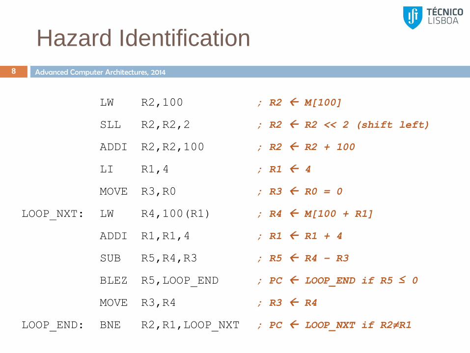
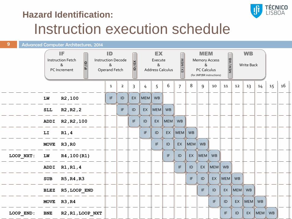
LW R2,100 ; R2 M[100]
SLL R2,R2,2 ; R2 R2 << 2 (shift left)
ADDI R2,R2,100 ; R2 R2 + 100
LI R1,4 ; R1 4
MOVE R3,R0 ; R3 R0 = 0
LOOP_NXT: LW R4,100(R1) ; R4 M[100 + R1]
ADDI R1,R1,4 ; R1 R1 + 4
SUB R5,R4,R3 ; R5 R4 – R3
BLEZ R5,LOOP_END ; PC LOOP_END if R5 ≤ 0
MOVE R3,R4 ; R3 R4
LOOP_END: BNE R2,R1,LOOP_NXT ; PC LOOP_NXT if R2≠R1
Advanced Computer Architectures, 2014
Hazard Identification:
Instruction execution schedule 9
IF /
ID
Instruction Fetch&
PC Increment ID /
EX
EX
/ M
EM
ME
M /
WB
Write Back
IF WB
Instruction Decode&
Operand Fetch
ID
Execute&
Address Calculus
EX
Memory Access&
PC Calculus(for JMP/BR instructions)
MEM
LW R2,100
LI R1,4
MOVE R3,R0
LW R4,100(R1)
SUB R5,R4,R3
BLEZ R5,LOOP_END
ADDI R1,R1,4
MOVE R3,R4
SLL R2,R2,2
LOOP_NXT:
IF ID EX MEM WB
IF ID EX MEM WB
1 2 3 4 5 6 7 8 9 10 11 12 13 14 15 16
IF ID EX MEM WB
IF ID EX MEM WB
IF ID EX MEM WB
IF ID EX MEM WB
IF ID EX MEM WB
IF ID EX MEM WB
IF ID EX MEM WB
IF ID EX MEM WB
BNE R2,R1,LOOP_NXTLOOP_END: IF ID EX MEM WB
ADDI R2,R2,100

Advanced Computer Architectures, 2014
Hazard Identification:
Operations in each pipeline stage 10
IF /
ID
Instruction Fetch&
PC Increment ID /
EX
EX
/ M
EM
ME
M /
WB
Write Back
IF WB
Instruction Decode&
Operand Fetch
ID
Execute&
Address Calculus
EX
Memory Access&
PC Calculus(for JMP/BR instructions)
MEM
LW R2,100
LI R1,4
MOVE R3,R0
LW R4,100(R1)
SUB R5,R4,R3
BLEZ R5,LOOP_END
ADDI R1,R1,4
MOVE R3,R4
SLL R2,R2,2
LOOP_NXT:
IFIDOF
ADDCALC
LOAD WB
IFIDOF
EX -- WB
1 2 3 4 5 6 7 8 9 10 11 12 13 14 15 16
IFIDOF
EX -- WB
IFIDOF
EX -- WB
IFIDOF
EX -- WB
IFIDOF
ADDCALC
LOAD WB
IFIDOF
EX -- WB
IFIDOF
EX -- WB
IFIDOF
CONDCHECK
PCSEL
--
IFIDOF
EX -- WB
BNE R2,R1,LOOP_NXTLOOP_END: IFIDOF
CONDCHECK
PCSEL
--
ADDI R2,R2,100

Advanced Computer Architectures, 2014
LW R2,100
LI R1,4
MOVE R3,R0
LW R4,100(R1)
SUB R5,R4,R3
BLEZ R5,LOOP_END
ADDI R1,R1,4
MOVE R3,R4
SLL R2,R2,2
LOOP_NXT:
IF IMMADDCALC
LOAD WB
IF R2 EX -- WB
1 2 3 4 5 6 7 8 9 10 11 12 13 14 15 16
IF R2 EX -- WB
IF IMM EX -- WB
IF R0 EX -- WB
IF R1ADDCALC
LOAD WB
IF R1 EX -- WB
IF R4,R3 EX -- WB
IF R5CONDCHECK
PCSEL
--
IF R4 EX -- WB
BNE R2,R1,LOOP_NXTLOOP_END: IF R2,R1CONDCHECK
PCSEL
--
ADDI R2,R2,100
R2
R2
R2
R1
R3
R4
R1
R5
R3
Data Hazards:
Read After Write (RAW) 11
IF /
ID
Instruction Fetch&
PC Increment ID /
EX
EX
/ M
EM
ME
M /
WB
Write Back
IF WB
Instruction Decode&
Operand Fetch
ID
Execute&
Address Calculus
EX
Memory Access&
PC Calculus(for JMP/BR instructions)
MEM
Advanced Computer Architectures, 2014
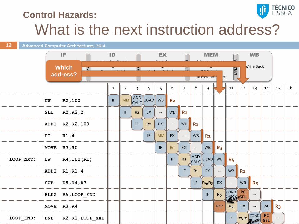
Control Hazards:
What is the next instruction address? 12
IF /
ID
Instruction Fetch&
PC Increment ID /
EX
EX
/ M
EM
ME
M /
WB
Write Back
IF WB
Instruction Decode&
Operand Fetch
ID
Execute&
Address Calculus
EX
Memory Access&
PC Calculus(for JMP/BR instructions)
MEM
LW R2,100
LI R1,4
MOVE R3,R0
LW R4,100(R1)
SUB R5,R4,R3
BLEZ R5,LOOP_END
ADDI R1,R1,4
MOVE R3,R4
SLL R2,R2,2
LOOP_NXT:
IF IMMADDCALC
LOAD WB
IF R2 EX -- WB
1 2 3 4 5 6 7 8 9 10 11 12 13 14 15 16
IF R2 EX -- WB
IF IMM EX -- WB
IF R0 EX -- WB
IF R1ADDCALC
LOAD WB
IF R1 EX -- WB
IF R4,R3 EX -- WB
IF R5CONDCHECK
PCSEL
--
PC? R4 EX -- WB
BNE R2,R1,LOOP_NXTLOOP_END: IF R2,R1CONDCHECK
PCSEL
--
ADDI R2,R2,100
R2
R2
R2
R1
R3
R4
R1
R5
R3
Which
address?

Advanced Computer Architectures, 2014
Data and Control Hazards:
Identification 13
Identification of data and control hazards is performed at
the ID (Instruction Decode) stage
Data hazards:
Identified whenever the register to be read is not yet updated with the
correct value, i.e., the data is going to be written by an instruction in later
pipeline stages
Check in any of the following stages (EX, MEM, WB) if there is an
instruction that writes (WE=1) in the selected register (DA=x)
Data hazard identification can be made by
Directly checking (DAEX,WEEX),(DAMEM,WEMEM),(DAWB,WEWB); or
Creating a table (scoreboard) in ID stage
IF /
ID
Instruction Fetch&
PC Increment ID /
EX
EX
/ M
EM
ME
M /
WB
Write Back
IF WB
Instruction Decode&
Operand Fetch
ID
Execute&
Address Calculus
EX
Memory Access&
PC Calculus(for JMP/BR instructions)
MEM
Requires
reading Rx
Writes on
Rx?
Writes on
Rx?
Writes
on Rx?
Next
instruction
Advanced Computer Architectures, 2014
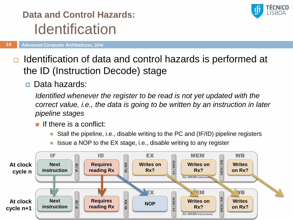
Data and Control Hazards:
Identification 14
Identification of data and control hazards is performed at
the ID (Instruction Decode) stage
Data hazards:
Identified whenever the register to be read is not yet updated with the
correct value, i.e., the data is going to be written by an instruction in later
pipeline stages
If there is a conflict:
Stall the pipeline, i.e., disable writing to the PC and (IF/ID) pipeline registers
Issue a NOP to the EX stage, i.e., disable writing to any register
IF /
ID
Instruction Fetch&
PC Increment ID /
EX
EX
/ M
EM
ME
M /
WB
Write Back
IF WB
Instruction Decode&
Operand Fetch
ID
Execute&
Address Calculus
EX
Memory Access&
PC Calculus(for JMP/BR instructions)
MEM
IF /
ID
Instruction Fetch&
PC Increment ID /
EX
EX
/ M
EM
ME
M /
WB
Write Back
IF WB
Instruction Decode&
Operand Fetch
ID
Execute&
Address Calculus
EX
Memory Access&
PC Calculus(for JMP/BR instructions)
MEM
Requires
reading Rx
Writes on
Rx?
Writes on
Rx?
Writes
on Rx?
Next
instruction
Requires
reading Rx
Next
instruction Writes on
Rx?
Writes
on Rx? NOP
At clock
cycle n
At clock
cycle n+1

Advanced Computer Architectures, 2014
Identification of Data Hazards:
Control logic at the decode stage 15
S
B
A
OP
AL
U
RegisterFile (RF)
S T
RT
RS
PC
IMM
SEL TSEL S
DAWE
DATA
Din
Address WE
Data Memory
Dout
SEL OUT
De
cod
er
DAWE
INST
MEM WRITE
Address
InstructionsMemoryData
INSTRUCTION
PC
Clo
ck +
4
AA BA A B DAWE
DATA
MU
XM
UX
MUX
OP SEL
MU
X
ConditionCheck
Flags
CO
ND
MU
X
ST
AL
L
- STALL IF/ID pipeline- Disable writing to the PC

Advanced Computer Architectures, 2014
Data and Control Hazards:
Identification 16
Identification of data and control hazards is performed
during the ID (Instruction Decode) stage
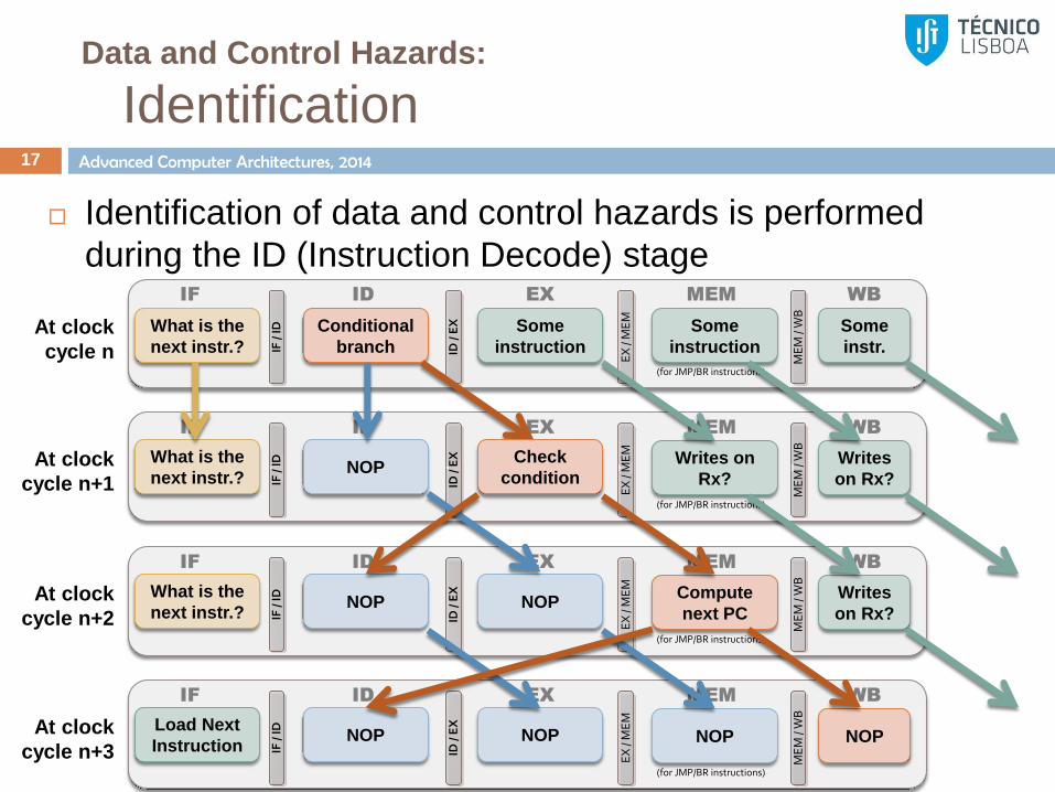
Control hazards:
Identified whenever the current instruction of the control type (i.e., it is a
jump or branch instruction)
Easy identification by simply decoding the instruction
If there is a hazard:
Issue the control instruction to EX stage
Stall the IF/ID Pipeline and Hold PC
A branch instruction at EX Stage requires:
ID issues a NOP to EX
Stall the IF/ID Pipeline and Hold PC
A branch instruction at MEM Stage requires:
ID issues a NOP to EX
Stall the IF/ID Pipeline and Load PC
Advanced Computer Architectures, 2014
Data and Control Hazards:
Identification 17
Identification of data and control hazards is performed
during the ID (Instruction Decode) stage IF
/ ID
Instruction Fetch&
PC Increment ID /
EX
EX
/ M
EM
ME
M /
WB
Write Back
IF WB
Instruction Decode&
Operand Fetch
ID
Execute&
Address Calculus
EX
Memory Access&
PC Calculus(for JMP/BR instructions)
MEM
IF /
ID
Instruction Fetch&
PC Increment ID /
EX
EX
/ M
EM
ME
M /
WB
Write Back
IF WB
Instruction Decode&
Operand Fetch
ID
Execute&
Address Calculus
EX
Memory Access&
PC Calculus(for JMP/BR instructions)
MEM
Conditional
branch
Some
instruction
Some
instruction
Some
instr.
What is the
next instr.?
NOP What is the
next instr.? Writes on
Rx?
Writes
on Rx?
Check
condition
At clock
cycle n
At clock
cycle n+1
IF /
ID
Instruction Fetch&
PC Increment ID /
EX
EX
/ M
EM
ME
M /
WB
Write Back
IF WB
Instruction Decode&
Operand Fetch
ID
Execute&
Address Calculus
EX
Memory Access&
PC Calculus(for JMP/BR instructions)
MEM
NOP What is the
next instr.? Compute
next PC
Writes
on Rx? NOP At clock
cycle n+2
IF /
ID
Instruction Fetch&
PC Increment ID /
EX
EX
/ M
EM
ME
M /
WB
Write Back
IF WB
Instruction Decode&
Operand Fetch
ID
Execute&
Address Calculus
EX
Memory Access&
PC Calculus(for JMP/BR instructions)
MEM
NOP Load Next
Instruction NOP NOP NOP At clock
cycle n+3

Advanced Computer Architectures, 2014
Identification of Control Hazards:
Control logic at the decode stage 18
S
B
A
OP
AL
U
RegisterFile (RF)
S T
RT
RS
PC
IMM
SEL TSEL S
DAWE
DATA
Din
Address WE
Data Memory
Dout
SEL OUT
De
cod
er
DAWE
INST
MEM WRITE
Address
InstructionsMemoryData
INSTRUCTION
PC
Clo
ck +
4
AA BA A B DAWE
DATA
MU
XM
UX
MUX
OP SEL
MU
X
ConditionCheck
Flags
CO
ND
MU
X
ST
AL
LIF
/ID
Sta
llP
C H
old
ST
AL
L In
Advanced Computer Architectures, 2014
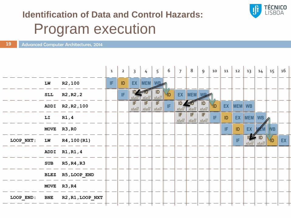
Identification of Data and Control Hazards:
Program execution 19
LW R2,100
LI R1,4
MOVE R3,R0
LW R4,100(R1)
SUB R5,R4,R3
BLEZ R5,LOOP_END
ADDI R1,R1,4
MOVE R3,R4
SLL R2,R2,2
LOOP_NXT:
1 2 3 4 5 6 7 8 9 10 11 12 13 14 15 16
BNE R2,R1,LOOP_NXTLOOP_END:
ADDI R2,R2,100
IF ID
IF
EX MEM WB
ID EX MEM ID
stall ID
stall ID
stall WB ID EX MEM WB
IF stall
IF stall
IF stall
IF ID EX MEM WB ID
stall ID
stall ID
stall ID EX MEM WB
IF stall
IF stall
IF stall
IF ID EX MEM WB
IF ID EX MEM WB
IF ID EX MEM WB ID
stall ID
stall ID EX
Advanced Computer Architectures, 2014
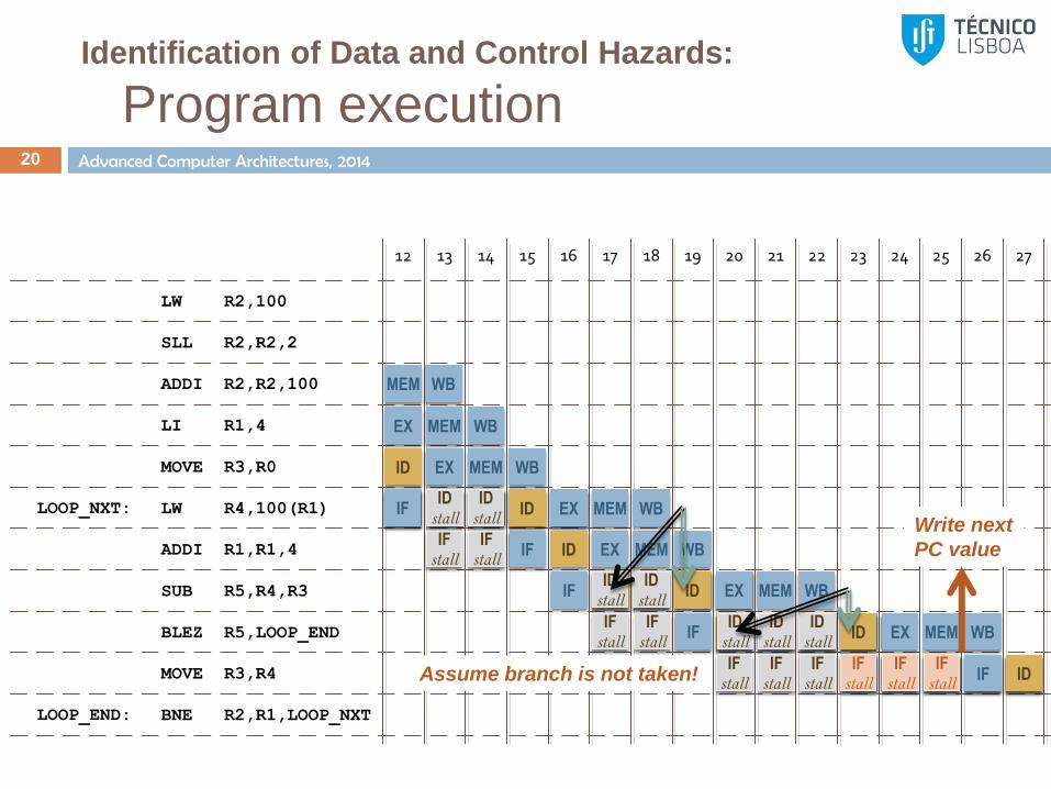
LW R2,100
LI R1,4
MOVE R3,R0
LW R4,100(R1)
SUB R5,R4,R3
BLEZ R5,LOOP_END
ADDI R1,R1,4
MOVE R3,R4
SLL R2,R2,2
LOOP_NXT:
12 13 14 15 16 17 18 19 20 21 22 23 24 25 26 27
BNE R2,R1,LOOP_NXTLOOP_END:
ADDI R2,R2,100
Identification of Data and Control Hazards:
Program execution 20
MEM WB
EX MEM WB
ID EX MEM WB
IF ID EX MEM WB IF ID
stall ID EX
IF ID EX MEM WB
MEM WB
IF ID EX MEM WB
ID stall
IF stall
IF stall
ID stall
ID EX MEM WB ID
stall
IF ID EX MEM WB IF
stall IF
stall ID
stall ID
stall ID
stall ID EX MEM WB
IF stall
IF stall
IF stall
IF ID EX MEM WB Assume branch is not taken!
Write next
PC value
IF stall
IF stall
IF stall
IF ID

Advanced Computer Architectures, 2014
LW R2,100
LI R1,4
MOVE R3,R0
LW R4,100(R1)
SUB R5,R4,R3
BLEZ R5,LOOP_END
ADDI R1,R1,4
MOVE R3,R4
SLL R2,R2,2
LOOP_NXT:
20 21 22 23 24 25 26 27 28 29 30 31 32 33 34 35
BNE R2,R1,LOOP_NXTLOOP_END:
ADDI R2,R2,100
Identification of Data and Control Hazards:
Program execution 21
WB EX MEM WB
ID EX MEM WB ID
stall ID
stall ID
stall ID EX MEM WB
IF stall
IF stall
IF stall
IF ID EX MEM WB IF
stall IF
stall IF
stall IF ID EX MEM WB
IF ID EX MEM WB
TOTAL NUMBER OF CLOCK CYCLES TO EXECUTE 1
ITERATION OF THE ALGORITHM: 31
IPC (Instructions per cycle) = 11/31 = 0.35
CPI (Cycles per instruction) = 31/11 = 2.8
Advanced Computer Architectures, 2014
Solving Data Hazards:
Data Hazards at the WB stage 22
The logic at the WB stage has a short propagation path
In many cases, the WB stage requires only half the clock cycle,
instead of the full clock cycle
Data hazards at the WB stage can be easily solved by
writing data at half-cycle
Change the register file so that writing is performed on the falling
edge
Advanced Computer Architectures, 2014
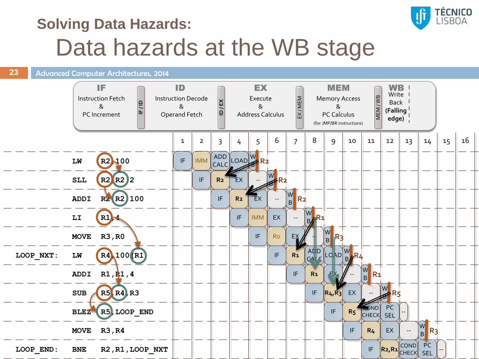
Solving Data Hazards:
Data hazards at the WB stage 23
LW R2,100
LI R1,4
MOVE R3,R0
LW R4,100(R1)
SUB R5,R4,R3
BLEZ R5,LOOP_END
ADDI R1,R1,4
MOVE R3,R4
SLL R2,R2,2
LOOP_NXT:
IF IMMADDCALC
LOADWB
IF R2 EX --
1 2 3 4 5 6 7 8 9 10 11 12 13 14 15 16
IF R2 EX --
IF IMM EX --
IF R0 EX --
IF R1ADDCALC
LOAD
IF R1 EX --
IF R4,R3 EX --
IF R5CONDCHECK
PCSEL
--
IF R4 EX --
BNE R2,R1,LOOP_NXTLOOP_END: IF R2,R1CONDCHECK
PCSEL
--
ADDI R2,R2,100
R2
WB R2
WB R2
WB R1
WB R3
WB R4
WB R1
WB R5
WB R3
IF /
ID
Instruction Fetch&
PC Increment ID /
EX
EX
/ M
EM
ME
M /
WB Write
Back(Falling edge)
IF WB
Instruction Decode&
Operand Fetch
ID
Execute&
Address Calculus
EX
Memory Access&
PC Calculus(for JMP/BR instructions)
MEM
Advanced Computer Architectures, 2014
Solving Data Hazards:
Data hazards at the EX/MEM stage 24
In reality the execution unit (or data memory) does not
actually need the data to be ready at the ID stage
What do we need?
Data must be valid when the operation at the EX stage starts
(or the MEM stage, if it is the data to be stored)
Operands do not need to be fetched from the register file
(RF); instead, they can be read directly from the execution
unit that generates it
Solution:
Add forwarding paths from later to initial pipeline stages
Predict at ID stage if the hazard will be solved at EX stage
Advanced Computer Architectures, 2014
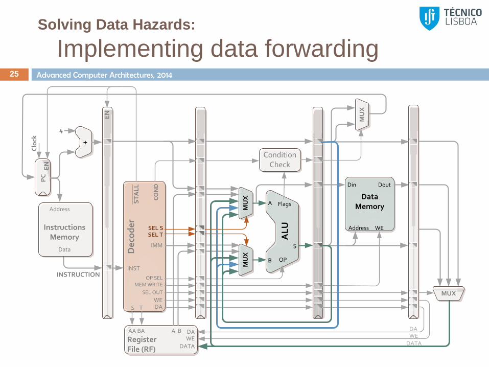
Solving Data Hazards:
Implementing data forwarding 25
S
B
A
OP
AL
U
RegisterFile (RF)
S T
IMM
SEL TSEL S
DAWE
DATA
Din
Address WE
Data Memory
Dout
SEL OUT
De
cod
er
DAWE
INST
MEM WRITE
Address
InstructionsMemory
Data
INSTRUCTION
PC
Clo
ck +
4
AA BA A B DAWE
DATA
MU
XM
UX
MUX
OP SEL
MU
X
ConditionCheck
Flags
EN
EN
CO
ND
ST
AL
L

Advanced Computer Architectures, 2014
Solving Data Hazards:
Implementing data forwarding 26
If the operand value comes from the register file, check
the pipeline stages in the following order:
1. MEM stage (EX data / PC)
2. WB stage
3. Register value coming from ID stage
Later on…
Examples of forwarding paths with different architectures
Examples where forwarding does not solve all data hazards
Advanced Computer Architectures, 2014
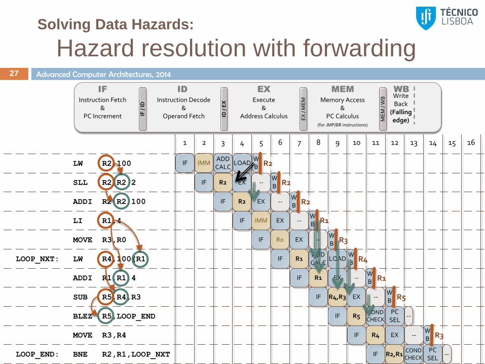
Solving Data Hazards:
Hazard resolution with forwarding 27
LW R2,100
LI R1,4
MOVE R3,R0
LW R4,100(R1)
SUB R5,R4,R3
BLEZ R5,LOOP_END
ADDI R1,R1,4
MOVE R3,R4
SLL R2,R2,2
LOOP_NXT:
IF IMMADDCALC
LOADWB
IF R2 EX --
1 2 3 4 5 6 7 8 9 10 11 12 13 14 15 16
IF R2 EX --
IF IMM EX --
IF R0 EX --
IF R1ADDCALC
LOAD
IF R1 EX --
IF R4,R3 EX --
IF R5CONDCHECK
PCSEL
--
IF R4 EX --
BNE R2,R1,LOOP_NXTLOOP_END: IF R2,R1CONDCHECK
PCSEL
--
ADDI R2,R2,100
R2
WB R2
WB R2
WB R1
WB R3
WB R4
WB R1
WB R5
WB R3
IF /
ID
Instruction Fetch&
PC Increment ID /
EX
EX
/ M
EM
ME
M /
WB Write
Back(Falling edge)
IF WB
Instruction Decode&
Operand Fetch
ID
Execute&
Address Calculus
EX
Memory Access&
PC Calculus(for JMP/BR instructions)
MEM
Advanced Computer Architectures, 2014
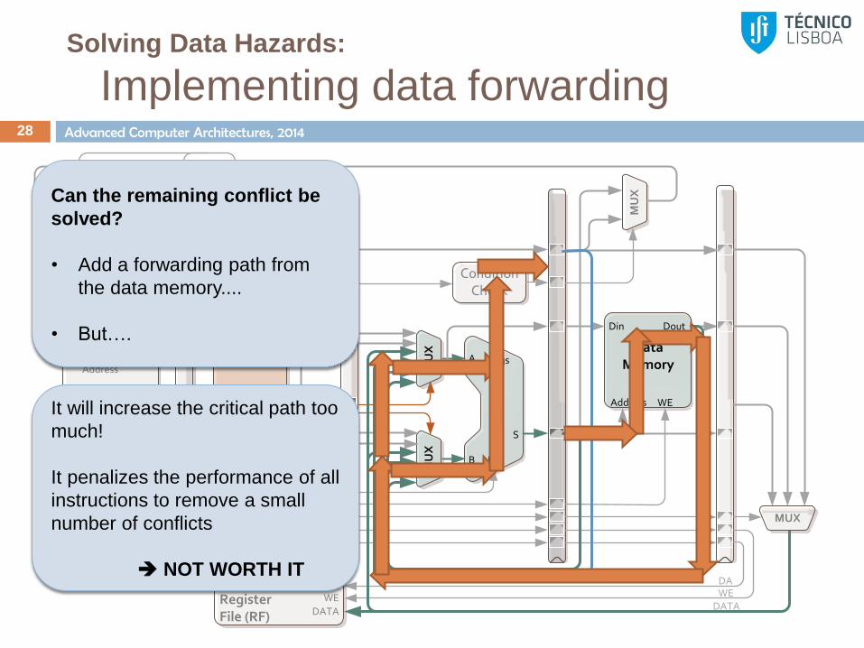
Solving Data Hazards:
Implementing data forwarding 28
S
B
A
OP
AL
U
RegisterFile (RF)
S T
IMM
SEL TSEL S
DAWE
DATA
Din
Address WE
Data Memory
Dout
SEL OUT
De
cod
er
DAWE
INST
MEM WRITE
Address
InstructionsMemory
Data
INSTRUCTION
PC
Clo
ck +
4
AA BA A B DAWE
DATA
MU
XM
UX
MUX
OP SEL
MU
X
ConditionCheck
Flags
EN
EN
CO
ND
ST
AL
L
Can the remaining conflict be
solved?
• Add a forwarding path from
the data memory....
• But….
It will increase the critical path too
much!
It penalizes the performance of all
instructions to remove a small
number of conflicts
NOT WORTH IT
Advanced Computer Architectures, 2014
Solving Data Hazards:
Forwarding and performance 29
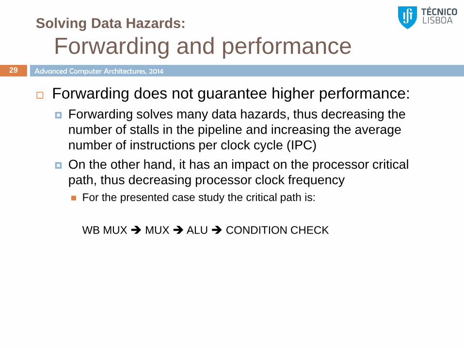
Forwarding does not guarantee higher performance:
Forwarding solves many data hazards, thus decreasing the
number of stalls in the pipeline and increasing the average
number of instructions per clock cycle (IPC)
On the other hand, it has an impact on the processor critical
path, thus decreasing processor clock frequency
For the presented case study the critical path is:
WB MUX MUX ALU CONDITION CHECK
Advanced Computer Architectures, 2014
Solving Data Hazards:
Forwarding and performance 30
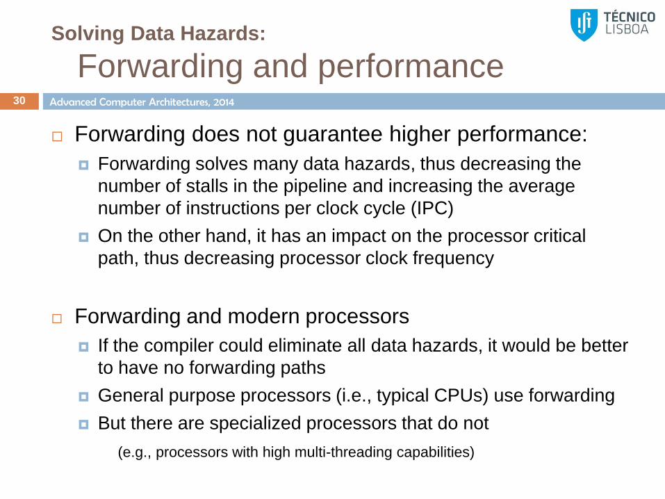
Forwarding does not guarantee higher performance:
Forwarding solves many data hazards, thus decreasing the
number of stalls in the pipeline and increasing the average
number of instructions per clock cycle (IPC)
On the other hand, it has an impact on the processor critical
path, thus decreasing processor clock frequency
Forwarding and modern processors
If the compiler could eliminate all data hazards, it would be better
to have no forwarding paths
General purpose processors (i.e., typical CPUs) use forwarding
But there are specialized processors that do not
(e.g., processors with high multi-threading capabilities)
Delayed branch
Static branch prediction
Solving control hazards 31

Advanced Computer Architectures, 2014
RISC architectures
Pipeline of the MIPS processor 32
S
B
A
OP
AL
U
RegisterFile (RF)
S T
RT
RS
PC
IMM
SEL TSEL S
DAWE
DATA
Din
Address WE
Data Memory
Dout
SEL OUT
De
cod
er
DAWE
INST
MEM WRITE
Address
InstructionsMemoryData
INSTRUCTION
PC
Clo
ck +
4
AA BA A B DAWE
DATA
MU
XM
UX
MUX
OP SEL
MU
X
ConditionCheck
Flags
CO
ND
MU
X
Advanced Computer Architectures, 2014
Pipelined architecture
Data Forwarding & stall on control hazards 33
5 stage pipeline:
IF, ID, EX, MEM, WB
Data hazards solved by:
WB stages uses half cycle (writes on falling edge)
Forwarding from MEM and WB stages to EX
Control hazards:
Stall until dependency is solved (next PC is known)
Advanced Computer Architectures, 2014
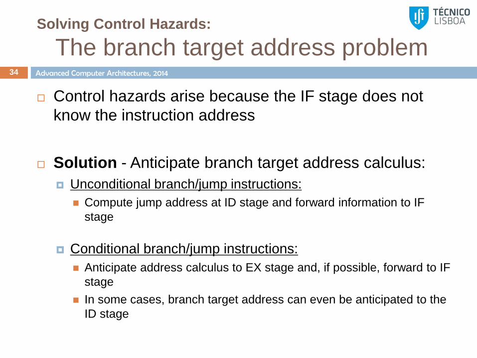
Solving Control Hazards:
The branch target address problem 34
Control hazards arise because the IF stage does not
know the instruction address
Solution - Anticipate branch target address calculus:
Unconditional branch/jump instructions:
Compute jump address at ID stage and forward information to IF
stage
Conditional branch/jump instructions:
Anticipate address calculus to EX stage and, if possible, forward to IF
stage
In some cases, branch target address can even be anticipated to the
ID stage

Advanced Computer Architectures, 2014
Solving Control Hazards:
The branch target address problem 35
Control hazards arise because the IF stage does not
know the instruction address
Solution - Anticipate branch target address calculus
Problems:
Branches still generate stall cycles!
The additionally required circuits (e.g., adders) have a low utilization
May impact the processor critical path thus decreasing clock
frequency
Do not solve the problem, especially in processors with deep
pipelines (e.g., modern Intel processors have 14 stages)

Advanced Computer Architectures, 2014
Solving Control Hazards:
Stall cycles 36
How many stall cycles must be introduced to solve
control hazards due to conditional and unconditional
jumps considering that:
a) The next PC is computed at the EX stage and directly
forwarded to the IF stage
b) The next PC is computed at the ID stage for unconditional
branches and at the EX stage for conditional ones.
However, one cycle is required to send the next PC value to
the IF stage
In which condition can control instructions be solved
without introducing any stall cycle

Advanced Computer Architectures, 2014
Solving Control Hazards:
Delayed branch 37
Execution of the instructions following the branch,
independently of the condition:
E.g., for an N delay slot branch, the processor always executes
the following N instructions.
Static solution which must be solved by the compiler:
Whenever possible use a valid instruction, typically one before the
branch
Branch instructions cannot occupy delay slots
If no other solution is viable, insert a NOP
The typical compiler success for a RISC processor with one
delay slot is around 50%
Advanced Computer Architectures, 2014
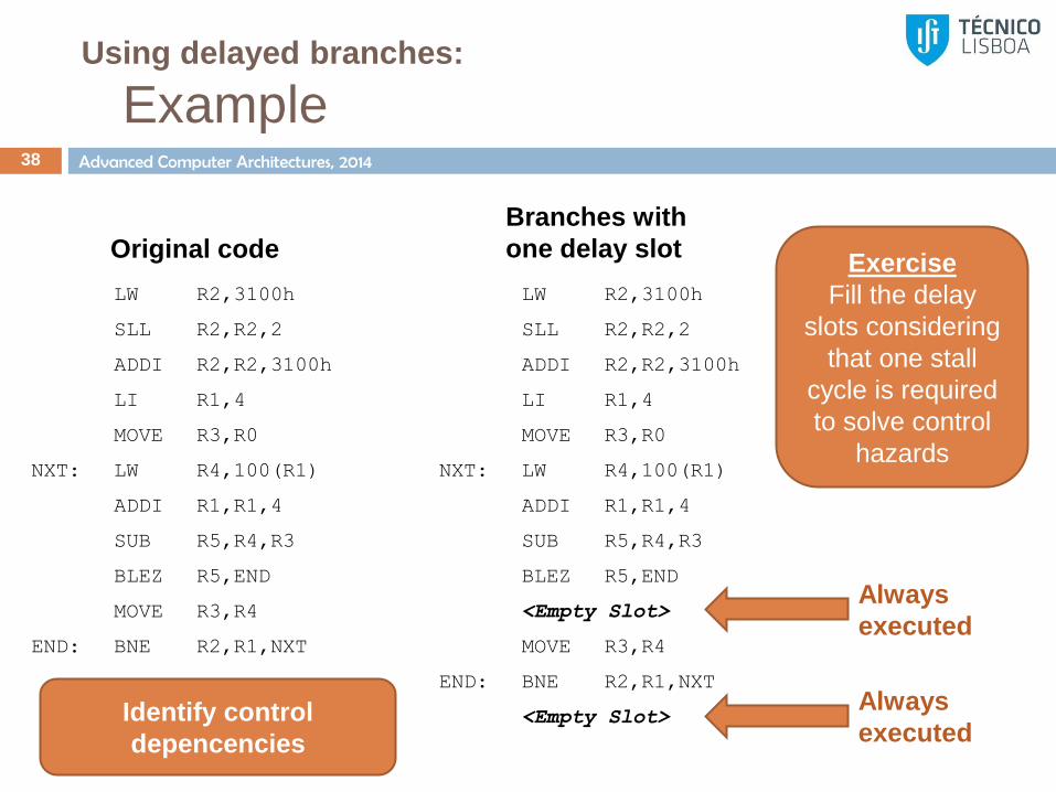
Using delayed branches:
Example 38
LW R2,3100h
SLL R2,R2,2
ADDI R2,R2,3100h
LI R1,4
MOVE R3,R0
NXT: LW R4,100(R1)
ADDI R1,R1,4
SUB R5,R4,R3
BLEZ R5,END
MOVE R3,R4
END: BNE R2,R1,NXT
Original code
LW R2,3100h
SLL R2,R2,2
ADDI R2,R2,3100h
LI R1,4
MOVE R3,R0
NXT: LW R4,100(R1)
ADDI R1,R1,4
SUB R5,R4,R3
BLEZ R5,END
<Empty Slot>
MOVE R3,R4
END: BNE R2,R1,NXT
<Empty Slot>
Branches with
one delay slot
Always
executed
Always
executed
Exercise
Fill the delay
slots considering
that one stall
cycle is required
to solve control
hazards
Identify control
depencencies
Advanced Computer Architectures, 2014
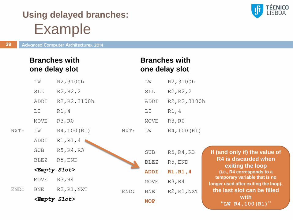
Using delayed branches:
Example 39
LW R2,3100h
SLL R2,R2,2
ADDI R2,R2,3100h
LI R1,4
MOVE R3,R0
NXT: LW R4,100(R1)
SUB R5,R4,R3
BLEZ R5,END
ADDI R1,R1,4
MOVE R3,R4
END: BNE R2,R1,NXT
NOP
Branches with
one delay slot
LW R2,3100h
SLL R2,R2,2
ADDI R2,R2,3100h
LI R1,4
MOVE R3,R0
NXT: LW R4,100(R1)
ADDI R1,R1,4
SUB R5,R4,R3
BLEZ R5,END
<Empty Slot>
MOVE R3,R4
END: BNE R2,R1,NXT
<Empty Slot>
Branches with
one delay slot
If (and only if) the value of
R4 is discarded when
exiting the loop (i.e., R4 corresponds to a
temporary variable that is no
longer used after exiting the loop),
the last slot can be filled
with “LW R4,100(R1)”

Advanced Computer Architectures, 2014
Alternative approach:
Static branch prediction 40
Two techniques:
Static Not Taken branch prediction
Fetch the next instruction considering that no branch is taken
When the branch is solved, perform one of the following
options:
a) The branch was correctly predicted as not taken keep execution
b) The prediction was incorrect clear all instructions that are
already on the pipeline and fetch the correct instruction
On average, the efficiency of static not taken branch prediction
is around 50%
Static Taken branch prediction
Limited gains since the target branch address is only known
in later pipeline stages
Pipelining and hazard resolution with
(pipelined) multi-cycle functional units
Super-pipelining 44

Advanced Computer Architectures, 2014
Advanced pipeline architectures
Support for multi-cycle functional units 45
Some arithmetic operations are too complex to be
performed on a single clock cycle, e.g.,
Integer division
Floating point add, multiply, divide, …
In those cases, the processor is characterized by
multiple functional units on the EX stage
To increase throughput, the functional units can be pipelined
Multiple instructions can be simultaneously executed in the
EX stage, in different or the same functional unit
Advanced Computer Architectures, 2014
Advanced pipeline architectures
Example multi-cycle functional units 46
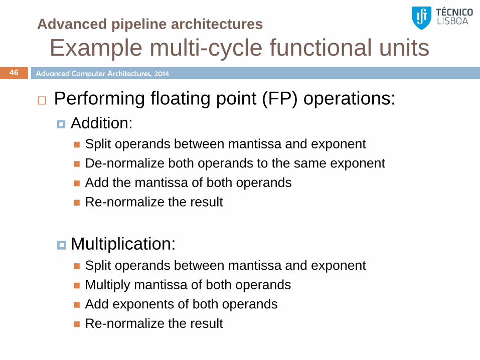
Performing floating point (FP) operations:
Addition:
Split operands between mantissa and exponent
De-normalize both operands to the same exponent
Add the mantissa of both operands
Re-normalize the result
Multiplication: Split operands between mantissa and exponent
Multiply mantissa of both operands
Add exponents of both operands
Re-normalize the result
Advanced Computer Architectures, 2014
Advanced pipeline architectures
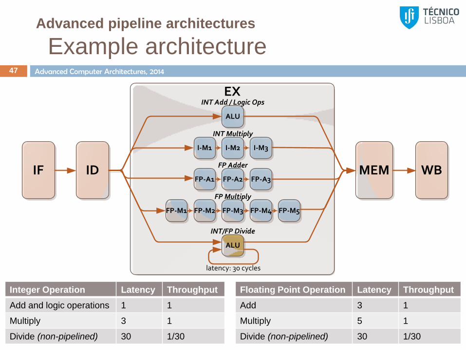
Example architecture 47
Integer Operation Latency Throughput
Add and logic operations 1 1
Multiply 3 1
Divide (non-pipelined) 30 1/30
Floating Point Operation Latency Throughput
Add 3 1
Multiply 5 1
Divide (non-pipelined) 30 1/30
IF ID
EX
MEM WB
ALU
I-M2 I-M3I-M1
INT Multiply
FP-A2 FP-A3FP-A1
FP Adder
FP-M3 FP-M4FP-M2
FP Multiply
FP-M5FP-M1
INT Add / Logic Ops
ALU
INT/FP Divide
latency: 30 cycles

Advanced Computer Architectures, 2014
Advanced pipeline architectures
Additional structural hazards 48
IF ID
EX
MEM WB
ALU
I-M2 I-M3I-M1
INT Multiply
FP-A2 FP-A3FP-A1
FP Adder
FP-M3 FP-M4FP-M2
FP Multiply
FP-M5FP-M1
INT Add / Logic Ops
ALU
INT/FP Divide
latency: 30 cycles
A division operation cannot be issued to the EX stage if another is
already being performed
Division in
execution
New division
instruction

Advanced Computer Architectures, 2014
Advanced pipeline architectures
Additional structural hazards 49
IF ID
EX
MEM WB
ALU
I-M2 I-M3I-M1
INT Multiply
FP-A2 FP-A3FP-A1
FP Adder
FP-M3 FP-M4FP-M2
FP Multiply
FP-M5FP-M1
INT Add / Logic Ops
ALU
INT/FP Divide
latency: 30 cycles
Execution
Finished
Bandwidth:
2 words
Multiple functional units finish execution at the same clock cycle, but the EX output bus does not have enough bandwidth
The bandwidth can be increased, but at the cost of additional hardware and low utilization

Advanced Computer Architectures, 2014
Advanced pipeline architectures
Additional structural hazards 50
IF ID
EX
MEM WB
ALU
I-M2 I-M3I-M1
INT Multiply
FP-A2 FP-A3FP-A1
FP Adder
FP-M3 FP-M4FP-M2
FP Multiply
FP-M5FP-M1
INT Add / Logic Ops
ALU
INT/FP Divide
latency: 30 cycles
Only one word
can be written
to the RF
2 Words
Reach the
WB stage
Multiple instructions reach the WB stage at the same time, but the
register file can only write one word per clock cycle.

Advanced Computer Architectures, 2014
Advanced pipeline architectures
More data hazards 51
Read after Write (RAW) hazards are more problematic
since functional unit latencies are longer
Some modern processors save one cycle by forwarding data
before floating point normalization
MUL.D F2,F1,F0
ADD.D F5,F2,F0
IF
IF
ID
ID
M1
Stall
M2
Stall
M3
Stall
M4
Stall
M5
A1 A2 A3
MEM WB
MEM WB
MUL.D F2,F1,F0
ADD.D F5,F2,F0
IF
IF
ID
ID
M1
Stall
M2
Stall
M3
Stall
M4 M5
A1 A2 A3
MEM WB
MEM WB

Advanced Computer Architectures, 2014
Advanced pipeline architectures
More data hazards 52
Since instructions do not reach the WB stage in order,
new write after write hazards (WAW) can be generated
Write after Read (WAR) hazards do not occur because
reading is performed on ID stage
The resulting value of F2 is given by the first and not the second
instruction
MUL.D F2,F1,F0
ADD.D F2,F4,F0
IF
IF
ID
ID
M1 M2 M3 M4 M5
A1 A2 A3
MEM WB
MEM WB
Advanced Computer Architectures, 2014
Super-pipelining architectures
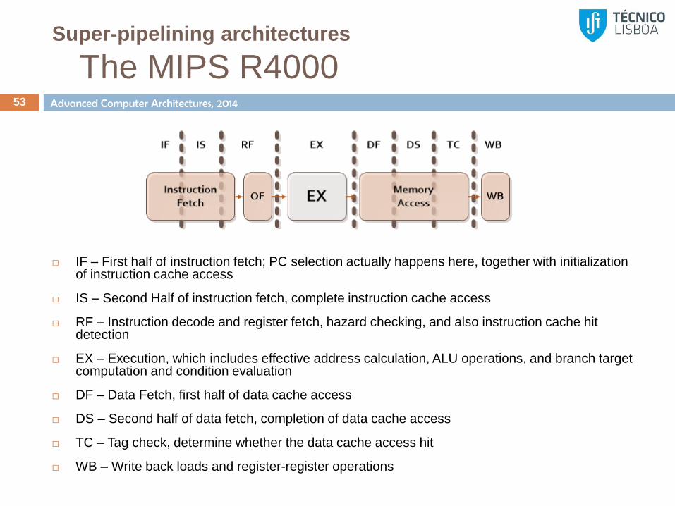
The MIPS R4000 53
IF – First half of instruction fetch; PC selection actually happens here, together with initialization of instruction cache access
IS – Second Half of instruction fetch, complete instruction cache access
RF – Instruction decode and register fetch, hazard checking, and also instruction cache hit detection
EX – Execution, which includes effective address calculation, ALU operations, and branch target computation and condition evaluation
DF – Data Fetch, first half of data cache access
DS – Second half of data fetch, completion of data cache access
TC – Tag check, determine whether the data cache access hit
WB – Write back loads and register-register operations
Interruptions and exceptions 54
Exceptions (associated with a process):
Division by zero
Invalid memory accesses
Page faults
Breakpoints
…
Interruptions (caused by external devices):
I/O devices such as HDD, keyboard or mouse

Advanced Computer Architectures, 2014
Interruptions and exceptions
55
LW R2,3100h
SLL R2,R2,2
ADDI R2,R2,3100h
LI R1,4
External interrupt (e.g., HDD)
MOVE R3,R0
NXT: LW R4,100(R1)
ADDI R1,R1,4
SUB R5,R4,R3
BLEZ R5,END
MOVE R3,R4
END: BNE R2,R1,NXT
Save context
...
LD R1,10(R2)
LD R3,50(R4)
DADD R1,R1,R3
SD 50(R2),R1
...
Restore context
Save PC and switch to
privileged mode
Go back to user mode
and restore PC
Complex exceptions such as page fault
require returning to the original instruction
Advanced Computer Architectures, 2014
Interruptions and exceptions
56
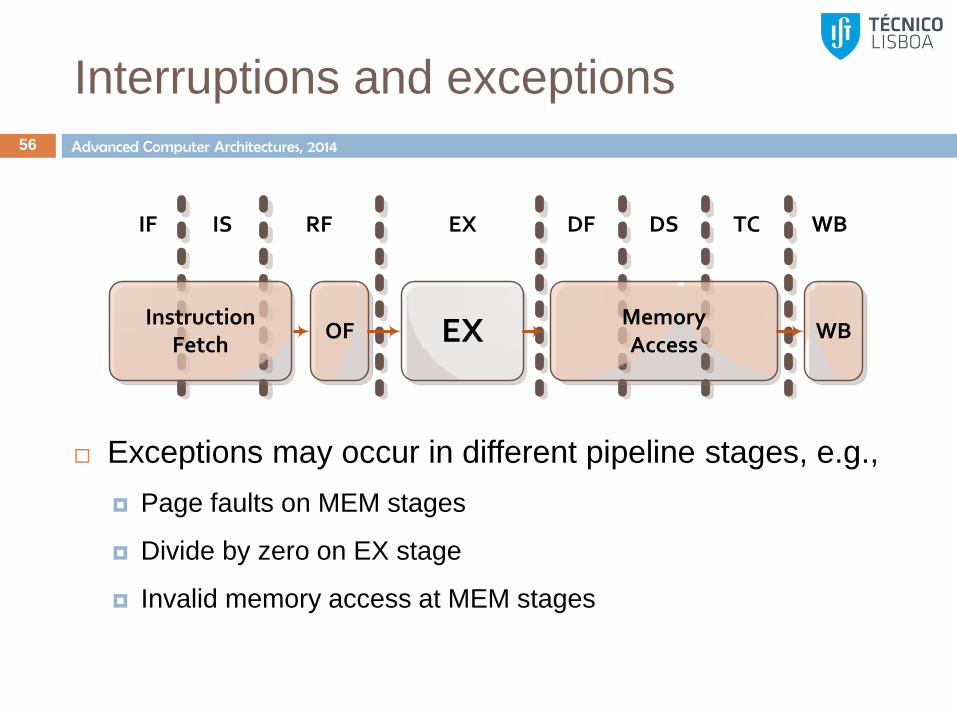
Exceptions may occur in different pipeline stages, e.g.,
Page faults on MEM stages
Divide by zero on EX stage
Invalid memory access at MEM stages
OFInstruction
Fetch EX MemoryAccess
WB
IF IS RF EX DF DS TC WB
Advanced Computer Architectures, 2014
Interruptions and exceptions
57
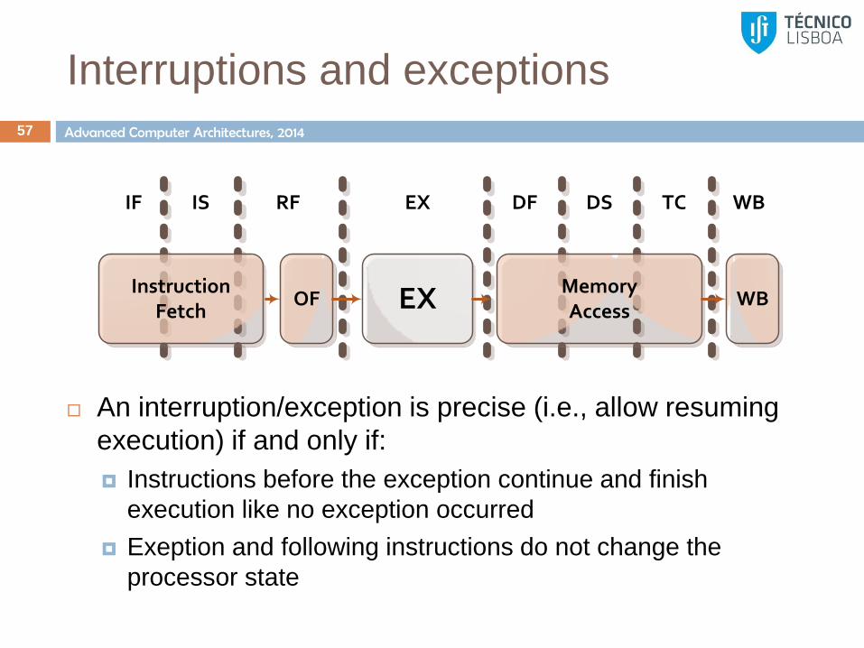
An interruption/exception is precise (i.e., allow resuming
execution) if and only if:
Instructions before the exception continue and finish
execution like no exception occurred
Exeption and following instructions do not change the
processor state
OFInstruction
Fetch EX MemoryAccess
WB
IF IS RF EX DF DS TC WB
Advanced Computer Architectures, 2014
Handling interruptions/exceptions
58
To handle the interruption the control unit:
Introduces a trap instruction at the IF stage
The operating system (OS) routine that handles the
exception/interruption saves the processor context on entry (i.e., the
value of all general and special purpose registers) and restores the
value on exit
Instructions following the exception are allowed to finish execution
Instruction between the exception and the trap are replaced with a
NOP
Deeply pipelined processors with multi-cycle functional units
or out-of-order execution may have operating modes that do
not guarantee the resuming correctness.
Advanced Computer Architectures, 2014
Handling interruptions/exceptions
Problems due to pipelined execution 59
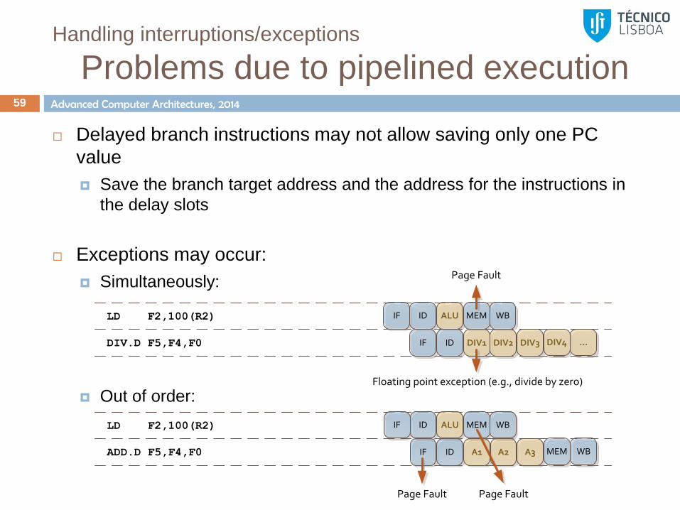
Delayed branch instructions may not allow saving only one PC
value
Save the branch target address and the address for the instructions in
the delay slots
Exceptions may occur:
Simultaneously:
Out of order:
LD F2,100(R2)
ADD.D F5,F4,F0
IF
IF
ID
ID
ALU
A1 A2 A3
MEM WB
MEM WB
Page Fault Page Fault
LD F2,100(R2)
DIV.D F5,F4,F0
IF
IF
ID
ID
ALU
DIV1 DIV2 DIV3
MEM WB
DIV4 ...
Floating point exception (e.g., divide by zero)
Page Fault
Advanced Computer Architectures, 2014
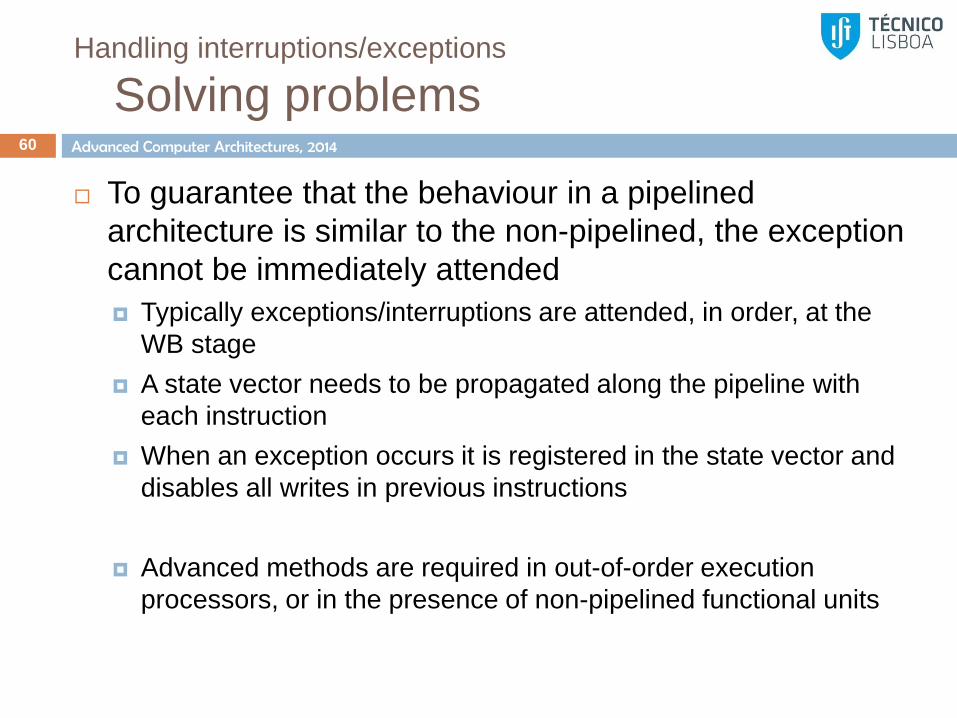
Handling interruptions/exceptions
Solving problems 60
To guarantee that the behaviour in a pipelined
architecture is similar to the non-pipelined, the exception
cannot be immediately attended
Typically exceptions/interruptions are attended, in order, at the
WB stage
A state vector needs to be propagated along the pipeline with
each instruction
When an exception occurs it is registered in the state vector and
disables all writes in previous instructions
Advanced methods are required in out-of-order execution
processors, or in the presence of non-pipelined functional units
Speedup from pipelining
Improving performance by re-scheduling instructions
Next lesson 61
Exercises 62
Advanced Computer Architectures, 2014
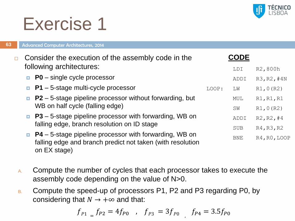
Exercise 1 63
Consider the execution of the assembly code in the
following architectures:
P0 – single cycle processor
P1 – 5-stage multi-cycle processor
P2 – 5-stage pipeline processor without forwarding, but
WB on half cycle (falling edge)
P3 – 5-stage pipeline processor with forwarding, WB on
falling edge, branch resolution on ID stage
P4 – 5-stage pipeline processor with forwarding, WB on
falling edge and branch predict not taken (with resolution
on EX stage)
LDI R2,800h
ADDI R3,R2,#4N
LOOP: LW R1,0(R2)
MUL R1,R1,R1
SW R1,0(R2)
ADDI R2,R2,#4
SUB R4,R3,R2
BNE R4,R0,LOOP
CODE
A. Compute the number of cycles that each processor takes to execute the
assembly code depending on the value of N>0.
B. Compute the speed-up of processors P1, P2 and P3 regarding P0, by
considering that 𝑁 → +∞ and that:
𝑓𝑃1 =𝑓𝑃2 = 4𝑓𝑃0 , 𝑓𝑃3 = 3𝑓𝑃0 ,
𝑓𝑃4 = 3.5𝑓𝑃0

Advanced Computer Architectures, 2014
14
Exercise 1 - Solution 64
P0 – single cycle processor
1
2
3
4
5
6
7
8
9
10
11
12
13
IF ID EX MEM WB
LDI R2,800h
ADDI R3,R2,#4N
LW R1,0(R2)
MUL R1,R1,R1
SW R1,0(R2)
ADDI R2,R2,#4
SUB R4,R3,R2
BNE R4,R0,LOOP
LW R1,0(R2)
MUL R1,R1,R1
SW R1,0(R2)
ADDI R2,R2,#4
SUB R4,R3,R2
BNE R4,R0,LOOP
Result
R2=800h
R3=800h+4N
R1=M[800h]
R1=R12
M[800h]=R1
R2=804h
R4=4N-4
Branch Taken
R1=M[804h]
R1=R12
M[804h]=R1
R2=808h
R4=4N-8
Branch Taken
Each loop iteration takes 6 cycles to
execute, thus:
• #𝐶𝑦𝑐𝑙𝑒𝑠 = 2 + 6𝑁 • 𝐶𝑃𝐼 = 1
• 𝑇𝑖𝑚𝑒 = #𝐶𝑦𝑐𝑙𝑒𝑠 × 𝑇𝐶𝐿𝐾 =2+6𝑁
𝑓𝑃0

Advanced Computer Architectures, 2014
66-70
Exercise 1 - Solution 65
P1 – multi-cycle processor
1-5
6-10
11-15
16-20
21-25
26-30
31-35
36-40
41-45
46-50
51-55
56-60
61-65
IF ID EX MEM WB
LDI R2,800h
ADDI R3,R2,#4N
LW R1,0(R2)
MUL R1,R1,R1
SW R1,0(R2)
ADDI R2,R2,#4
SUB R4,R3,R2
BNE R4,R0,LOOP
LW R1,0(R2)
MUL R1,R1,R1
SW R1,0(R2)
ADDI R2,R2,#4
SUB R4,R3,R2
BNE R4,R0,LOOP
Result
R2=800h
R3=800h+4N
R1=M[800h]
R1=R12
M[800h]=R1
R2=804h
R4=4N-4
Branch Taken
R1=M[804h]
R1=R12
M[804h]=R1
R2=808h
R4=4N-8
Branch Taken
Each loop iteration takes 6 cycles to
execute, thus:
• #𝐶𝑦𝑐𝑙𝑒𝑠 = 2 + 6𝑁 × 5 • 𝐶𝑃𝐼 = 5
• 𝑇𝑖𝑚𝑒 = #𝐶𝑦𝑐𝑙𝑒𝑠 × 𝑇𝐶𝐿𝐾 =2+6𝑁 ×5
4𝑓𝑃0
• 𝑆𝑝𝑒𝑒𝑑𝑢𝑝 =𝑇𝑃0
𝑇𝑃1=
2+6𝑁 /𝑓𝑃02+6𝑁
𝑓𝑃0
5
4
=4
5= 0.8
20% slower
Advanced Computer Architectures, 2014
Exercise 1 - Solution 66
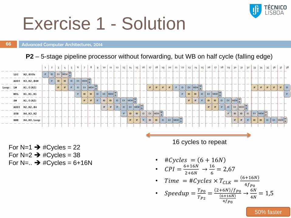
P2 – 5-stage pipeline processor without forwarding, but WB on half cycle (falling edge)
• #𝐶𝑦𝑐𝑙𝑒𝑠 = 6 + 16𝑁
• 𝐶𝑃𝐼 =6+16𝑁
2+6𝑁 →
16
6= 2,67
• 𝑇𝑖𝑚𝑒 = #𝐶𝑦𝑐𝑙𝑒𝑠 × 𝑇𝐶𝐿𝐾 =6+16𝑁
4𝑓𝑃0
• 𝑆𝑝𝑒𝑒𝑑𝑢𝑝 =𝑇𝑃0
𝑇𝑃2=
2+6𝑁 /𝑓𝑃06+16𝑁
4𝑓𝑃0
→6𝑁
4𝑁= 1,5
16 cycles to repeat For N=1 #Cycles = 22
For N=2 #Cycles = 38
For N=.. #Cycles = 6+16N
50% faster
25 26 27 28 29 30 31 32
LDI R2,800h
MUL R1,R1,R1
SW R1,0(R2)
ADDI R2,R2,#4
BNE R4,R0,Loop
SUB R4,R3,R2
ADDI R3,R2,#4N
Loop:
IF ID EX MEMWB
1 2 3 4 5 6 7 8 9 10 11 12 13 14 15 16
LW R1,0(R2)
IF ID EX MEMWB
ID ID
IF IF IF ID EX MEMWB
IF ID EX MEMWB
ID ID
IF IF IF ID EX MEMWB
ID ID
IF IF IF ID EX MEMWB
IF ID EX MEMWB
ID ID
IF IF IF ID EX MEMWB
ID ID
IF IF IF IF IF ID EX MEMWB
IF ID EX MEMWB
ID ID
IF IF IF ID EX MEMWB
ID ID
IF IF IF ID EX MEMWB
IF ID EX MEMWB
ID ID
IF IF IF ID EX MEMWB
ID ID
17 18 19 20 21 22 23 24 33 34 35 36 37 38
IF IF IF IF IF ID
IF
Advanced Computer Architectures, 2014
Exercise 1 - Solution 67
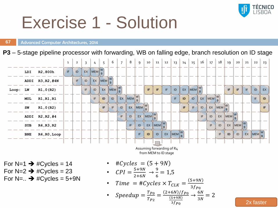
P3 – 5-stage pipeline processor with forwarding, WB on falling edge, branch resolution on ID stage
• #𝐶𝑦𝑐𝑙𝑒𝑠 = 5 + 9𝑁
• 𝐶𝑃𝐼 =5+9𝑁
2+6𝑁 →
9
6= 1,5
• 𝑇𝑖𝑚𝑒 = #𝐶𝑦𝑐𝑙𝑒𝑠 × 𝑇𝐶𝐿𝐾 =5+9𝑁
3𝑓𝑃0
• 𝑆𝑝𝑒𝑒𝑑𝑢𝑝 =𝑇𝑃0
𝑇𝑃2=
2+6𝑁 /𝑓𝑃05+9𝑁
3𝑓𝑃0
→6𝑁
3𝑁= 2
For N=1 #Cycles = 14
For N=2 #Cycles = 23
For N=.. #Cycles = 5+9N
2x faster
LDI R2,800h
MUL R1,R1,R1
SW R1,0(R2)
ADDI R2,R2,#4
BNE R4,R0,Loop
SUB R4,R3,R2
ADDI R3,R2,#4N
Loop:
IF ID EX MEMWB
1 2 3 4 5 6 7 8 9 10 11 12 13 14 15 16
LW R1,0(R2)
IF
17 18 19 20 21 22 23
ID EX MEMWB
IF ID EX MEMWB
IF ID EX MEMWB
ID
IF IF ID EX MEMWB
IF ID EX MEMWB
IF ID EX MEMWB
IF ID EX MEMWB
ID
IF IF IF
Assuming forwarding of R4 from MEM to ID stage
ID EX MEMWB
IF ID EX MEMWB
ID
IF IF ID EX MEMWB
IF ID EX MEMWB
IF ID EX MEMWB
IF ID EX MEMWB
ID
IF IF IF ID EX
IF ID
IF

Advanced Computer Architectures, 2014
Exercise 1 - Solution 68
P4 – 5-stage pipeline processor with forwarding, WB on falling edge and branch predict not taken (with resolution on EX stage)
• #𝐶𝑦𝑐𝑙𝑒𝑠 = 6 + 8𝑁
• 𝐶𝑃𝐼 =6+8𝑁
2+6𝑁 →
8
6= 1,33
• 𝑇𝑖𝑚𝑒 = #𝐶𝑦𝑐𝑙𝑒𝑠 × 𝑇𝐶𝐿𝐾 =6+8𝑁
3.5𝑓𝑃0
• 𝑆𝑝𝑒𝑒𝑑𝑢𝑝 =𝑇𝑃0
𝑇𝑃2=
2+6𝑁 /𝑓𝑃06+8𝑁
3.5𝑓𝑃0
→6𝑁
8𝑁× 3.5 = 2.625
For N=1 #Cycles = 14
For N=2 #Cycles = 22
For N=.. #Cycles = 6+8N
2.6x faster
LDI R2,800h
MUL R1,R1,R1
SW R1,0(R2)
ADDI R2,R2,#4
BNE R4,R0,Loop
SUB R4,R3,R2
ADDI R3,R2,#4N
Loop:
IF ID EX MEMWB
1 2 3 4 5 6 7 8 9 10 11 12 13 14 15 16
LW R1,0(R2)
IF
17 18 19 20 21 22 23
ID EX MEMWB
IF ID EX MEMWB
IF ID EX MEMWB
ID
IF IF ID EX MEMWB
IF ID EX MEMWB
IF ID EX MEMWB
IF ID EX MEMWB
IF ID EX MEMWB
IF ID EX MEMWB
ID
IF IF ID EX MEMWB
IF ID EX MEMWB
IF ID EX MEMWB
IF ID EX MEMWB
IF ID EX
IF ID
IF
(???) IF ID
IF
IF ID
IF
Instruction discarted
Instruction discarted
Instruction discarted
Instruction discarted(???)
Advanced Computer Architectures, 2014
Exercise 2 69
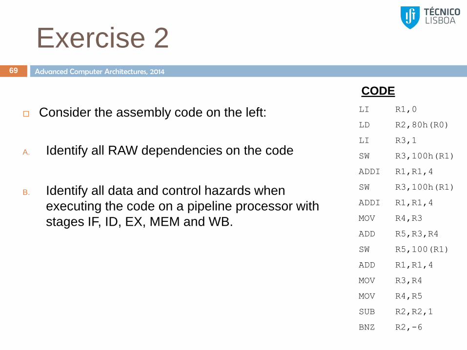
Consider the assembly code on the left:
A. Identify all RAW dependencies on the code
B. Identify all data and control hazards when
executing the code on a pipeline processor with
stages IF, ID, EX, MEM and WB.
LI R1,0
LD R2,80h(R0)
LI R3,1
SW R3,100h(R1)
ADDI R1,R1,4
SW R3,100h(R1)
ADDI R1,R1,4
MOV R4,R3
ADD R5,R3,R4
SW R5,100(R1)
ADD R1,R1,4
MOV R3,R4
MOV R4,R5
SUB R2,R2,1
BNZ R2,-6
CODE

Advanced Computer Architectures, 2014
Exercise 3 70
Consider the execution of the assembly code in the following architectures:
P0 – single cycle processor
P1 – 5-stage multi-cycle processor
P2 – 5-stage pipeline processor without forwarding (WB on falling edge)
P3 – 5-stage pipeline processor with forwarding (WB on falling edge) and branch predict not taken
A. Compute the number of cycles that each processor takes to execute the assembly code.
B. Compute the CPI for each processor.
C. Compute the speed-up of processors P1, P2 and P3 regarding P0, by considering that:
𝑓𝑃1 = 𝑓𝑃2 = 1
.1 𝑓𝑃3 = 4𝑓𝑃0
LI R1,0
LD R2,80h(R0)
LI R3,1
SW R3,100h(R1)
ADDI R1,R1,4
SW R3,100h(R1)
ADDI R1,R1,4
MOV R4,R3
ADD R5,R3,R4
SW R5,100(R1)
ADD R1,R1,4
MOV R3,R4
MOV R4,R5
SUB R2,R2,1
BNZ R2,-6
CODE

Advanced Computer Architectures, 2014
Exercise 4 71
Consider the implementation of the previous
program in a processor P4 with delayed branches
(2 delay slots).
A. Change the assembly code in order to take
maximum advantage of the 2 delay slots
B. Compute the speed-up regarding processor P0
considering that
𝑓𝑃4 = 3.8
𝑓𝑃0
LI R1,0
LD R2,80h(R0)
LI R3,1
SW R3,100h(R1)
ADDI R1,R1,4
SW R3,100h(R1)
ADDI R1,R1,4
MOV R4,R3
ADD R5,R3,R4
SW R5,100(R1)
ADD R1,R1,4
MOV R3,R4
MOV R4,R5
SUB R2,R2,1
BNZ R2,-6
CODE

Advanced Computer Architectures, 2014
Exercise 5 72
Fill the table on the right with
the instruction latencies
considering that:
ALU, FP Add and INT/FP
Multiply execute in
pipeline with 1, 4 and 7
stages, respectively
Division is non-pipelined
and takes 20/30 cycles for
integer/FP operands
Registers R0-R31 are used
only for integer numbers;
FP numbers are stored in
register F0-F31
The processor supports
forwarding to the beginning
of the EX stage; operands
can be forwarded from
stages A4 and M7, before
the result is normalized to
the standard IEEE format
ID
EX
ALU
Integer addition, address calculation and logic operations
FP Adder
Integer/FP Multiply
A4A1 A2 A3
M1 M2 M3 M4 M5 M6 M7
IF WBMEM
Dn
Integer/FP Division
Producing
instruction
Consuming instruction
INT ALU Store FP ADD INT/FP Mult INT/FP Div
INT ALU
Load
FP ADD
INT/FP Mult
INT/FP Div
Advanced Computer Architectures, 2014
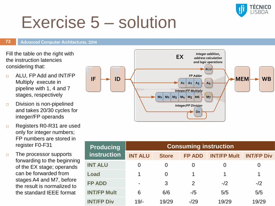
Exercise 5 – solution 73
Fill the table on the right with
the instruction latencies
considering that:
ALU, FP Add and INT/FP
Multiply execute in
pipeline with 1, 4 and 7
stages, respectively
Division is non-pipelined
and takes 20/30 cycles for
integer/FP operands
Registers R0-R31 are used
only for integer numbers;
FP numbers are stored in
register F0-F31
The processor supports
forwarding to the beginning
of the EX stage; operands
can be forwarded from
stages A4 and M7, before
the result is normalized to
the standard IEEE format
ID
EX
ALU
Integer addition, address calculation and logic operations
FP Adder
Integer/FP Multiply
A4A1 A2 A3
M1 M2 M3 M4 M5 M6 M7
IF WBMEM
Dn
Integer/FP Division
Producing
instruction
Consuming instruction
INT ALU Store FP ADD INT/FP Mult INT/FP Div
INT ALU 0 0 0 0 0
Load 1 0 1 1 1
FP ADD - 3 2 -/2 -/2
INT/FP Mult 6 6/6 -/5 5/5 5/5
INT/FP Div 19/- 19/29 -/29 19/29 19/29

Advanced Computer Architectures, 2014
Exercise 6 74
Consider a program with the following characteristics:
• N instructions, of which – 2% are unconditional branches
– 5% are conditional branches, of which • 75% are taken
– 20%, 15% and 10% of instructions have a dependency to the last, second-to-last and third-to-last instructions, respectively
1. How many cycles does the program take
to run in a 5-stage pipeline processor
(IF,ID,EX,MEM,WB) with no conflict
resolution mechanism (other than stalls)
2. What is the speed-up achieved by
implementing data forwarding assuming
that the frequency decreases by 10%.
3. What is the speed-up achieved by
implementing data forwarding and
static branch-prediction assuming that
the frequency decreases by 10%.
1. Assume Branch Predict Taken
2. Assume Branch Predict Not Taken