lesson 4 - ctqp home page level 2/student lesson...• engineer must approve borrow pit before using...
TRANSCRIPT
Student Manual Lesson 4 ‐ Specifications
Version 1.0 1/15 4‐1
Lesson 4
4-1
2015 STANDARD SPECIFICATIONS
STANDARD SPECIFICATIONS FORROAD AND BRIDGE CONSTRUCTION
(SSRBC)
Student Manual Lesson 4 ‐ Specifications
Version 1.0 1/15 4‐2
Governing Order of Documents
Clearing & Grubbing
Overview of the Acceptance Program
Excavation & Embankment
Pipe & Structure Backfill
Geosynthetic Reinforcement
Stabilizing
Base
Retaining Wall Systems
Design Standards
4-2
Items Covered

Student Manual Lesson 4 ‐ Specifications
Version 1.0 1/15 4‐3
• Special Provisions – Specific clauses adding to or revising the Standard Specification,setting forth conditions varying from or additional to the Standard Specifications, for aspecific project.
• Technical Special Provisions – Specifications prepared, signed and sealed by anEngineer registered in the State of Florida other than the State Specifications Engineer,or his designee, which are made part of the Contract as an attachment to theSpecifications Package.
• Plans – The approved plans, including reproductions thereof, showing the location,character, dimensions and details of the work to be done.
• Road & Structures Standards – Some sheets in the Plans are “standard” sheets that arenot designed specifically for this individual project. An example of this type of sheet is thePile Sheet Index Drawing 600.
• Developmental Standards – A specification developed around a new process, procedure,or material and designated as a developmental specification.
• Supplemental Specifications – Approved additions and revisions to the StandardSpecifications.
• Standard Specifications – The directions, provisions and requirements contained herein,together with all stipulations contained in the plans or in the contract documents, settingout or relating to the method and manner of performing the work, or to the quantities andqualities of materials and labor to be furnished under the contract.
Contact the Project Administrator for any clarifications or interpretations
4-3
Governing Order of Documents
Standard Specifications
Supplemental Specifications
Developmental Specifications
Design Standards
Plans (including revisions)
TechnicalSpecial Provisions
SpecialProvisions
Contact the Project Administrator for any clarifications or interpretations
4-3
Governing Order of Documents
Standard Specifications
Supplemental Specifications
Developmental Specifications
Design Standards
Plans (including revisions)
TechnicalSpecial Provisions
SpecialProvisions

Student Manual Lesson 4 ‐ Specifications
Version 1.0 1/15 4‐5
4-4
Clearing & Grubbing

Student Manual Lesson 4 ‐ Specifications
Version 1.0 1/15 4‐6
• Describe the areas typically requiring Clearing & Grubbing
• Interpret significant inspector-related issues in SSRBC
• Describe depths for root removal and plowing
4-5
Learning Outcomes

Student Manual Lesson 4 ‐ Specifications
Version 1.0 1/15 4‐7
4-6
Clearing and Grubbing

Student Manual Lesson 4 ‐ Specifications
Version 1.0 1/15 4‐8
110-2 Standard Clearing and Grubbing
110-2.1 Work Included: Completely remove anddispose of all buildings, timber, brush, stumps, roots,rubbish, debris, and all other obstructions resting onor protruding through the surface of the existingground and the surface of excavated areas, and allother structures and obstructions necessary to beremoved and for which other items of the Contract donot specify the removal thereof, including septictanks, building foundations, and pipes…..
4-7
Section 110- Clearing & Grubbing

Student Manual Lesson 4 ‐ Specifications
Version 1.0 1/15 4‐9
4-8
110-2.1 Work Included (Continued)
…..Perform Standard Clearing and Grubbing within thefollowing areas:(a) All areas where excavation is to be done, includingborrow pits, lateral ditches, right-of-way ditches, etc.(b) All areas where roadway embankments will beconstructed.(c) All areas where structures will be constructed, includingpipe culverts and other pipe lines.
Section 110- Clearing & Grubbing
• Excavation Area• Embankment Area• Area Receiving Structures• Other Areas as Specified

Student Manual Lesson 4 ‐ Specifications
Version 1.0 1/15 4‐10
Pavement/Embankment Area
• 12 inches below ground
• After removal, plow for 6 inches
• Remove all stumps within right-of-way
Borrow Pits
• Cut off all stumps, roots, etc., below finished excavatedsurface
• No clearing and grubbing within 3 feet of right-of-way
110-2.2 Depths of Removal of Roots, Stumps, and Other Debris
4-9
Section 110- Clearing & Grubbing
Student Manual Lesson 4 ‐ Specifications
Version 1.0 1/15 4‐11
4-10
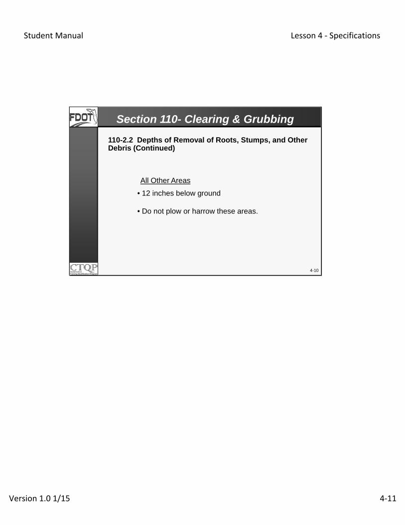
110-2.2 Depths of Removal of Roots, Stumps, and Other Debris (Continued)
• 12 inches below ground
• Do not plow or harrow these areas.
All Other Areas
Section 110- Clearing & Grubbing

Student Manual Lesson 4 ‐ Specifications
Version 1.0 1/15 4‐12
Initial Equipment Comparison
Lot definitions
Initial Production LOT
Density over 105%
Flowchart for Density testing
Sampling & Testing
4-11
Acceptance Program

Student Manual Lesson 4 ‐ Specifications
Version 1.0 1/15 4‐13
• Perform comparison test using all QC, Verification, and IAgauges anticipated to be used
• Do Not perform comparison more than once per project,unless instructed by the Engineer
• Ensure the differences in dry density are within:• 2 PCF between gauges from the same manufacturer• 3 PCF between gauges from different manufacturers
• Perform comparison using QC and Verification gaugeswhen new or repaired gauge is brought to the project
4-12
Acceptance Program
Initial Equipment Comparison
Student Manual Lesson 4 ‐ Specifications
Version 1.0 1/15 4‐14
4-13
Acceptance Program
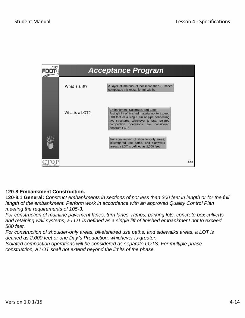
What is a lift?
What is a LOT?
A layer of material of not more than 6 inchescompacted thickness, for full width.
Embankment, Subgrade, and Base:A single lift of finished material not to exceed500 feet or a single run of pipe connectingtwo structures, whichever is less. Isolatedcompaction operations are consideredseparate LOTs.
For construction of shoulder-only areas,bike/shared use paths, and sidewalksareas, a LOT is defined as 2,000 feet.
120-8 Embankment Construction. 120-8.1 General: Construct embankments in sections of not less than 300 feet in length or for the full length of the embankment. Perform work in accordance with an approved Quality Control Plan meeting the requirements of 105-3. For construction of mainline pavement lanes, turn lanes, ramps, parking lots, concrete box culverts and retaining wall systems, a LOT is defined as a single lift of finished embankment not to exceed 500 feet. For construction of shoulder-only areas, bike/shared use paths, and sidewalks areas, a LOT is defined as 2,000 feet or one Day’s Production, whichever is greater. Isolated compaction operations will be considered as separate LOTS. For multiple phase construction, a LOT shall not extend beyond the limits of the phase.

Student Manual Lesson 4 ‐ Specifications
Version 1.0 1/15 4‐15
• A control section consisting of one full LOT isprepared for each type of construction
• The Engineer is notified at least 24 hours prior
• After QC test passes spec., Verification test (VT)is performed
4-14
Acceptance Program
Initial Production LOT

Student Manual Lesson 4 ‐ Specifications
Version 1.0 1/15 4‐16
• No other LOTs are to be prepared until the approval is given
• The Engineer will notify the Contractor within 3 working daysafter receiving Contractor’s QC data
• QC & VT tests must meet the following criteria:• QC test meets spec.• VT meets spec.• Difference between computed dry densities - 2 PCF forsame manufacturer and 3 PCF for different manufacturers
4-15
Acceptance Program
Initial Production LOT

Student Manual Lesson 4 ‐ Specifications
Version 1.0 1/15 4‐17
• If VT fails density, Contractor is to correct the areas ofnon-compliance
• After 3 failing VT, Engineer shall reject the Contractor’sQC Plan
4-16
Acceptance Program
Initial Production LOT

Student Manual Lesson 4 ‐ Specifications
Version 1.0 1/15 4‐18
• The Engineer will perform an Independent Verification(IV) density test within 5 ft.
• If IV test exceeds 105%, the Engineer will initiate anInvestigation
• Investigate the Compaction Methods
• Examine the applicable Maximum Density
• Examine the Material Description
• The Engineer may take an IV Proctor Sample
4-17
Acceptance Program
Density Over 105%

Student Manual Lesson 4 ‐ Specifications
Version 1.0 1/15 4‐19
Test locations (Stations and offsets) are determined using a random number generator approved by the Engineer
Perform new gauge comparison; Retest & re-verify the LOTs
Retest pass?
Eng. accepts 4 LOTs
Did VT meet min. req’ts?
Dept. (VT) tests 1 per 4 LOTs
YES
NO Contractor performs retest within 5’ of VT
Retest compare w/ VT?
YES
NO
YES
Contractor reworks & retest LOT; Eng. will re-verify.
Contractor (QC) tests 1 per LOT
As listed in Specifications
NO
4-18
Acceptance ProgramDensity Testing (Typical)
Mention that frequencies, comparison criteria, and resolution testing for Quality Control and Verification testing will be discussed later in this course
Student Manual Lesson 4 ‐ Specifications
Version 1.0 1/15 4‐20
4-19
Acceptance Program
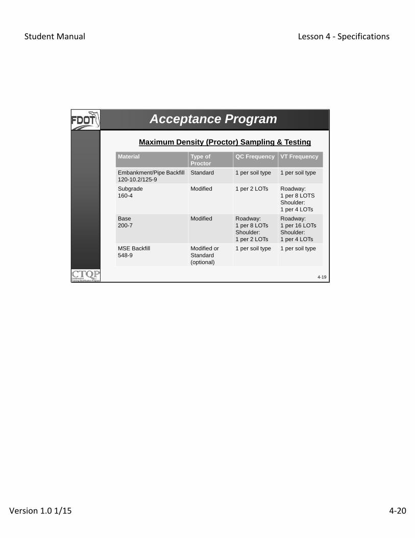
Maximum Density (Proctor) Sampling & Testing
Material Type of Proctor
QC Frequency VT Frequency
Embankment/Pipe Backfill120-10.2/125-9
Standard 1 per soil type 1 per soil type
Subgrade160-4
Modified 1 per 2 LOTs Roadway:1 per 8 LOTSShoulder:1 per 4 LOTs
Base200-7
Modified Roadway:1 per 8 LOTsShoulder:1 per 2 LOTs
Roadway:1 per 16 LOTsShoulder:1 per 4 LOTs
MSE Backfill548-9
Modified or Standard(optional)
1 per soil type 1 per soil type

Student Manual Lesson 4 ‐ Specifications
Version 1.0 1/15 4‐21
4-20
The project plans are superseded by which contract documents?
Roots in the pavement/embankment are to be removed to a depth of _______.
Knowledge Review

Student Manual Lesson 4 ‐ Specifications
Version 1.0 1/15 4‐22
4-21
For gauges of the same manufacturer, thecomparison criteria is that the dry density resultscompare within _______ PCF.
Initial equipment comparison is not to beperformed more than __________ per project,unless instructed by the engineer.
Knowledge Review

Student Manual Lesson 4 ‐ Specifications
Version 1.0 1/15 4‐23
4-22
What is a “Lift”?
The verification comparison criteria for Maximum Density (Proctor) is ____________.
Knowledge Review

Student Manual Lesson 4 ‐ Specifications
Version 1.0 1/15 4‐24
4-23
Excavation & Embankment

Student Manual Lesson 4 ‐ Specifications
Version 1.0 1/15 4‐25
• Describe the various types of excavations
• Describe soils by classification used in embankmentconstruction
• Describe embankment fill placement and compaction
• Describe required earthwork testing processes andfrequencies
• Interpret significant inspector-related issues in SSRBC
4-24
Learning Outcomes
Student Manual Lesson 4 ‐ Specifications
Version 1.0 1/15 4‐26
4-25
Excavation & Embankment

Student Manual Lesson 4 ‐ Specifications
Version 1.0 1/15 4‐27
EXCAVATION
• Regular Excavation
• Roadway
• Borrow
• Subsoil Excavation
• Lateral Ditch
• Channel
EMBANKMENT
• Material
• Construction
• Sampling & Testing
4-26
Section 120- Excavation & Embankment
Excavation and Embankment

Student Manual Lesson 4 ‐ Specifications
Version 1.0 1/15 4‐28
4-27
Section 120- Excavation & Embankment
120-2 Classifications of Excavation.120-2.1 General:
• Regular Excavation
• Subsoil Excavation
• Lateral Ditch Excavation
• Channel Excavation

Student Manual Lesson 4 ‐ Specifications
Version 1.0 1/15 4‐29
120-2.2.2 Borrow Excavation
Consists of the excavation and the utilization ofmaterial from authorized borrow pits, includingonly material that is suitable for the construction ofroadway embankments.
4-28
120-2.2.1 Roadway Excavation
Consists of the excavation and the utilization ordisposal of all material necessary for constructionof the roadway, ditches, channel changes, etc.
Section 120- Excavation & Embankment
Regular Excavation
Student Manual Lesson 4 ‐ Specifications
Version 1.0 1/15 4‐30
120-6 Borrow
• Engineer must approve borrow pit before using
• To obtain approval, contractor must follow theprocedure in Section 120-6
4-29
Section 120- Excavation & Embankment

Student Manual Lesson 4 ‐ Specifications
Version 1.0 1/15 4‐31
120-2.3 Subsoil Excavation
Subsoil Excavation consists of the excavation anddisposal of muck, clay, rock, or any other materialthat is unsuitable in its original position and that isexcavated below the finished grading template…..
4-30
Section 120- Excavation & Embankment
Subsoil Excavation

Student Manual Lesson 4 ‐ Specifications
Version 1.0 1/15 4‐32
Subsoil Excavation: 120-4.1, 5.2, 9.2.3
• To be excavated per plans or per Engineer.
• When approved by the Engineer, muck can be placed onthe slopes
• When plastic material removed, if A-4, A-5, A-6, A-7 soilsremain, compact with sheepsfoot roller
-250 psi pressure
- Feet penetrate less than 1 inch
4-31
Section 120- Excavation & Embankment

Student Manual Lesson 4 ‐ Specifications
Version 1.0 1/15 4‐33
Limits of Subsoil Excavation: Design Standard 500
Organic Material:
• For full width within 1:2 control line
• For full median width up to 64 feet
• Including overlying material
• For full depth
Plastic Material:
• For full width within 1:2 control line
• Up to 2 feet below bottom of base or up to bottom ofditch
4-32
Section 120- Excavation & Embankment
When the median width is greater than 64 feet organic removal will be set by the one to two control line.
Student Manual Lesson 4 ‐ Specifications
Version 1.0 1/15 4‐34
4-33
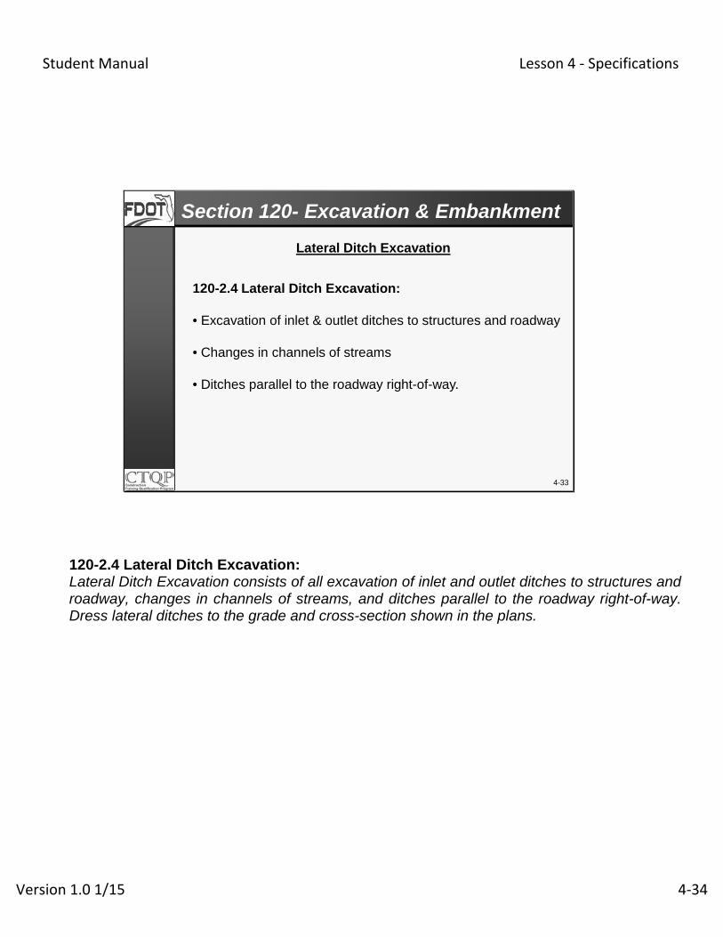
120-2.4 Lateral Ditch Excavation:
• Excavation of inlet & outlet ditches to structures and roadway
• Changes in channels of streams
• Ditches parallel to the roadway right-of-way.
Section 120- Excavation & Embankment
Lateral Ditch Excavation
120-2.4 Lateral Ditch Excavation: Lateral Ditch Excavation consists of all excavation of inlet and outlet ditches to structures and roadway, changes in channels of streams, and ditches parallel to the roadway right-of-way. Dress lateral ditches to the grade and cross-section shown in the plans.

Student Manual Lesson 4 ‐ Specifications
Version 1.0 1/15 4‐35
4-34
120-2.5 Channel Excavation:
Channel Excavation consists of the excavation andsatisfactory disposal of all materials from the limits of thechannel as shown in the plans.
Section 120- Excavation & Embankment
Channel Ditch Excavation
120-2.5 Channel Excavation: Channel Excavation consists of the excavation and satisfactory disposal of all materials from the limits of the channel as shown in the plans.

Student Manual Lesson 4 ‐ Specifications
Version 1.0 1/15 4‐36
120-7 Materials for Embankment
• Contractor responsible for determining suitabilityof excavated material
• Can include broken concrete pavement/rubble,but shall be free of muck, stumps, etc.
4-35
Section 120- Excavation & Embankment
Materials for Embankment

Student Manual Lesson 4 ‐ Specifications
Version 1.0 1/15 4‐37
Maximum particle size (in any dimension):
• Top 12”: 3 ½ inches
• 12 to 24”: 6”
• Below 24”: Not to exceed 12” or compacted thickness ofthe layer, whichever is less
• Larger rocks, up to 18”, outside 1:2 slope, per theEngineer
• Adjacent to bridge end bents or abutments: Nothing largerthan 3 ½” within 3 feet of end-bent piling
4-36
Section 120- Excavation & Embankment
120-7 Materials for Embankment

Student Manual Lesson 4 ‐ Specifications
Version 1.0 1/15 4‐38
Embankment UtilizationFlexible Pavement- Design Standard 505, Sheet 1 to 3
Undivided Roadway
4-37
Section 120- Excavation & Embankment
*

Student Manual Lesson 4 ‐ Specifications
Version 1.0 1/15 4‐39
Embankment UtilizationFlexible & Rigid Pavement- Design Standard 505, Sheet 1 to 3
Divided Roadway
4-38
Section 120- Excavation & Embankment
SS S S
SS
S, P S, P, H
SWater level at the time Fill is placed
Bottom of BaseBottom of Base
Type B StabilizationLBR 40
48”*12
”
12”
48”*
Student Manual Lesson 4 ‐ Specifications
Version 1.0 1/15 4‐40
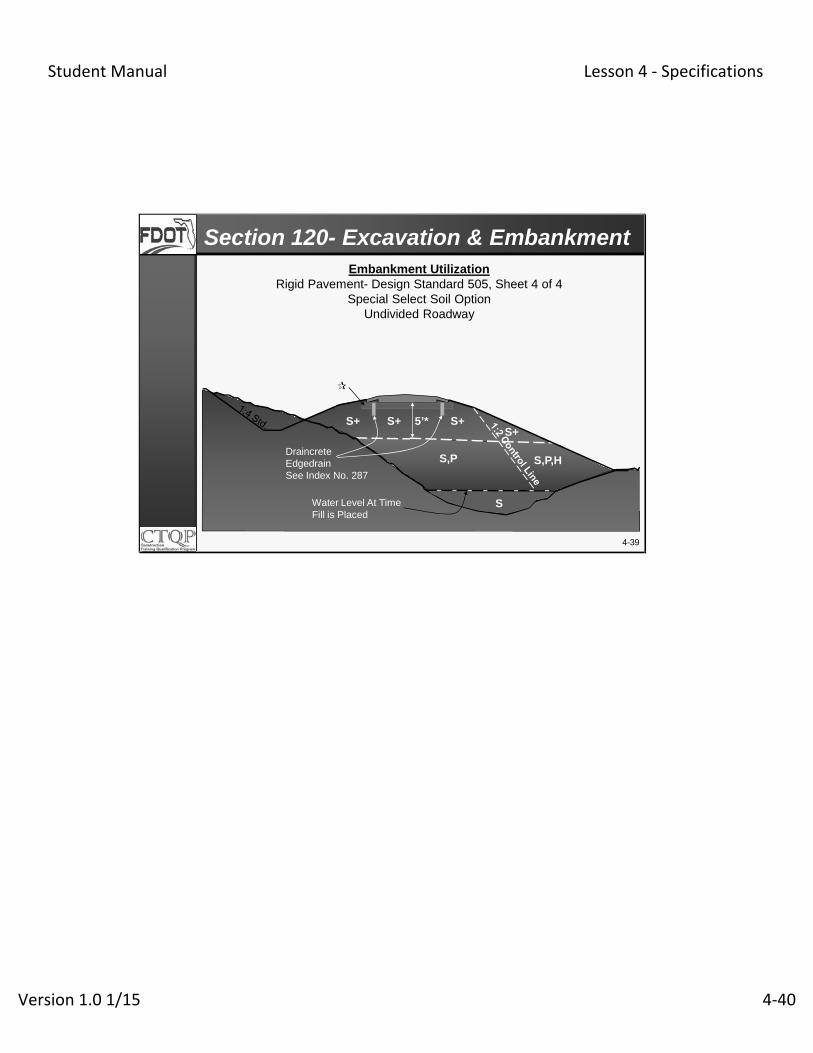
Embankment UtilizationRigid Pavement- Design Standard 505, Sheet 4 of 4
Special Select Soil OptionUndivided Roadway
DraincreteEdgedrainSee Index No. 287
Water Level At TimeFill is Placed
S+
S,P
S+S+ S+
S,P,H
S
5’*
4-39
Section 120- Excavation & Embankment

Student Manual Lesson 4 ‐ Specifications
Version 1.0 1/15 4‐41
4-40
Borrow material must be from an _________.
Highly organic material is to be excavated for the ______________.
Knowledge Review

Student Manual Lesson 4 ‐ Specifications
Version 1.0 1/15 4‐42
4-41
The maximum particle size permitted in the top12 inches of an embankment is ____.
The maximum particle size permitted below 24 inches in the embankment is _____.
Knowledge Review

Student Manual Lesson 4 ‐ Specifications
Version 1.0 1/15 4‐43
4-42
Select material may be used where in the flexiblepavement embankment construction?
Plastic material may be used where in embankment construction?
Knowledge Review

Student Manual Lesson 4 ‐ Specifications
Version 1.0 1/15 4‐44
• Embankment will be constructed in sections of300 feet minimum or full length
• LOT is a single lift of embankment not to exceed500’ for mainline and 2000 feet for shoulder only
• Isolated compaction operations are consideredseparate LOTs
120-8 Embankment Construction
120-8.1 General
4-43
Section 120- Excavation & Embankment

Student Manual Lesson 4 ‐ Specifications
Version 1.0 1/15 4‐45
• For A-3 and A-2-4 with less than 15% passing number 200sieve
-Lifts not more than 12 inches compacted thickness, full width, Last lift to be no more than 6 inches
• For A-1 plastic material with greater than 15% passingnumber 200 sieve
-Construct lifts no more than 6 inch compacted thickness
- 12” Thick lift with test section and Engineer approval
4-44
Section 120- Excavation & Embankment
120-8 Embankment Construction
120-8.2 Dry Fill Method
Student Manual Lesson 4 ‐ Specifications
Version 1.0 1/15 4‐46
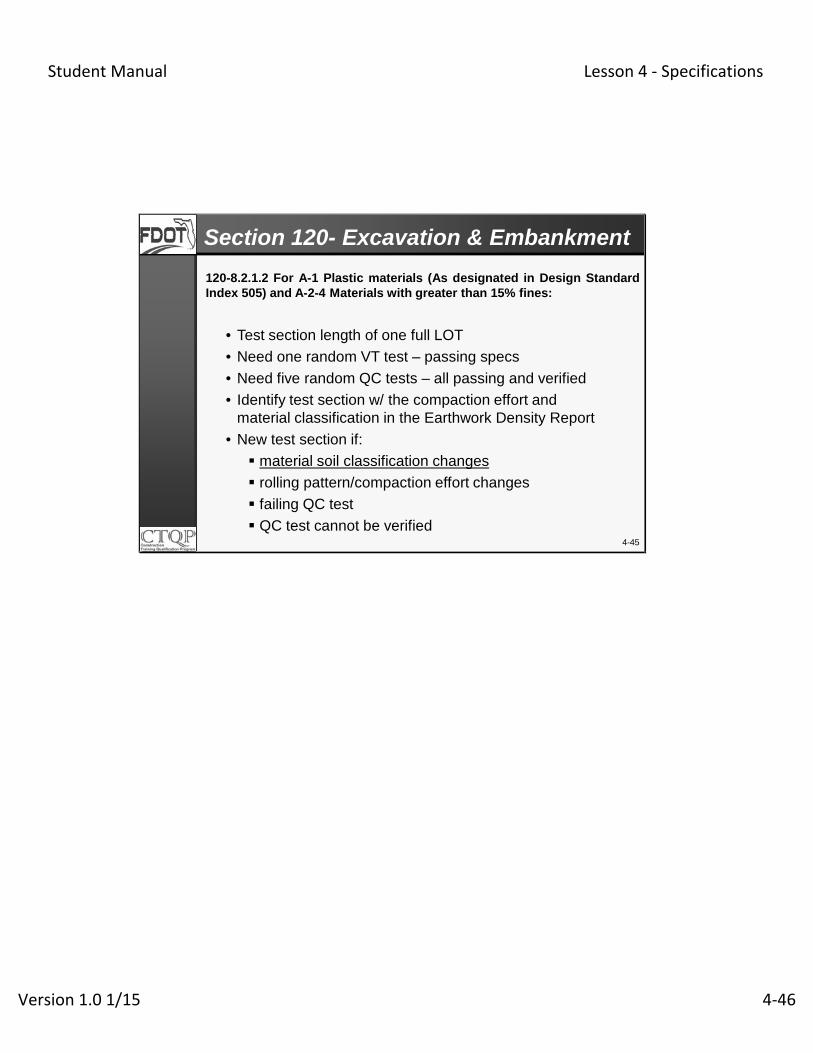
• Test section length of one full LOT
• Need one random VT test – passing specs
• Need five random QC tests – all passing and verified
• Identify test section w/ the compaction effort andmaterial classification in the Earthwork Density Report
• New test section if:
material soil classification changes
rolling pattern/compaction effort changes
failing QC test
QC test cannot be verified4-45
Section 120- Excavation & Embankment
120-8.2.1.2 For A-1 Plastic materials (As designated in Design StandardIndex 505) and A-2-4 Materials with greater than 15% fines:

Student Manual Lesson 4 ‐ Specifications
Version 1.0 1/15 4‐47
…….The Engineer reserves the right to terminateContractor’s use of thick lift construction.Whenever the Engineer determines that theContractor is not achieving satisfactory results,revert to the 6 inch compacted lifts.
Thick Lift Placement (Continued)
4-46
Section 120- Excavation & Embankment
120-8.2.1.2 For A-1 Plastic materials (As designated in Design StandardIndex 505) and A-2-4 Materials with greater than 15% fines:

Student Manual Lesson 4 ‐ Specifications
Version 1.0 1/15 4‐48
4-47
• Not to be used in construction areas that are belowseasonal high ground water table elevation
• Not to be used as MSE Wall backfill
• Not to be placed in the top 3 feet of slopes andshoulders that are grassed or have other type ofvegetation established
• Two acceptable methods of use:
-Soil and RAP mixture
-Alternate Soil and RAP Layer Construction
120-8.4 Reclaimed Asphalt Pavement (RAP) Method
Section 120- Excavation & Embankment
120-8.4 Reclaimed Asphalt Pavement (RAP) Method: 120-8.4.1 General: Use only RAP material: 1) stored at facilities with an approved Florida Department of Environmental Protection Stormwater permit; or, 2) transferred directly from a milling project to the Department project. Certify the source if RAP material is from an identifiable Department project. Do not use RAP material in the following areas: 1) Construction areas that are below the seasonal high groundwater table elevation; or 2)MSE Wall backfill; 3) underneath MSE Walls or 4) The top 6 inches of embankment. Prior to placement, submit documentation to the Engineer for his approval, outlining the proposed location of the RAP material.
Student Manual Lesson 4 ‐ Specifications
Version 1.0 1/15 4‐49
4-48
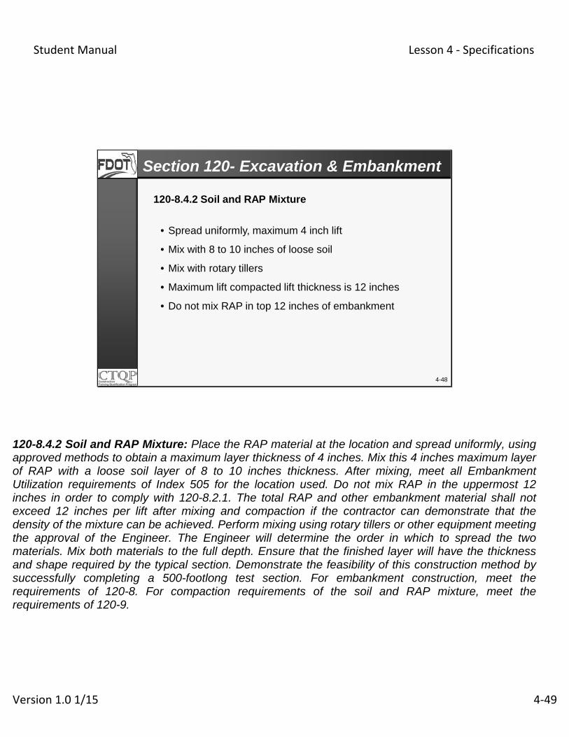
• Spread uniformly, maximum 4 inch lift
• Mix with 8 to 10 inches of loose soil
• Mix with rotary tillers
• Maximum lift compacted lift thickness is 12 inches
• Do not mix RAP in top 12 inches of embankment
120-8.4.2 Soil and RAP Mixture
Section 120- Excavation & Embankment
120-8.4.2 Soil and RAP Mixture: Place the RAP material at the location and spread uniformly, using approved methods to obtain a maximum layer thickness of 4 inches. Mix this 4 inches maximum layer of RAP with a loose soil layer of 8 to 10 inches thickness. After mixing, meet all Embankment Utilization requirements of Index 505 for the location used. Do not mix RAP in the uppermost 12 inches in order to comply with 120-8.2.1. The total RAP and other embankment material shall not exceed 12 inches per lift after mixing and compaction if the contractor can demonstrate that the density of the mixture can be achieved. Perform mixing using rotary tillers or other equipment meeting the approval of the Engineer. The Engineer will determine the order in which to spread the two materials. Mix both materials to the full depth. Ensure that the finished layer will have the thickness and shape required by the typical section. Demonstrate the feasibility of this construction method by successfully completing a 500-footlong test section. For embankment construction, meet the requirements of 120-8. For compaction requirements of the soil and RAP mixture, meet the requirements of 120-9.

Student Manual Lesson 4 ‐ Specifications
Version 1.0 1/15 4‐50
4-49
Section 120- Excavation & Embankment
120-8.4.3 Alternate Soil and RAP Layer Construction
• Construct soil in 6 to 12 inch compacted lifts and RAP inalternate layers with 6 inch maximum compacted lifts
• Use soil with a minimum LBR value of 40
• Must successfully complete a 500 foot test section.
• Compact both soil and RAP, to meet the requirements of120-9.
120-8.4.3 Alternate Soil and RAP Layer Construction: Construct soil in 6 to 12 inches compacted lifts and rap in alternate layers with 6 inches maximum compacted lifts. Use soil with a minimum LBR value of 40 to prevent failure during compaction of the overlying rap layer. Demonstrate the feasibility of this construction method by successfully completing a 500-foot long test section. for compaction requirements of both soil and rap, meet the requirements of 120-9.

Student Manual Lesson 4 ‐ Specifications
Version 1.0 1/15 4‐51
• Uniformly compact each layer
• Over unstable foundation:
-Layer can be greater than 12 inches
-Top 6 inches = 100% Standard Proctor
• Minimum 100% of Standard Proctor within 1:2 slope
4-50
120-9 Compaction Requirements (120-9.2.1, 9.2.2, 10.2)
Section 120- Excavation & Embankment

Student Manual Lesson 4 ‐ Specifications
Version 1.0 1/15 4‐52
No Density Testing Required(120-9.2.2, 9.2.4, 9.2.5, 9.2.6)
• For embankment that is deposited in water
• For embankment that will be incorporatedinto a pavement, base course or stabilizedsubgrade
• For upper 6 inches of areas designated forgrass/plant growth
4-51
Section 120- Excavation & Embankment

Student Manual Lesson 4 ‐ Specifications
Version 1.0 1/15 4‐53
EGL
In general, up to 12” above the water table will become saturated (affected by water) during compaction. Begin density testing on the first lift not affected by water.
4-52
Section 120- Excavation & Embankment
Lifts Affected by Water(120-10.3.1, Table)

Student Manual Lesson 4 ‐ Specifications
Version 1.0 1/15 4‐54
120-9.4 Compaction of Subgrade:
100% of Standard Proctor, both in cuts and fills,where not stabilizing, since subgrade is part of theembankment
No density testing required for narrow wideningstrips or paved shoulders, 5’ feet or less in width
4-53
Section 120- Excavation & Embankment

Student Manual Lesson 4 ‐ Specifications
Version 1.0 1/15 4‐55
The minimum length of embankment to be constructed is _________________.
For a thick lift test section how many QC density tests are taken?
4-54
Knowledge Review

Student Manual Lesson 4 ‐ Specifications
Version 1.0 1/15 4‐56
Density testing is not required for narrow widening strips onundisturbed soil. Narrow widening strips are __________ inwidth?
As a general rule of thumb, when fill is deposited in water,density testing generally begins _____________ above thewater level at the time the fill is placed.
4-55
Knowledge Review

Student Manual Lesson 4 ‐ Specifications
Version 1.0 1/15 4‐57
QC is verified
Did QC & VT compare w/in
4.5 pcf?
Contractor (QC) & Dept. (VT) samples & tests(1 per Soil Type)
YES
NO
VT results will be used
YESQC results will be used
Eng. will take a Resolution Sample
SMO/designee will test Resolution (RT) sample
NO
4-56
Maximum Density (Proctor) (120-10.1, 3, & 4)
Section 120- Excavation & Embankment
Does RT & QC compare w/in
4.5 pcf?

Student Manual Lesson 4 ‐ Specifications
Version 1.0 1/15 4‐58
4-57

Student Manual Lesson 4 ‐ Specifications
Version 1.0 1/15 4‐59
4-58Test locations (Stations and offsets) are determined using a random number generator approved by the Engineer
Perform new gauge comparison; Retest & re-verify the LOTs
Retest pass?
Eng. accepts 4 LOTs
Did VT meet min. req’ts?
Dept. (VT) tests 1 per 4 LOTs
YES
NO Contractor performs retest within 5’ of VT
Retest compare w/ VT?
YES
NO
YES
Contractor reworks & retest LOT; Eng. will re-verify.
Contractor (QC) tests 1 per LOT
As listed in Specifications
NO
Density Testing (120-10.1, 3, 4, &5)
Section 120- Excavation & Embankment
Student Manual Lesson 4 ‐ Specifications
Version 1.0 1/15 4‐60
4-59
Student Manual Lesson 4 ‐ Specifications
Version 1.0 1/15 4‐61
4-60
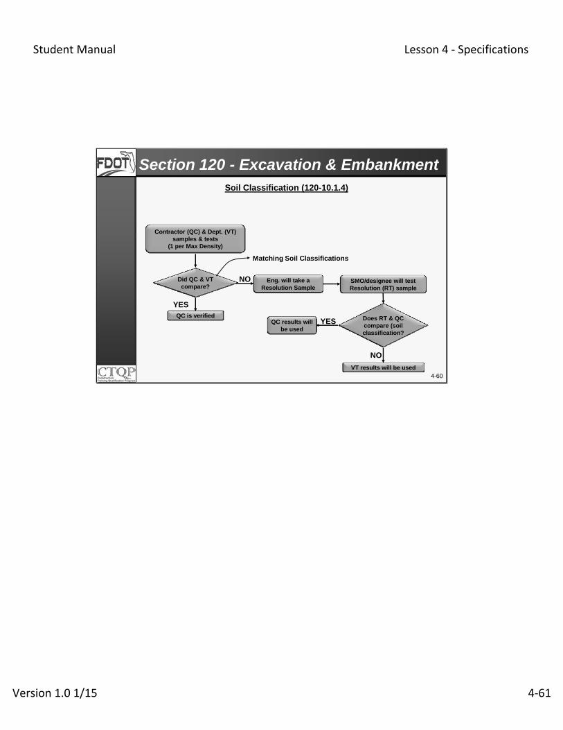
QC is verified
Did QC & VT compare?
Contractor (QC) & Dept. (VT) samples & tests
(1 per Max Density)
YES
NO
VT results will be used
YESQC results will be used
Eng. will take a Resolution Sample
SMO/designee will test Resolution (RT) sample
NO
Soil Classification (120-10.1.4)
Does RT & QC compare (soil classification?
Matching Soil Classifications
Section 120 - Excavation & Embankment

Student Manual Lesson 4 ‐ Specifications
Version 1.0 1/15 4‐62
4-61
Section 120- Excavation & Embankment
120-10.1.5 Department Verification
• The Engineer will select test locations, including Station,Offset, and Lift, using a Random Number generator basedon the Lots under consideration.
• The Engineer may perform additional IndependentVerification (IV) testing.
• IV test results will be used in the same manner asVerification test results.
• Engineer reserves the right to accept the materials andwork through visual inspection for projects requiring less thanfour QC tests per material type.
120-10.1.5 Department Verification: The Engineer will conduct a Verification test(s) in order to accept all materials and work associated with 120-10.1.4. The Engineer will verify the Quality Control results if they meet the Verification Comparison Criteria, otherwise the Engineer will implement Resolution procedures. The Engineer will select test locations, including Station, Offset, and Lift, using a Random Number generator based on the Lots under consideration. Each Verification test evaluates all work represented by the Quality Control testing completed in those LOTs.
In addition to the Verification testing, the Engineer may perform additional Independent Verification (IV) testing. The Engineer will evaluate and act upon the IV test results in the same manner as Verification test results. When the project requires less than four Quality Control tests per material type, the Engineer reserves the right to accept the materials and work through visual inspection.

Student Manual Lesson 4 ‐ Specifications
Version 1.0 1/15 4‐63
4-62
Section 120- Excavation & EmbankmentFrequency (120-10.3.1)
Test NameQuality Control
Verification
Verification of Shoulder-Only Areas,Bike/Shared Paths Paths, and Sidewalks
MaximumDensity(Proctor)
One per soil type
One per soil type One per soil type
Density One per LOT One per four LOTS and for wet conditions, first lift not affected by water
One per two LOTS
Soil Classification
One per Max Density
One per Max Density One per Standard Proctor MaximumDensity

Student Manual Lesson 4 ‐ Specifications
Version 1.0 1/15 4‐64
• The testing frequency will be reduced to one test everytwo LOTs if, for 12 consecutive verified LOTs:
- No Resolution testing was required or
- If required, the QC test data was upheld.
• Identify the LOTs in the Earthwork Record System
• The Engineer will be notified in writing before beginning“reduced frequency”
• If VT fails and QC test data is not upheld, revert tooriginal frequency
• Reduced Frequency Testing is not allowed for 2000 footLOTS
120-10.1.6 Reduced Testing Frequency
4-63
Section 120- Excavation & Embankment

Student Manual Lesson 4 ‐ Specifications
Version 1.0 1/15 4‐65
4-64
Excavation for Pipe & Structures

Student Manual Lesson 4 ‐ Specifications
Version 1.0 1/15 4‐66
• Describe Pipe & Structure excavation and backfilling
requirements
• Identify Pipe & Structure compaction requirements
• Define the backfill Zones for pipe
• Define the sampling & testing required for Pipes &
Structures
• Interpret significant inspector-related issues in SSRBC
4-65
Learning Outcomes

Student Manual Lesson 4 ‐ Specifications
Version 1.0 1/15 4‐67
4-66
Excavation for Pipe & Structures
Student Manual Lesson 4 ‐ Specifications
Version 1.0 1/15 4‐68
• Pipe Trench Excavation
• Pipe and Structure Backfilling
• Compaction Requirements
• Zone Definitions
• Sampling & Testing
4-67
Section 125- Excav. Pipe & Structures

Student Manual Lesson 4 ‐ Specifications
Version 1.0 1/15 4‐69
4-68
125-4.4 Pipe Trench Excavation:
• Remove soil not meeting the specifications to a depth of 4inches below the bottom of the pipe elevation.
• Remove rock, boulders or other hard lumpy or unyieldingmaterial to a depth of 12 inches below the bottom ofthe pipe elevation.
• For pipe lines placed above the natural ground line, placeand compact the embankment, prior to excavation of thetrench, to an elevation at least 2 feet above the top of thepipe and to a width equal to four pipe diameters, and thenexcavate the trench to the required grade.
Section 125- Excav. Pipe & Structures
125-4.4 Pipe Trench Excavation: Excavate trenches for pipe culverts and storm sewers to the elevation of the bottom of the pipe and to a width sufficient to provide adequate working room. Remove soil not meeting the classification specified as suitable backfill material in 125-8.3.2.2, to a depth of 4 inches below the bottom of the pipe elevation. Remove rock, boulders or other hard lumpy or unyielding material to a depth of 12 inches below the bottom of the pipe elevation. Remove muck or other soft material to a depth necessary to establish a firm foundation. Where the soils permit, ensure that the trench sides are vertical up to at least the midpoint of the pipe. For pipe lines placed above the natural ground line, place and compact the embankment, prior to excavation of the trench, to an elevation at least 2 feet above the top of the pipe and to a width equal to four pipe diameters, and then excavate the trench to the required grade. For pipe trenches utilizing trench boxes, ensure that the trench box used is of sufficient width to permit thorough tamping of bedding material under and around the pipes as specified in 125-8.1.6. Do not disturb the installed pipe and its embedment when moving trench boxes. Move the trench box carefully to avoid excavated wall displacement or damage. As the trench box is moved, fill any voids
Student Manual Lesson 4 ‐ Specifications
Version 1.0 1/15 4‐70
left by the trench box and continuously place and compact the backfill material adjacent to and all along the side of the trench box walls to fill any voids created by the trench box.

Student Manual Lesson 4 ‐ Specifications
Version 1.0 1/15 4‐71
125-4.4 Pipe Trench Excavation
Place and compact the embankment prior to excavation of the trench
4-69
Section 125- Excav. Pipe & Structures

Student Manual Lesson 4 ‐ Specifications
Version 1.0 1/15 4‐72
4-70
125-8 Backfilling.125-8.1 General Requirements for Structures and Pipe:125-8.1.1 General:
• A LOT is defined as one lift of backfill material placement,not to exceed 500 feet in length or a single run of pipeconnecting two successive structures, whichever is less.
• Backfill for structures and pipe compacted in one operationwill be considered as one LOT within the cover zone.
• Backfill around structures compacted separately from thepipe will be considered as separate lots.
Section 125- Excav. Pipe & Structures
125-8 Backfilling. 125-8.1 General Requirements for Structures and Pipe: 125-8.1.1 General: Backfill in the dry whenever normal dewatering equipment and methods can accomplish the needed dewatering. A LOT is defined as one lift of backfill material placement, not to exceed 500 feet in length or a single run of pipe connecting two successive structures, whichever is less. Backfill for structures and pipe compacted in one operation will be considered as one LOT within the cover zone. Backfill around structures compacted separately from the pipe will be considered as separate LOTs. Backfill on each side of the pipe for the first lift will be considered a separate LOT. Backfill on opposite sides of the pipe for the remaining lifts will be considered separate LOTs, unless the same compactive effort is applied. Same compactive effort is defined as the same type of equipment (make and model) making the same number of passes on both sides of the pipe. For multiple phase backfill, a LOT shall not extend beyond the limits of the phase. When placing backfill within trench box each lift of backfill is considered a LOT. Placement of backfill within trench box limits will be considered a complete operation before trench box is moved for next backfill operation. When the trench box is moved for next backfill operation this will start new LOTs for each lift. Follow the density testing frequency in 125-9.3.1

Student Manual Lesson 4 ‐ Specifications
Version 1.0 1/15 4‐73

Student Manual Lesson 4 ‐ Specifications
Version 1.0 1/15 4‐74
4-71
125-8 Backfilling.125-8.1 General Requirements for Structures and Pipe:125-8.1.1 General: Continued• Backfill on each side of the pipe for the first lift will be considered a separate LOT.
•Backfill on opposite sides of the pipe for the remaining liftswill be considered separate LOTs, unless the samecompactive effort is applied.
• For multiple phase backfill, a LOT shall not extend beyondthe limits of the phase.
• When placing backfill within trench box each lift of backfill isconsidered a LOT.
Section 125- Excav. Pipe & Structures
125-8 Backfilling. 125-8.1 General Requirements for Structures and Pipe: 125-8.1.1 General: Backfill in the dry whenever normal dewatering equipment and methods can accomplish the needed dewatering. A LOT is defined as one lift of backfill material placement, not to exceed 500 feet in length or a single run of pipe connecting two successive structures, whichever is less. Backfill for structures and pipe compacted in one operation will be considered as one LOT within the cover zone. Backfill around structures compacted separately from the pipe will be considered as separate LOTs. Backfill on each side of the pipe for the first lift will be considered a separate LOT. Backfill on opposite sides of the pipe for the remaining lifts will be considered separate LOTs, unless the same compactive effort is applied. Same compactive effort is defined as the same type of equipment (make and model) making the same number of passes on both sides of the pipe. For multiple phase backfill, a LOT shall not extend beyond the limits of the phase. When placing backfill within trench box each lift of backfill is considered a LOT. Placement of backfill within trench box limits will be considered a complete operation before trench box is moved for next backfill operation. When the trench box is moved for next backfill operation this will start new LOTs for each lift. Follow the density testing frequency in 125-9.3.1.

Student Manual Lesson 4 ‐ Specifications
Version 1.0 1/15 4‐75

Student Manual Lesson 4 ‐ Specifications
Version 1.0 1/15 4‐76
• No more than 12” compacted thickness, outside the soil envelope only
• Test section length of one LOT
• Need five random QC tests – all passing and verified
• Identify test section w/ the compaction effort and material classification in the Earthwork Record System
4-72
Thick Lift Placement-Structures- 125-8.1.6
Section 125- Excav. Pipe & Structures

Student Manual Lesson 4 ‐ Specifications
Version 1.0 1/15 4‐77
New test section if:
• material soil classification changes
• rolling pattern/compaction effort changes
• failing QC test
• QC test cannot be verified
4-73
Thick Lift Placement-Structures- 125-8.1.6
Section 125- Excav. Pipe & Structures

Student Manual Lesson 4 ‐ Specifications
Version 1.0 1/15 4‐78
Placement & Compaction- Structures and Pipe
125-8.1.6, 9.2.1, 9.2.2
INSIDE100% Standard Proctor
OUTSIDEApprox. equal tosoil next to pipetrench, except forcommercial ormultiple residentialdriveways
Compaction
4-74
Section 125- Excav. Pipe & Structures
Pipe
Lifts 6” compactedS
tru
ctu
re
Placement

Student Manual Lesson 4 ‐ Specifications
Version 1.0 1/15 4‐79
Placement & Compaction- Structures
Wet: 125-8.2.1 and 125-8.2.5.
4-75
12” Relatively Dry Material –Compacted by Tamping
Hand Tamp A-3 Only
Placement & Compaction
Density
Mechanical Tamping
Str
uct
ure
Begin Density Testing
Str
uct
ure
Section 125- Excav. Pipe & Structures

Student Manual Lesson 4 ‐ Specifications
Version 1.0 1/15 4‐80
Zone Definitions- 125-8.3.1
Bedding Zone 4” below the pipe
PIPE
Top Zone - Up to the base or final grade
CoverZone
12” above pipe
Lowest ZoneBottom ofTrench
Soi
l En
velo
pe
(No
Thi
ck L
ift)
4-76
Section 125- Excav. Pipe & Structures
Student Manual Lesson 4 ‐ Specifications
Version 1.0 1/15 4‐81
4-77
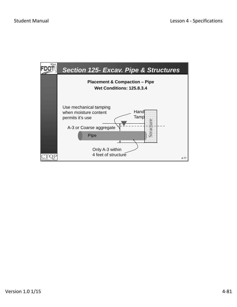
Placement & Compaction – Pipe
Wet Conditions: 125.8.3.4
Section 125- Excav. Pipe & Structures
Use mechanical tamping when moisture content permits it’s use
Hand Tamp
Pipe
A-3 or Coarse aggregate
Only A-3 within 4 feet of structure
Str
uctu
re

Student Manual Lesson 4 ‐ Specifications
Version 1.0 1/15 4‐82
4-78
QC is verified
Did QC & VT compare w/in
4.5 pcf?
Contractor (QC) & Dept. (VT) samples & tests(1 per Soil Type)
YES
NO
VT results will be used
YESQC results will be used
Eng. will take a Resolution Sample
SMO/designee will test Resolution (RT) sample
NO
Maximum Density (Proctor) 125-9 & 10
Does RT & QC compare w/in
4.5 pcf?
Section 125- Excav. Pipe & Structures

Student Manual Lesson 4 ‐ Specifications
Version 1.0 1/15 4‐83
4-79Test locations (Stations and offsets) are determined using a random number generator approved by the Engineer
Perform new gauge comparison; Retest & re-verify the LOTs
Retest pass?
Eng. accepts 4 LOTs
Did VT meet min. req’ts?
Dept. (VT) tests 1 per 4 LOTs
YES
NO Contractor performs retest within 5’ of VT
Retest compare w/ VT?
YES
NO
YES
Contractor reworks & retest LOT; Eng. will re-verify.
Contractor (QC) tests 1 per LOT
As listed in Specifications
NO
Density Testing -125-9 & 10
Section 125- Excav. Pipe & Structures

Student Manual Lesson 4 ‐ Specifications
Version 1.0 1/15 4‐84
Acceptance Criteria (Density Testing)-125-9.2.1
Match Density of Soil in Trench
100% of StandardProctor
4-80
Bedding Zone 4” below the pipe
PIPE
Top Zone - Up to the base or final grade
CoverZone
12” above pipe
Lowest Zone
Section 125- Excav. Pipe & Structures
100% of StandardProctor (RCP)
Cover Zone100% of Standard Proctor when the distance from top of pipe to bottom of base 15 inches or less95% of Standard Proctor when the distance from top of pipe to bottom of base greater than 15 inches
125-9.2 Acceptance Criteria: 125-9.2.1 Density: Obtain a minimum QC density in any LOT of 100% of the Standard Proctor maximum density as determined by AASHTO T 99, Method C, or the requirements of 125-8.3.3.1 when applicable. When the cover height below the bottom of base under asphalt pavement, below concrete pavement, or below unpaved ground, exceeds 15 inches, compact the pipe backfill to a density of a least 95% of the Standard Proctor maximum density as determined by AASHTO T99, Method C. For density requirements around drainage structures, obtain a minimum QC density in any LOT of 100% of the Standard Proctor maximum density as determined by AASHTO T99 for a distance of one pipe diameter but not less than 3 feet from the outside face of the structure. 125-9.2.2 Exceptions to Structures and Pipe Density Requirements: Compact the backfill to a firmness approximately equal to that of the soil next to the pipe trench in locations outside the plane described by a two (horizontal) to one (vertical) slope downward from the roadway shoulder line or the back of curb as applicable. Apply 125-9.2.1 when compacting side-drain pipe backfill under driveways serving a property that is not a single residential lot.

Student Manual Lesson 4 ‐ Specifications
Version 1.0 1/15 4‐85

Student Manual Lesson 4 ‐ Specifications
Version 1.0 1/15 4‐86
Test Name Quality Control Verification
Standard Proctor
Maximum Density One per soil type One per soil type
Density One per LOT
One per four consecutive LOTs and for wet conditions, the first lift not affected by water
Soil ClassificationOne per Standard Proctor Maximum density
One per Standard Proctor Maximum density
4-81
Testing Frequency Review- 125-9.3
Section 125- Excav. Pipe & Structures

Student Manual Lesson 4 ‐ Specifications
Version 1.0 1/15 4‐87
Test locations including Stations and Offsets aredetermined using the Random Number generatorapproved by the Engineer.
The Engineer may perform Independent Verification(IV) testing, which will be used in the same manneras Verification testing (VT).
4-82
Testing Frequency Review
Section 125- Excav. Pipe & Structures

Student Manual Lesson 4 ‐ Specifications
Version 1.0 1/15 4‐88
• No Resolution testing required for 6 consecutiveLOTs
• Reduce the Quality Control density testing to onetest every two Lots or one every four LOTs for trenchbox operations.
• Identify the substantiating tests in the Density LogBook
• Notify the Engineer in writing prior to startingreduced frequency of testing
4-83
Reduce Frequency Testing- 125-9.1.1
Section 125- Excav. Pipe & Structures

Student Manual Lesson 4 ‐ Specifications
Version 1.0 1/15 4‐89
• Generate random numbers based on the two LOTsunder consideration.
• Obtain the Engineer’s approval to place more thanone LOT over an untested LOT
• If the Verification test fails, and Quality Control testdata is not upheld by Resolution testing the QualityControl testing will revert to the original frequency.
4-84
Reduce Frequency Testing- 125-9.1.1 (Continued)
Section 125- Excav. Pipe & Structures

Student Manual Lesson 4 ‐ Specifications
Version 1.0 1/15 4‐90
For pipe lines placed above the natural ground line the embankment should be constructed to a minimum length of __________ prior to excavating the trench.
When placing and compacting backfill around structures in wet conditions, do not permit the use of mechanical tampers and hand tampers are required, ________ material is to be used.
4-85
4 Times the pipe diameter
Only A-3
Knowledge Review

Student Manual Lesson 4 ‐ Specifications
Version 1.0 1/15 4‐91
4-86
The area directly beneath the pipe is referred to as the ____zone.
The density requirement within the Cover Zone when top of pipe is 15 inches below bottom of base is _____.
Bedding Zone
100% of AASHTO T-99
Knowledge Review

Student Manual Lesson 4 ‐ Specifications
Version 1.0 1/15 4‐92
The zone from the bottom of the pipe to 12 inches above the pipe is referred to as the ____________ zone.
Thick lift compaction is not allowed in the ________ zone.
4-87
Cover Zone
Soil Envelope
Knowledge Review
Student Manual Lesson 4 ‐ Specifications
Version 1.0 1/15 4‐93
When the top of the pipe is greater than 15 inches below bottom of base, the cover zone is _________.
The density required in the lowest zone is _________.
4-88
95% of AASHTO T-99
Match density of soil in trench
Knowledge Review

Student Manual Lesson 4 ‐ Specifications
Version 1.0 1/15 4‐94
What is the verification density testing frequency for pipe and structures?
Testing locations are to be determined by __________ approved by ___________.
4-89
Knowledge Review
1 per four LOTs
Random Number Generator, Engineer

Student Manual Lesson 4 ‐ Specifications
Version 1.0 1/15 4‐95
4-90
Section 145- Geosynthetic Reinforcement

Student Manual Lesson 4 ‐ Specifications
Version 1.0 1/15 4‐96
• Describe material requirements
• Interpret significant inspector-related issues in SSRBC
Related to Earthwork
• Describe the initial equipment comparison process of the acceptance program
• Identify related Design Standard sheets
4-91
Learning Outcomes

Student Manual Lesson 4 ‐ Specifications
Version 1.0 1/15 4‐97
4-92
Section 145- Geosynthetic Reinforcement

Student Manual Lesson 4 ‐ Specifications
Version 1.0 1/15 4‐98
145-3.1 Materials
• Listed on Roadway Index 501
• Delivered in unopened packages
• Protect from sunlight per manufacturer recommendations
• Reject if defects, tears, punctures, flaws, deterioration or other damage observed
• May be repaired if approved by Engineer
4-93
Section 145- Geosynthetic Reinforcement
145-3 Materials. 145-3.1 Geosynthetic Materials: Use primary and secondary reinforcing elements consisting of a regular array of tensile elements that have sufficient reinforcement strength to perform the prime functions of reinforcement and which are listed on Design Standards, Index No. 501. Deliver geosynthetic materials (including facing and drainage elements) to the job site in unopened shipping packages labeled with the supplier’s name and product name. During shipping and storage, protect the geosynthetic from physical damage, debris and from temperatures greater than 140ºF. Follow the supplier’s recommendations regarding protection from direct sunlight. At the time of installation, the Engineer will reject the material if it has defects, tears, punctures, flaws, deterioration, or other damage. However, if approved by the Engineer, the Contractor may repair torn or punctured sections by placing a patch over the damaged area. Replace or repair any rejected geosynthetic at no additional expense to the Department.

Student Manual Lesson 4 ‐ Specifications
Version 1.0 1/15 4‐99

Student Manual Lesson 4 ‐ Specifications
Version 1.0 1/15 4‐100
145-3.2 Backfill Materials
• Must submit Certified Test results & Certificate ofCompliance that backfill meets requirements of 145-3.2
• Less than avg. 2% by weight of organic content- Nosingle test >3.0%
• Backfill- Max. PI 6; Max. LL 15
pH 4.5-10 (6-10 when metal pipes or metalitems are imbedded in the backfill)
4-94
Section 145- Geosynthetic Reinforcement
145-3.2 Backfill Materials: Use only free draining backfill material in the reinforced volume as shown in the plans meeting the following gradation limits as determined in accordance with AASHTO T 27 and FM 1-T 011: …… Do not use backfill material containing more than 2.0% by weight of organic material, as determined by FM 1-T 267 and by averaging the test results for three randomly selected samples from each stratum or stockpile of a particular material. Consider the stratum or stockpile unsuitable for construction of the reinforced volume if an individual test value exceeds 3.0%. Use backfill with a maximum plasticity index of six as determined by AASHTO T 90, and a maximum liquid limit of 15 as determined by AASHTO T 89. Use backfill materials with a pH between 4.5 and 10.0. When metal pipes or other metal items are embedded in the backfill, use backfill with a pH between 6.0 and 10.0. Do not use soil cement or lime stabilized backfill unless approved by the Engineer. Submit a copy of certified test results and a certificate of compliance certifying that the fill material meets the above requirements to the Engineer for review and approval prior to delivering the backfill to the site. Use a Department-approved testing laboratory for all testing. Submit an alternate design, prepared in accordance with 145-2, when backfill meeting alternate gradation limits is proposed.

Student Manual Lesson 4 ‐ Specifications
Version 1.0 1/15 4‐101

Student Manual Lesson 4 ‐ Specifications
Version 1.0 1/15 4‐102
145-4.2.1 Reinforced Soil Slopes
• Remove all existing vegetation
• Proof roll, minimum 5 passes, in Presence of Engineer
Vibratory roller > 8 tons
Sheepsfoot roller – at least 250 psi
4-95
Section 145- Geosynthetic Reinforcement
145-4.2 Reinforced Soil Slopes: 145-4.2.1 Preparation: Remove all existing vegetation and all unsuitable foundation materials. Prepare the foundation in accordance with Section 110, except as noted herein. Proof roll the graded area with a vibratory roller weighing a minimum of 8 tons or a sheepsfoot roller, where appropriate, exerting a compression of at least 250 pounds psi on the tamper foot for at least five passes in the presence of the Engineer or as directed by the Engineer. Remove and replace any soft or loose foundation subsoils that are, in the opinion of the Engineer, incapable of sustaining the required proof rolling, in accordance with Section 125. Provide proof rolled ground surfaces which are uniform, smooth, and free of abrupt changes in slope, debris, and irregularities that might damage the reinforcement. Promptly repair and restore to their original condition any areas outside the limits of disturbance shown on the plans which are damaged as part of this work at no expense to the Department. Make every possible effort to avoid such damage.
Student Manual Lesson 4 ‐ Specifications
Version 1.0 1/15 4‐103
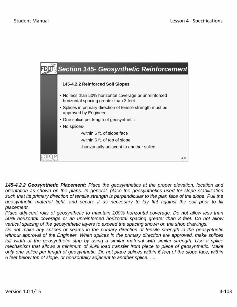
145-4.2.2 Reinforced Soil Slopes
• No less than 50% horizontal coverage or unreinforced horizontal spacing greater than 3 feet
• Splices in primary direction of tensile strength must be approved by Engineer
• One splice per length of geosynthetic
• No splices-
-within 6 ft. of slope face
-within 6 ft. of top of slope
-horizontally adjacent to another splice
4-96
Section 145- Geosynthetic Reinforcement
145-4.2.2 Geosynthetic Placement: Place the geosynthetics at the proper elevation, location and orientation as shown on the plans. In general, place the geosynthetics used for slope stabilization such that its primary direction of tensile strength is perpendicular to the plan face of the slope. Pull the geosynthetic material tight, and secure it as necessary to lay flat against the soil prior to fill placement. Place adjacent rolls of geosynthetic to maintain 100% horizontal coverage. Do not allow less than 50% horizontal coverage or an unreinforced horizontal spacing greater than 3 feet. Do not allow vertical spacing of the geosynthetic layers to exceed the spacing shown on the shop drawings. Do not make any splices or seams in the primary direction of tensile strength in the geosynthetic without approval of the Engineer. When splices in the primary direction are approved, make splices full width of the geosynthetic strip by using a similar material with similar strength. Use a splice mechanism that allows a minimum of 95% load transfer from piece to piece of geosynthetic. Make only one splice per length of geosynthetic. Do not place splices within 6 feet of the slope face, within 6 feet below top of slope, or horizontally adjacent to another splice. …..
Student Manual Lesson 4 ‐ Specifications
Version 1.0 1/15 4‐104
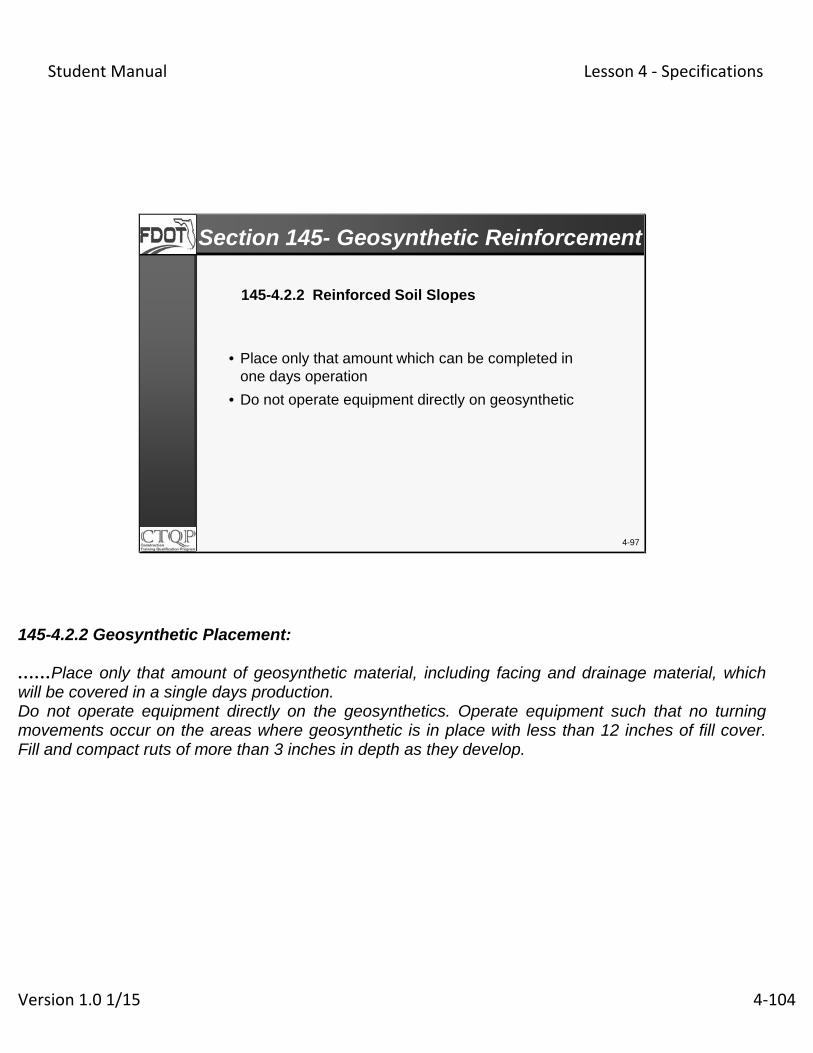
145-4.2.2 Reinforced Soil Slopes
• Place only that amount which can be completed in one days operation
• Do not operate equipment directly on geosynthetic
4-97
Section 145- Geosynthetic Reinforcement
145-4.2.2 Geosynthetic Placement: ……Place only that amount of geosynthetic material, including facing and drainage material, which will be covered in a single days production. Do not operate equipment directly on the geosynthetics. Operate equipment such that no turning movements occur on the areas where geosynthetic is in place with less than 12 inches of fill cover. Fill and compact ruts of more than 3 inches in depth as they develop.

Student Manual Lesson 4 ‐ Specifications
Version 1.0 1/15 4‐105
145-4.2.3 Backfill Placement
• Place Material at 2% on the dry side of optimum
• Do not place wet backfill with moisture content greater than optimum
• Do not stockpile backfill on geosynthetic
• Use smooth wheel rubber tire rollers- No sheepsfoot
• Meet Density requirement- 95% of AASHTO T 180
4-98
Section 145- Geosynthetic Reinforcement
145-4.2.3 Backfill Placement: Maintain uniform moisture content of the backfill material prior to and during compaction throughout each layer of material. Use backfill material having a placement moisture content within 2% on the dry side of optimum. Do not place wet backfill with moisture content greater than optimum in the fill. Spread backfill material over the geosynthetic in the direction of geosynthetic overlaps. Do not stockpile backfill materials on the installed geosynthetics. Avoid construction procedures or equipment which, in the opinion of the Engineer, cause excessive mudwaving. Compact the backfill using either smooth wheel or rubber tire rollers. Do not use sheepsfoot, grid rollers, or other types of equipment employing a foot. At the end of each day’s operation, slope the backfill surface in order to permit runoff of rainwater away from the slope face, or provide some other positive drainage. Place and compact the backfill material in accordance with Section 120 to obtain a density in each soil layer of at least 95% of the maximum density as determined by AASHTO T 180.
Student Manual Lesson 4 ‐ Specifications
Version 1.0 1/15 4‐106
4-99
Section 160- Stabilizing

Student Manual Lesson 4 ‐ Specifications
Version 1.0 1/15 4‐107
• Describe the subgrade stabilization process
• Identify Bearing Value tolerances
• Describe sampling and testing frequencies and requirements
• Verify stabilized subgrade mix depths
4-100
Learning Outcomes
Student Manual Lesson 4 ‐ Specifications
Version 1.0 1/15 4‐108
4-101
Section 160-Stabilizing

Student Manual Lesson 4 ‐ Specifications
Version 1.0 1/15 4‐109
STABILIZED SUBGRADE
• Stabilizing Materials
• Construction Methods
• Sampling & Testing
• Mixing Depth Checks
4-102
Section 160- Stabilizing

Student Manual Lesson 4 ‐ Specifications
Version 1.0 1/15 4‐110
Commercial Material & Local Material• Meet the requirements of Section 914
Existing Base
• Testing is not necessary unless directed by the Engineer
Granular Subbase
• 6 inches of base material may be substituted for 12 inches stabilized subgrade
4-103
Section 160- Stabilizing
160-2, Materials

Student Manual Lesson 4 ‐ Specifications
Version 1.0 1/15 4‐111
Commercial Material
Limerock, shell rock, cemented coquina or shell basesources approved by the Department.
Local Materials
May be soils or recyclable materials such as crushedconcrete, roof tiles and asphalt coated base or reclaimedpavement.
4-104
Section 160- Stabilizing
Stabilizing Material

Student Manual Lesson 4 ‐ Specifications
Version 1.0 1/15 4‐112
Sample local material after spreading and before mixing
97% material must pass the 3-1/2” sieve
LL < 40
PI < 10
Organic Content (Individual sample max. 4%, Max. average 2.5%, minimum of three tests)
4-105
Section 160- Stabilizing
Local Material

Student Manual Lesson 4 ‐ Specifications
Version 1.0 1/15 4‐113
Place embankment material (Subgrade)
Spread high strength materials, if necessary Sample & test stabilizing material
MixCheck depth and homogeneity of mixing Sample & test mixed material
Compact
Grade
STABILIZED SUBGRADE = Subgrade + Stabilization
4-106
Section 160- Stabilizing
160-3, Construction Methods

Student Manual Lesson 4 ‐ Specifications
Version 1.0 1/15 4‐114
After Mixing 97% will pass the 3-1/2 inch (90 mm) sieve LL < 30 and PI < 8 LBR - minimum specifiedNot to exceed depth tolerances Individual – 2 inches LOT-average – 1 inch
After CompactionMinimum density - 98% of Modified Proctor
4-107
Section 160- StabilizingSampling and Testing of Stabilized Subgrade
160-3 & 160-4

Student Manual Lesson 4 ‐ Specifications
Version 1.0 1/15 4‐115
Undertolerances for Bearing Values-160-4.2.1.2
Specified Bearing Value Tolerance
LBR 40 5.0
LBR 35 4.0
LBR 30 (and under) 2.5
Specified Bearing Value
Unsoaked Bearing Value Required
Tolerance
LBR 40 LBR 43 0.0
4-108
Section 160- Stabilizing
Each sample should be split for QC, VT, and RT

Student Manual Lesson 4 ‐ Specifications
Version 1.0 1/15 4‐116
Test locations (Stations and offsets) are determinedusing a random number generator approved by the Engineer
QC is used
Did QC & VT compar w/in
4.5 pcf?
Contractor (QC) collects & tests (1 per 2 LOTs); Each sample is split for VT & RT
YES
NO SMO tests RT sample for that chosen pair of LOTs
Does RT & QC compare w/in 4.5 pcf?
YES NOEng. collects & tests
remaining 3 VT samples- VT results will be used for all 8
LOTS
Eng. (VT) randomly selects one of the 4 split samples (1 per 8 LOTs)
4-109
Stabilizing-Maximum Density (Proctor)160-4
Section 160- Stabilizing
Student Manual Lesson 4 ‐ Specifications
Version 1.0 1/15 4‐117
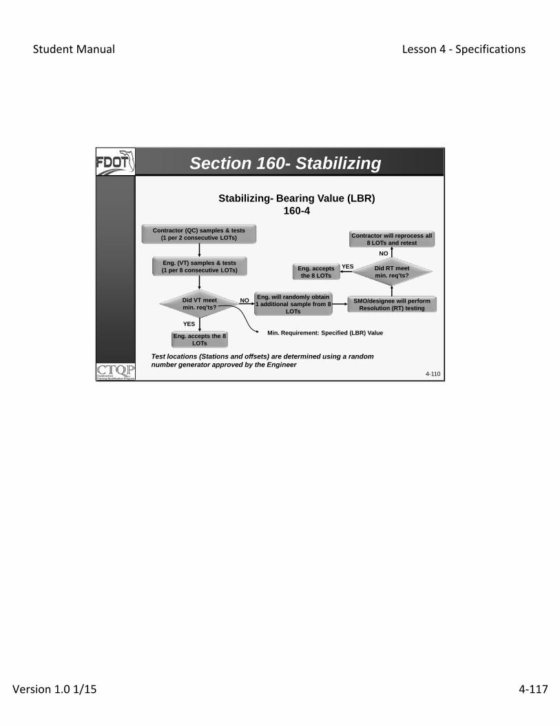
Test locations (Stations and offsets) are determined using a random number generator approved by the Engineer
Eng. accepts the 8 LOTs
Did VT meet min. req’ts?
Contractor (QC) samples & tests(1 per 2 consecutive LOTs)
YES
NOEng. will randomly obtain 1 additional sample from 8
LOTs
Did RT meet min. req’ts?
YES
NO
Contractor will reprocess all 8 LOTs and retest
SMO/designee will perform Resolution (RT) testing
Eng. accepts the 8 LOTs
Eng. (VT) samples & tests(1 per 8 consecutive LOTs)
Min. Requirement: Specified (LBR) Value
4-110
Stabilizing- Bearing Value (LBR)160-4
Section 160- Stabilizing

Student Manual Lesson 4 ‐ Specifications
Version 1.0 1/15 4‐118
4-111
Density Testing- 160-4
Section 160- Stabilizing
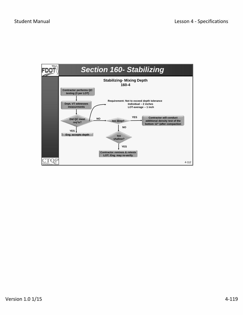
Test locations (Stations and offsets) are determined using a random number generator approved by the Engineer
Perform new gauge comparison; Retest & re-verify the LOTs
Retest pass?
Eng. accepts 4 LOTs
Did VT meet min. req’ts?
Dept. (VT) tests 1 per 4 LOTs
YES
NO Contractor performs retest within 5’ of VT
Retest compare w/ VT?
YES
NO
YES
Contractor reworks & retest LOT; Eng. will re-verify.
Contractor (QC) tests 1 per LOT
As listed in Specifications
NO
Student Manual Lesson 4 ‐ Specifications
Version 1.0 1/15 4‐119
too shallow?
Eng. accepts depth
Did QC meet req’ts?
Dept. VT witnesses measurments
YES
NO
NO
Contractor remixes & retests LOT; Eng. may re-verify.
Contractor will conduct additional density test of the bottom 12” (after compaction
Contractor performs QC testing (3 per LOT)
Requirement: Not to exceed depth toleranceIndividual – 2 inchesLOT-average – 1 inch
4-112
Stabilizing- Mixing Depth160-4
Section 160- Stabilizing
too deep?
YES
YES

Student Manual Lesson 4 ‐ Specifications
Version 1.0 1/15 4‐120
•QC collects enough material to split and create three separate samples
**The LBR sample is a completely separate sample from the QC proctor sample and it must be obtained at a random location from the QC sample. This sampleIs tested for T88, T89, T90, & M145.
4-113
Testing Frequency Review
Section 160- Stabilizing
Test Name Quality Control Verification
Verification for shoulder-Only, Bike /Shared Use Path and Sidewalk Construction
Modified ProctorMaximum Density
*One per twoConsecutive LOTS
One per eightConsecutive LOTS
One per four LOTS
Density One per LOT One per four LOTS One per two LOTS
Stabilizing Mixing Depth
Three per 500 feet Witness Witness
Limerock Bearing Ratio One per two consecutive LOTS
**One per eight consecutive LOTS
**One per four LOTS

Student Manual Lesson 4 ‐ Specifications
Version 1.0 1/15 4‐121
Material used for stabilizing can have maximum LL of____ and a PI of _____.
The minimum density required after compaction onstabilized subgrade is _____.
4-114
LL 40; PI 10
98% FM-1 T-180
Knowledge Review

Student Manual Lesson 4 ‐ Specifications
Version 1.0 1/15 4‐122
The value required for an Unsoaked LBR 40 is _____,with a tolerance of ____.
If QC and VT do not compare within 4.5 PCF forMaximum Density, what should be the next step?
4-115
43; 0
SMO Tests the RT Sample for that pair of LOTs
Knowledge Review

Student Manual Lesson 4 ‐ Specifications
Version 1.0 1/15 4‐123
BOTTOM OF SUBGRADE MIXING FINISHED SUBGRADE LEVEL
AFTER MIXING:
DIG A HOLE
MEASURE THE DEPTH FROM STRING LINE
STRING LINE
4-116
Section 160- StabilizingStabilized Subgrade Depth Check

Student Manual Lesson 4 ‐ Specifications
Version 1.0 1/15 4‐124
The mix depth is: Correct ____ To ToShallow ____ Deep ____
BOTTOM OF SUBGRADE MIXING
STRING LINE ELEVATION = +14.7’
FinishedSubgradeElev.= + 13.0’
2. Mix depth elevation should be:1. Measured Bottom of Mix Elevation:
2’ 4”
14.7’ – 2.3’ = 12.4’13.0’ – 1.0’ (12”) = 12.0’
X
12.4 – 12.0’ = 0.4’ 4-117
Stabilized Subgrade Depth Check
Knowledge Review
Student Manual Lesson 4 ‐ Specifications
Version 1.0 1/15 4‐125
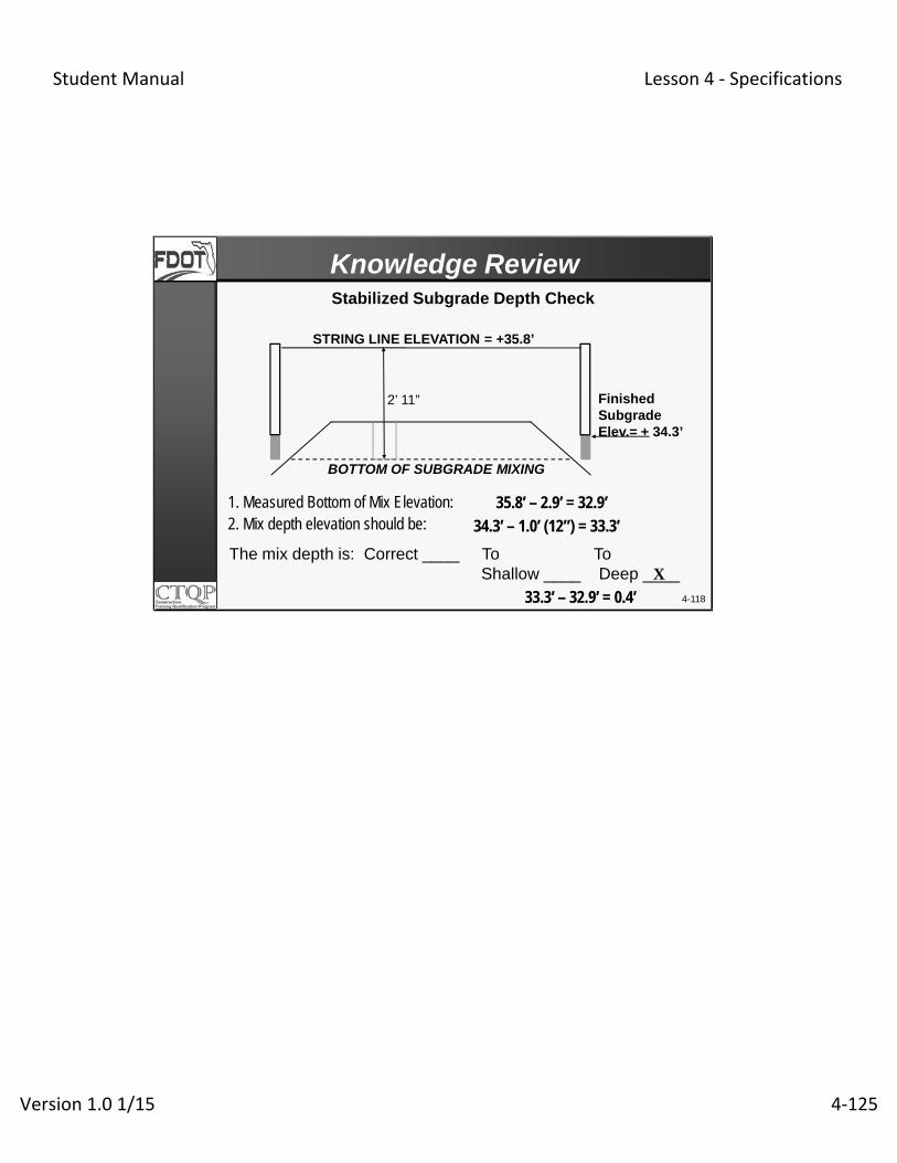
The mix depth is: Correct ____ To ToShallow ____ Deep ____
2. Mix depth elevation should be:1. Measured Bottom of Mix Elevation: 35.8’ – 2.9’ = 32.9’
34.3’ – 1.0’ (12”) = 33.3’
X
33.3’ – 32.9’ = 0.4’ 4-118
Stabilized Subgrade Depth Check
Knowledge Review
BOTTOM OF SUBGRADE MIXING
STRING LINE ELEVATION = +35.8’
FinishedSubgradeElev.= + 34.3’
2’ 11”

Student Manual Lesson 4 ‐ Specifications
Version 1.0 1/15 4‐126
4-119
Various Bases

Student Manual Lesson 4 ‐ Specifications
Version 1.0 1/15 4‐127
• Describe the various Base materials and theirplacement
• Describe the sampling and testing requirementsfor Base materials
• Describe the sampling and testing frequencies forBase materials
• Interpret significant inspector-related issues inStandard Specifications for Road and BridgeDesign (SSRBC)
4-120
Learning Outcomes

Student Manual Lesson 4 ‐ Specifications
Version 1.0 1/15 4‐128
4-121
Limerock Base

Student Manual Lesson 4 ‐ Specifications
Version 1.0 1/15 4‐129
LIMEROCK
GRADED AGGREGATE
SHELL BASE
RECLAIMED ASPHALT PAVEMENT (RAP)
4-122
Various Base Materials

Student Manual Lesson 4 ‐ Specifications
Version 1.0 1/15 4‐130
• One, if up to 6 inches total thickness, 8 inches with test strip.
• Multiple, of equal thickness, if more than 6 inches
• Minimum course thickness of 3”
200-5.2 NUMBER OF COURSES
4-123
Section 200- Rock Base

Student Manual Lesson 4 ‐ Specifications
Version 1.0 1/15 4‐131
200-5.2 Thick Lift Placement
• Engineer must approve before Contractor can begin using
• Not more than 8 inches compacted thickness
• Test section length of one LOT
• Five random QC tests on the bottom 6” in addition to the entire course thickness
• QC and one VT all passing
4-124
Section 200- Rock Base

Student Manual Lesson 4 ‐ Specifications
Version 1.0 1/15 4‐132
200-5.2 Thick Lift Placement
• Minimum % Max. Density – Average of 5 density tests performed on the thicker lift
• Identify test section w/ the compaction effort and material classification in the earthwork Density Report
• New test section if:• change in source of base material• rolling pattern/compaction effort changes
4-125
Section 200- Rock Base

Student Manual Lesson 4 ‐ Specifications
Version 1.0 1/15 4‐133
• LOT is a single lift of finished base not to exceed 500 ft.
• Before spreading next course, previous course must be tested and verified.
200-6.1 Compacting and Finishing Base
4-126
Section 200- Rock Base

Student Manual Lesson 4 ‐ Specifications
Version 1.0 1/15 4‐134
200-7.3.1.2 Depth & Surface Testing Requirements
• Contractor required to furnish labor & equipment to cut holes
• Correct if deficiency greater than ½” by scarifying andadding additional material
• Random number generator used to determine testlocations
4-127
Section 200- Rock Base

Student Manual Lesson 4 ‐ Specifications
Version 1.0 1/15 4‐135
200-7.3.1.2 Depth and Surface Testing Requirements
• Check with template & 15 feet straight edge parallel to the centerline
• Read to the nearest 0.1 inch (FM 5-534)
• Correct irregularities if greater than 1/4 inch
4-128
Section 200- Rock Base

Student Manual Lesson 4 ‐ Specifications
Version 1.0 1/15 4‐136
4-129
• 98% Modified Proctor
• 95% Modified Proctor for Shoulders
200-7.2.1 Acceptance Criteria (Density)
Section 200- Rock Base
200-7 Acceptance Program. 200-7.1 General Requirements: Meet the requirements of 120-10, except use 200-7.2 instead of 120-10.2, 200-7.3 instead of 120-10.3 and 200-7.4 instead of 120-10.4. 200-7.2 Acceptance Criteria: 200-7.2.1 Density: Within the entire limits of the width and depth of the base, obtain a minimum density in any LOT of 98% of modified Proctor maximum density as determined by FM 1-T 180, Method D or the pit proctor when using the pit proctor option. For shoulder only areas and bike/shared use paths, obtain a minimum density of 95% of the modified proctor maximum density as determined by FM 1-T 180, Method D or the pit proctor when using the pit proctor option.

Student Manual Lesson 4 ‐ Specifications
Version 1.0 1/15 4‐137
SMO tests RT sample for the corresponding VT
sample
4-130Test locations (Stations and offsets) are determinedusing a random number generator approved by the Engineer
QC is used
Did QC & VT compare w/in
4.5 pcf?
Contractor (QC) collects and splits sample for QC, VT & RT. (1 per 8 consecutive LOTs); QC tests sample
YES
NO
Does RT & QC compare w/in 4.5 pcf?
YES NOEng. collects & tests
remaining VT sample-VT results will be
used for all 16 LOTS
Eng. (VT) randomly selects one of the split samples (1 per 16 consecutive LOTs)
Maximum Density (Proctor)200-7.3, 7.4
Section 200- Rock Base
200-7.3 Additional Requirements: 200-7.3.1 Quality Control Testing: 200-7.3.1.1 Modified Proctor Maximum Density Requirement: Collect enough material to split and create three separate samples and retain two for the Engineer’s Verification and Resolution testing until the Engineer accepts the 16 LOTs represented by the samples. 200-7.3.2 Department Verification Tests: 200-7.3.2.1 Maximum Density: The Engineer will randomly select one of the remaining two split samples and test in accordance with FM 1-T 180, Method D. 200-7.4 Verification Comparison Criteria and Resolution Procedures: 200-7.4.1 Modified Proctor Maximum Density: The Engineer will compare the Verification test results of 200-7.3.2.1 to the corresponding Quality Control test results. If the test result is within 4.5 lb/ft3 of the QC test result, the LOTs will be verified. Otherwise, the Engineer will collect the Resolution split sample corresponding to the Verification sample tested. The State Materials Office or an AASHTO accredited laboratory designated by the State Materials Office will perform Resolution testing. The material will be sampled and tested in accordance with FM 1-T 180, Method D. The Engineer will compare the Resolution Test results with the Quality Control test results. If the Resolution Test result is within 4.5 lb/ft3 of the corresponding Quality Control test result, the Engineer will use the Quality Control test results for material acceptance purposes for each corresponding set
Student Manual Lesson 4 ‐ Specifications
Version 1.0 1/15 4‐138
of LOTs. If the Resolution test result is not within 4.5 lb/ft3 of the corresponding Quality Control test, the Engineer will collect the remaining Verification split sample for testing. Verification Test results will be used for material acceptance purposes for the LOTs in question.
Student Manual Lesson 4 ‐ Specifications
Version 1.0 1/15 4‐139
4-131Test locations (Stations and offsets) are determined using a random number generator approved by the Engineer
Perform new gauge comparison; Retest & re-verify the LOTs
Retest pass?
Eng. accepts 4 LOTs
Did VT meet min. req’ts?
Dept. (VT) tests 1 per 4 LOTs
YES
NO Contractor performs retest within 5’ of VT
Retest compare w/ VT?
YES
NO
YES
Contractor reworks & retest LOT; Eng. will re-verify.
Contractor (QC) tests 1 per LOT
As listed in Specifications
NO
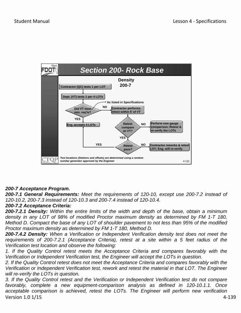
Density 200-7
Section 200- Rock Base
200-7 Acceptance Program. 200-7.1 General Requirements: Meet the requirements of 120-10, except use 200-7.2 instead of 120-10.2, 200-7.3 instead of 120-10.3 and 200-7.4 instead of 120-10.4. 200-7.2 Acceptance Criteria: 200-7.2.1 Density: Within the entire limits of the width and depth of the base, obtain a minimum density in any LOT of 98% of modified Proctor maximum density as determined by FM 1-T 180, Method D. Compact the base of any LOT of shoulder pavement to not less than 95% of the modified Proctor maximum density as determined by FM 1-T 180, Method D. 200-7.4.2 Density: When a Verification or Independent Verification density test does not meet the requirements of 200-7.2.1 (Acceptance Criteria), retest at a site within a 5 feet radius of the Verification test location and observe the following: 1. If the Quality Control retest meets the Acceptance Criteria and compares favorably with the Verification or Independent Verification test, the Engineer will accept the LOTs in question. 2. If the Quality Control retest does not meet the Acceptance Criteria and compares favorably with the Verification or Independent Verification test, rework and retest the material in that LOT. The Engineer will re-verify the LOTs in question. 3. If the Quality Control retest and the Verification or Independent Verification test do not compare favorably, complete a new equipment-comparison analysis as defined in 120-10.1.1. Once acceptable comparison is achieved, retest the LOTs. The Engineer will perform new verification

Student Manual Lesson 4 ‐ Specifications
Version 1.0 1/15 4‐140
testing. Acceptance testing will not begin on a new LOT until the Contractor has a gauge that meets the comparison requirements.

Student Manual Lesson 4 ‐ Specifications
Version 1.0 1/15 4‐141
4-132
Frequency of Testing
Section 200- Rock Base
200-7.2.2 Frequency: Conduct QC sampling and testing at a minimum frequency listed in the table below. The Engineer will perform Verification sampling and tests at a minimum frequency listed in the table below. 200-7.2.3 Pit Proctor: In lieu of Modified Proctor Maximum Density testing at the roadway, notify the Engineer in writing of a Contractor option to use the Pit Proctor supplied by the Department. The Modified Proctor maximum density frequency requirements of 200-7.2.2 shall not apply. The Department will determine the Pit Proctor from statistical analysis of the base rock Modified Proctor maximum density at Department approved mines. For posting of Mines and Pit Proctors for each calendar quarter refer to the State Materials Office internet website at http://www.dot.state.fl.us/statematerialsoffice/. Use the current posted Pit Proctor value in lieu of the Modified Proctor maximum density required by 200-7.2.1. Use the current posted Pit Proctor value for density acceptance during the quarter corresponding to the posting. Notify the Engineer in writing if returning to the provisions of 200-7.2 and 200-7.2.2 but do not re-elect to use the Pit Proctor until the start of the next calendar quarter.

Student Manual Lesson 4 ‐ Specifications
Version 1.0 1/15 4‐142

Student Manual Lesson 4 ‐ Specifications
Version 1.0 1/15 4‐143
4-133
Section 200- Rock Base
200-7.3.1.3 Surface & Thickness Reduced TestingFrequency:
• When no Resolution testing is required for 12consecutive verified LOTs
• Reduce frequency from ten per LOT to ten per twoLOTs
• Identifying the substantiating tests and notifying theEngineer in writing prior to starting reduced frequency oftesting.
200-7.3.1.3 Surface & Thickness Reduced Testing Frequency: When no Resolution testing is required for 12 consecutive verified LOTs, or if required, the QC test data was upheld, reduce the QC surface and/or thickness checks to one half the minimum requirements as stated in 200-7.2.2 (eg. Reduce frequency from ten per LOT to ten per two LOTs) by identifying the substantiating tests and notifying the Engineer in writing prior to starting reduced frequency of testing. If the Verification test fails, and Quality Control test data is not upheld by Resolution testing the Quality Control testing will revert to the original frequency of 200-7.2.2. The results of the Independent Verification testing will not affect the frequency of the Quality Control testing.

Student Manual Lesson 4 ‐ Specifications
Version 1.0 1/15 4‐144
• Apply prime coat:
• After passing density
• Moisture Content in top half of the base does not exceed optimum moisture
• Maintain crown & template while applying the surface course
200-8 Priming and Maintaining
4-134
Section 200- Rock Base

Student Manual Lesson 4 ‐ Specifications
Version 1.0 1/15 4‐145
• Carbonates > 70%
• At least 97% by weight shall pass a 3 ½ sieve
• Water sensitive clay mineral – Not greater than 3%
• LL not greater than 35% and non-plastic
• Average LBR > 100
4-135
Section 911- Limerock for Base & Stab. Base
Limerock Material for Base andStabilized Base- 911

Student Manual Lesson 4 ‐ Specifications
Version 1.0 1/15 4‐146
4-136
Delivery TicketRequired for Certified Base Materials

Student Manual Lesson 4 ‐ Specifications
Version 1.0 1/15 4‐147
204-2 Materials
• LBR not less than 100
• Material retained on No. 10 (2.00 mm):
• Soundness Loss- 15%
• % wear (L.A. Abrasion)
• Group 1- 45%
• Group 2- 65%
• LL < 25 and < 4 PI
• Group 2 sand equivalent value > 28
4-137
Section 204- Graded Aggregate Base

Student Manual Lesson 4 ‐ Specifications
Version 1.0 1/15 4‐148
• 100% Modified Proctor (roadway)
• 98% Modified Proctor (outside the traveled roadway)
• Surface Testing per 200-7
204- 6 & 7 Density and Surface Testing
4-138
Section 204- Graded Aggregate Base

Student Manual Lesson 4 ‐ Specifications
Version 1.0 1/15 4‐149
Materials: Shell
• Average LBR > 100 with individual > 90• Material passing No. 40 must be non-plastic• Carbonates 50% or greater• Gradation: See the specifications• Dredged and bank-run shells allowed• Watch for too much sand (will not bond)
4-139
Section 913- Shell Base

Student Manual Lesson 4 ‐ Specifications
Version 1.0 1/15 4‐150
4-140
Section 913A- Shell-Rock Base
Materials: Shell-Rock
• Average LBR > 100 with individual > 90• Material passing No. 40 must be non-plastic• Carbonates greater than 50% (average- less than
45% unacceptable• Gradation: See the specifications
913A-2 Deleterious Substances. Shell-rock materials shall not contain lumps of clay, organic matter, cherty or other extremely hard materials, or other substances not defined, in sufficient quantity as to be detrimental to the finishing, strength, or performance of the base. The material shall not contain loose, free silica sand in sufficient quantity to prevent bonding of the base, or to result in a surface which is susceptible to distortion under construction traffic, or accumulation of loose sand on the finished surface which precludes bonding of the bituminous tack coat with the base, nor shall the material contain more than 50% loose, free shells, corals or skeletal remain of other marine invertebrates (retained on the No. 4 sieve). Materials shall contain no water sensitive clay minerals. 913A-3 Physical and Chemical Properties. Shell-rock material shall meet the following physical and chemical properties: Limerock Bearing Ratio (LBR) (FM 5-515) - Production of this material shall be controlled so as to meet the following requirements for LBR value: The average of test values shall not be less than 100. No individual test value shall be less than 90. No two consecutive test values between 90 and 100.
Plasticity (AASHTO T 89 and AASHTO T 90) - That portion of the material passing the No. 40 sieve shall be non-plastic.
Carbonates (FM-5-514) - The minimum of the average percentage of carbonates of calcium and magnesium shall be 50. Material represented by any individual carbonate LOT average of less than 45% is unacceptable. Gradation Requirements - Materials classified as shell-rock shall be graded uniformly down to dust and in addition, meet the following specific requirements:

Student Manual Lesson 4 ‐ Specifications
Version 1.0 1/15 4‐151
Passing 3 1/2 inch sieve (maximum dimension not to exceed 6 inches)........................................minimum 97% Passing No. 4 sieve...........................maximum 70% Passing No. 200 sieve.......maximum 20% (washed)

Student Manual Lesson 4 ‐ Specifications
Version 1.0 1/15 4‐152
• Used only on paved shoulders, bike paths, other non-traffic applications
• Minimum asphalt content (4% or greater)
• No individual asphalt content less than 3.5%
• Number of courses:• One, if up to 6 inches compacted thickness• Multiple lifts if more than 6 inches
• ± 2% of optimum moisture when primed
• Use Speedy and convert it
• 95% of Modified Proctor
4-141
Section 283- RAP Base
Section 283- Reclaimed Asphalt Pavement Base
283-1 Description. Construct a base course composed of reclaimed asphalt pavement (RAP) material. Use RAP material as a base course only on non-limited access paved shoulders, shared use paths, or other non-traffic bearing applications. 283-2 Materials. Obtain the RAP material by either milling or crushing an existing asphalt pavement. Use material so that at least 97% (by weight) pass a 3-1/2 inch sieve and is graded uniformly down to dust. When the RAP material is from a Department project and the composition of existing pavement is known, the Engineer may approve material on the basis of the composition. When the composition of obtained RAP is not known, the following procedure will be used for approval: (1) Conduct a minimum of six extraction gradation analyses of the RAP material. Take samples at random locations in the stockpile. The average asphalt cement content of the six stockpile samples must be 4% or greater with no individual result below 3-1/2%. (2) Request the Engineer to make a visual inspection of the stockpile of RAP material. Based on this visual inspection of the stockpiled material and the results of the Contractor’s extraction gradation analyses, the Engineer will determine the suitability of the materials. (3) The Engineer may require crushing of stockpiled material to meet the gradation criterion. Perform all crushing before the material is placed. 283-3.2 Number of Courses: When the specified compacted thickness of the base is greater than 6 inches, construct the base in two courses. Place the first course to a thickness of approximately one half the total thickness of the finished base, or sufficient additional thickness to bear the weight of construction equipment without disturbing the subgrade. Except as might be permitted by the Engineer for special cases, conduct all

Student Manual Lesson 4 ‐ Specifications
Version 1.0 1/15 4‐153
RAP base construction operations for shoulders before placing the final pavement on the adjacent traveled roadway. 283-4.3 Density Requirements: Compact the material to a density of not less than 95% of maximum density as determined by FM 1-T 180. Where the width of the base construction is not sufficient to permit use of standard base compaction equipment, perform compaction using vibratory compactors, trench rollers, or other special equipment which will provide the density requirements specified herein. 283-4.4 Density Tests: Meet the requirements of 200-7 with the exception of 200-7.2.1. Within the entire limits of the width and depth of the base, obtain a minimum density in any LOT of 95% of the maximum density as determined by FM 1-T 180.

Student Manual Lesson 4 ‐ Specifications
Version 1.0 1/15 4‐154
Test Name Quality Control Verification
Modified Proctor
Max. Density (Proctor)One per eight consecutive LOTs
One per sixteen consecutive LOTs
Density One per LOT One per four LOTs
Roadway Surface Ten per LOT Witness
Roadway thickness Three per LOT Witness
4-142
200-7.2.2 Frequency
Testing Frequency- Various Bases
Mainline Pavement Lanes, Turn Lanes, Ramps, Parking Lots, ConcreteBox Culverts and Retaining Wall Systems

Student Manual Lesson 4 ‐ Specifications
Version 1.0 1/15 4‐155
4-143
Testing Frequency- Various Bases
Test Name Quality Control Verification
Modified Proctor
Max. Density (Proctor)One per two LOTs One per four LOTs
Density One per LOT One per two LOTs
Surface Five per 500 feet Witness
Roadway thicknessThree per 1000 consecutive feet
Witness
Shoulder Only, Bike/Shared Use Path and Sidewalk Construction
200-7.2.2 Frequency

Student Manual Lesson 4 ‐ Specifications
Version 1.0 1/15 4‐156
For Rock Base, the minimum course thickness is ____.
If thick lift compaction is approved for Rock Base, themaximum lift thickness (compacted) is ______.
4-144
Knowledge Review
3 inches
8 inches

Student Manual Lesson 4 ‐ Specifications
Version 1.0 1/15 4‐157
4-145
The density acceptance criteria for Rock Base is______.
The QC Thickness testing frequency for roadway rockbase is _______.
Knowledge Review
98% of FM 1 T-180
3 per LOT

Student Manual Lesson 4 ‐ Specifications
Version 1.0 1/15 4‐158
For shell and shell rock bases, the LBR value is to be______.
RAP material may only be used on ______.
4-146
Knowledge Review
100
Non-Traffic Applications

Student Manual Lesson 4 ‐ Specifications
Version 1.0 1/15 4‐159
4-147
The frequency for QC Maximum Density tests is________.
The frequency for Verification Roadway ThicknessWitness is _____.
Knowledge Review
1 per 8 LOTs
3 per 4 LOTs

Student Manual Lesson 4 ‐ Specifications
Version 1.0 1/15 4‐160
4-148
Section 548- Retaining Wall System

Student Manual Lesson 4 ‐ Specifications
Version 1.0 1/15 4‐161
4-149
Section 548- Retaining Wall System

Student Manual Lesson 4 ‐ Specifications
Version 1.0 1/15 4‐162
4-150
Learning Outcomes
• Understand Acceptable Backfill Materials
• Discuss Foundation Preparation
• Equipment restrictions for Backfill Placement
• Know the Acceptance Program
• Explain the Test Frequency

Student Manual Lesson 4 ‐ Specifications
Version 1.0 1/15 4‐163
Top of leveling pad,or bottom of wall toFinished Grade
Face of wall to lengthof reinforcement plus1 foot
Section 548- Retaining Wall System
MSE Wall Backfill Volume
4-151
548-2.6 Backfill Material: Meet the requirements of Sections 105, and 120 except as noted within this Section. …. …..The retaining wall volume is defined to extend from the top of the leveling pad or footing, or bottom of walls which do not have footing or leveling pads, to the finish grade line and from the face of the wall to a vertical plane passing through the end of the extreme wall component (straps, counterforts, etc.) plus 1 foot.

Student Manual Lesson 4 ‐ Specifications
Version 1.0 1/15 4‐164
548-2.6 Backfill Material:
• Provide certification to the Engineer that material meets requirements
Do not use backfill material with an avg. of more than 2.0% by weight of organic material or no individual test value of the three samples exceeds 3%.
Material to be non-plastic and liquid limit less than 15.
•Material with a pH between 5 and 9 is always acceptable.
•A pH lower than 5 may be used in some circumstances listedin 546-2.6.2
4-152
Section 548- Retaining Wall System
548-2.6.2 Compacted Select Backfill: Meet the requirements of Sections 105 and 120 except as noted within this Section. Have the backfill material tested for every soil type for pH, resistivity, sulfate and chloride content by a Department approved independent testing laboratory prior to placement. Provide certification to the Engineer that the results have met the requirements of this Section and are signed and sealed by a Professional Engineer, registered in the State of Florida. For constructing the retaining wall volume, do not use backfill material containing more than 2.0% by weight of organic material, as determined by FM 1-T 267 and by averaging the test results for three randomly selected samples from each stratum or stockpile of a particular material. If an individual test value of the three samples exceeds 3%, the stratum or stockpile will not be suitable for constructing the retaining wall volume. Ensure that the material is non-plastic as determined by AASHTO T90 and the liquid limit as determined by AASHTO T89 is less than 15. The pH, as determined by FM 5-550, shall not be lower than 5.0 and not higher than 9.0.Sources of select backfill material having a pH between 4.5 and 5.0, as determined by FM 5-550, may be used provided the interior face of the MSE wall panels have 3 inches of concrete cover over the reinforcement and the concrete used in the panels contains the following ingredients and proportions: 1. The quantity of cement replaced with Type F fly ash is 10% to 20% by weight. 2. The quantity of cement replaced with slag is 50% to 60% by weight. 3. Portland cement is 30% by weight of total cementitious material. 4. The total weight of the Type F fly ash and slag does not exceed 70% of total cementitious material.
Student Manual Lesson 4 ‐ Specifications
Version 1.0 1/15 4‐165
Do not place metallic pipe in backfill materials having a pH less than 5.0. Use backfill for walls using soil reinforcements that meets the following gradation limits determined in accordance with AASHTO T27 and FM 1-T 011:
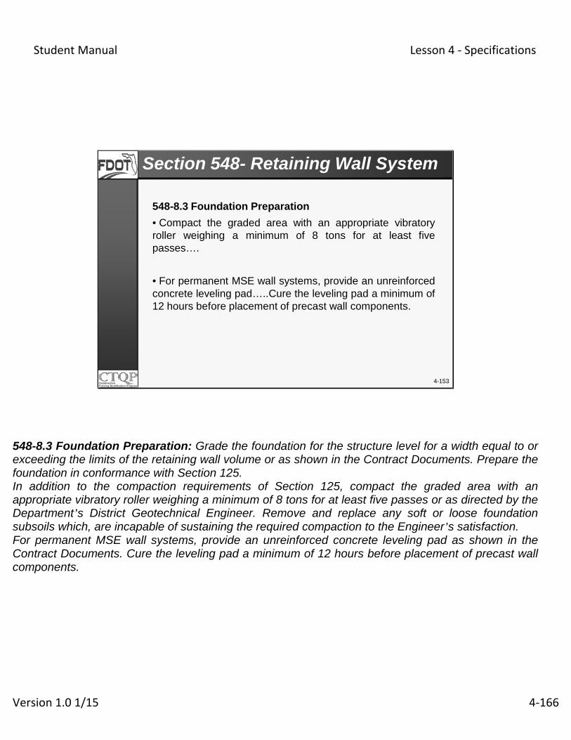
Student Manual Lesson 4 ‐ Specifications
Version 1.0 1/15 4‐166
548-8.3 Foundation Preparation
• Compact the graded area with an appropriate vibratoryroller weighing a minimum of 8 tons for at least fivepasses….
• For permanent MSE wall systems, provide an unreinforcedconcrete leveling pad…..Cure the leveling pad a minimum of12 hours before placement of precast wall components.
4-153
Section 548- Retaining Wall System
548-8.3 Foundation Preparation: Grade the foundation for the structure level for a width equal to or exceeding the limits of the retaining wall volume or as shown in the Contract Documents. Prepare the foundation in conformance with Section 125. In addition to the compaction requirements of Section 125, compact the graded area with an appropriate vibratory roller weighing a minimum of 8 tons for at least five passes or as directed by the Department’s District Geotechnical Engineer. Remove and replace any soft or loose foundation subsoils which, are incapable of sustaining the required compaction to the Engineer’s satisfaction. For permanent MSE wall systems, provide an unreinforced concrete leveling pad as shown in the Contract Documents. Cure the leveling pad a minimum of 12 hours before placement of precast wall components.

Student Manual Lesson 4 ‐ Specifications
Version 1.0 1/15 4‐167
548-8.5 Backfill Placement
• Do not allow equipment heavier than 8 tons closer than 3feet behind the wall face.
• Sheepfoot, grid rollers or other types of equipmentemploying a foot are not allowed.
• Ensure that the maximum lift thickness after compactiondoes not exceed 6 inches .
• Do not use saltwater.
4-154
Section 548- Retaining Wall System
548-8.5 Backfill Placement: ……Place the backfill closely following the erection of each course of precast components or soil reinforcement layers and spread by moving the machinery parallel to the wall face. Do not allow equipment heavier than 8 tons closer than 3 feet behind the wall face. Place backfill in a manner to avoid any damage or disturbance to the wall materials or misalignment of the facing materials. ……Sheepfoot, grid rollers or other types of equipment employing a foot are not allowed. Achieve compaction within 3 feet of the back of the wall face using a power operated roller or plate weighing less than 1,000 lbs. At a distance greater than 3 feet from the back of the wall, a vibratory roller may be used, provided that the frequency and amplitude combined with bulk weight of the roller has performed satisfactorily at a trial section of the same type of wall. A smooth wheel or rubber tire roller is considered adequate. Ensure that the maximum lift thickness after compaction does not exceed 6 inches. Decrease the lift thickness if necessary, to obtain specified density. ……Perform backfill compaction in a way that the compactor moves in a direction parallel to the wall face and proceeds from a distance not less than 3 feet behind the wall face toward the end of the soil reinforcement element. ……Ensure that the moisture content of the backfill material prior to and during compaction is uniformly distributed throughout each layer of material. Use backfill material having a placement moisture content at the dry side of the Optimum Moisture content. To achieve the required

Student Manual Lesson 4 ‐ Specifications
Version 1.0 1/15 4‐168
compaction moisture content, use water that meets the requirements of Section 923. Do not use saltwater. Do not transport excessively moist backfill materials to the site for any reason. The Engineer will determine the Optimum Moisture Content in accordance with FM 5-521…..
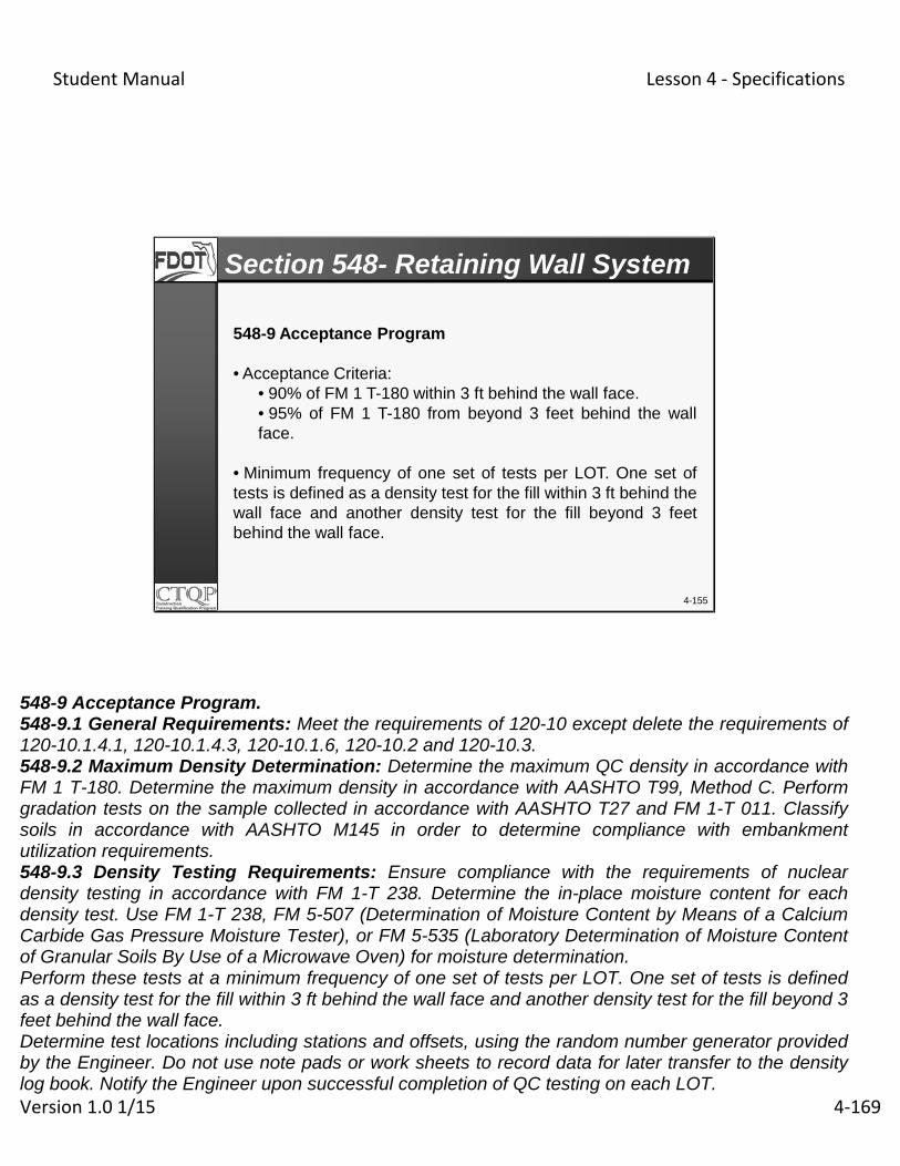
Student Manual Lesson 4 ‐ Specifications
Version 1.0 1/15 4‐169
548-9 Acceptance Program
• Acceptance Criteria:• 90% of FM 1 T-180 within 3 ft behind the wall face.• 95% of FM 1 T-180 from beyond 3 feet behind the wallface.
• Minimum frequency of one set of tests per LOT. One set oftests is defined as a density test for the fill within 3 ft behind thewall face and another density test for the fill beyond 3 feetbehind the wall face.
4-155
Section 548- Retaining Wall System
548-9 Acceptance Program. 548-9.1 General Requirements: Meet the requirements of 120-10 except delete the requirements of 120-10.1.4.1, 120-10.1.4.3, 120-10.1.6, 120-10.2 and 120-10.3. 548-9.2 Maximum Density Determination: Determine the maximum QC density in accordance with FM 1 T-180. Determine the maximum density in accordance with AASHTO T99, Method C. Perform gradation tests on the sample collected in accordance with AASHTO T27 and FM 1-T 011. Classify soils in accordance with AASHTO M145 in order to determine compliance with embankment utilization requirements. 548-9.3 Density Testing Requirements: Ensure compliance with the requirements of nuclear density testing in accordance with FM 1-T 238. Determine the in-place moisture content for each density test. Use FM 1-T 238, FM 5-507 (Determination of Moisture Content by Means of a Calcium Carbide Gas Pressure Moisture Tester), or FM 5-535 (Laboratory Determination of Moisture Content of Granular Soils By Use of a Microwave Oven) for moisture determination. Perform these tests at a minimum frequency of one set of tests per LOT. One set of tests is defined as a density test for the fill within 3 ft behind the wall face and another density test for the fill beyond 3 feet behind the wall face. Determine test locations including stations and offsets, using the random number generator provided by the Engineer. Do not use note pads or work sheets to record data for later transfer to the density log book. Notify the Engineer upon successful completion of QC testing on each LOT.

Student Manual Lesson 4 ‐ Specifications
Version 1.0 1/15 4‐170
548-7.4 Acceptance Criteria: Obtain a minimum density of 90% of the maximum dry density as determined by FM 1 T-180 within 3 ft behind the wall face and obtain a minimum density of 95% of the maximum dry density as determined by FM 1 T-180 from beyond 3 feet behind the wall face.

Student Manual Lesson 4 ‐ Specifications
Version 1.0 1/15 4‐171
548-7.5 Frequency
4-156
Section 548- Retaining Wall System
Test Name Quality Control Verification
Maximum Density
One per soil type One per soil type
DensityOne set of tests per LOT One set of tests per four LOTS for each
type of QC test.
GradationOne per Maximum Density
One per Maximum Density
LL&PIOne per Maximum Density
One per Maximum Density
Soil Classification
One per Maximum Density
One per Maximum Density
Organic Content
One per soil type One per soil type

Student Manual Lesson 4 ‐ Specifications
Version 1.0 1/15 4‐172
Traffic Separator
4-157
Design Standards

Student Manual Lesson 4 ‐ Specifications
Version 1.0 1/15 4‐173
FlexiblePavement Stabilized Subgrade
4-158
302- Traffic Separators

Student Manual Lesson 4 ‐ Specifications
Version 1.0 1/15 4‐174
4-159
LIMS

Student Manual Lesson 4 ‐ Specifications
Version 1.0 1/15 4‐175
SAMPLE LOG-IN: Sample is LOGGED IN. Data entry by Samplers (or their Data-entry person)
SAMPLE RECEIPT: Sample is RECEIVED by the lab assigned in the login stage.
Lab Tests: Data Entry by Lab
TEST RESULT ENTRY: Individual test results entered & the test PASSES (or FAILS) based on Specification requirements.
Result Entry & Decision by Testers (or their Data-entry person)
4-160
LIMS Life Cycle
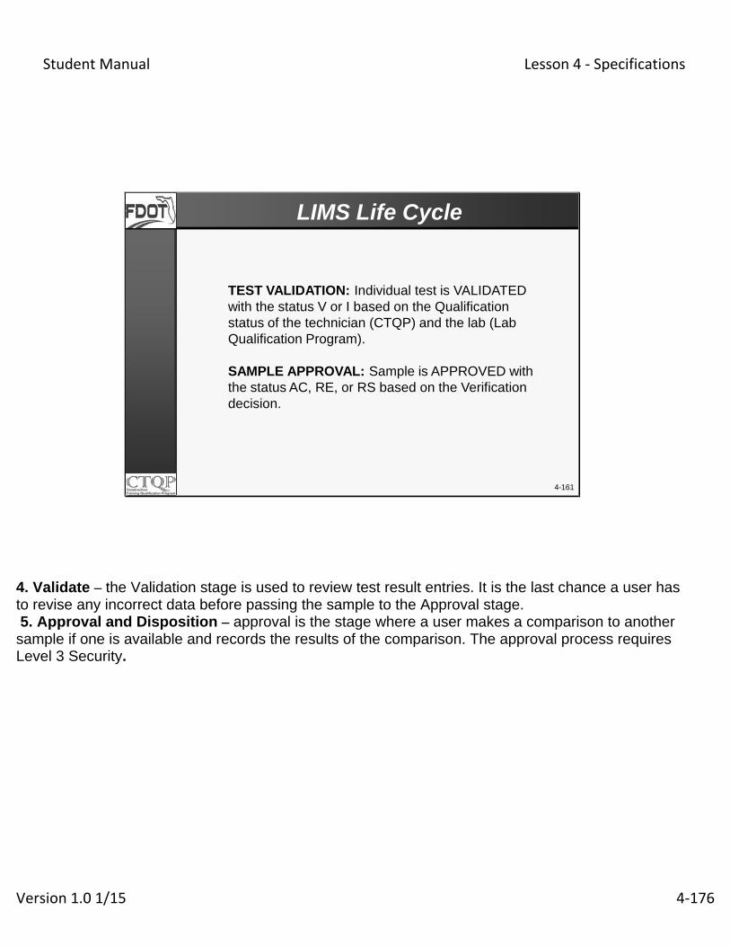
Student Manual Lesson 4 ‐ Specifications
Version 1.0 1/15 4‐176
4-161
TEST VALIDATION: Individual test is VALIDATED with the status V or I based on the Qualification status of the technician (CTQP) and the lab (Lab Qualification Program).
SAMPLE APPROVAL: Sample is APPROVED with the status AC, RE, or RS based on the Verification decision.
LIMS Life Cycle
4. Validate – the Validation stage is used to review test result entries. It is the last chance a user has to revise any incorrect data before passing the sample to the Approval stage. 5. Approval and Disposition – approval is the stage where a user makes a comparison to another sample if one is available and records the results of the comparison. The approval process requires Level 3 Security.

Student Manual Lesson 4 ‐ Specifications
Version 1.0 1/15 4‐177
4-162
POST-APPROVAL DISPOSITION: Some samples are assigned a “DISPOSITION” codes based on the pay decision and final disposition.
For Contractor Quality Control (CQC) Testing: The V Lab/ V field office assigns codes to the QC Samples.
No codes are assigned to Verification (V), Resolution (R) samples or Independent Verification (IV).
LIMS Life Cycle
Disposition is part of the Approval life cycle stage. All samples must be approved. Not all samples get a disposition code. NOTE: Login, Receipt, Result Entry and Validation can be performed by a user with LIMS Security Level 2. Approval and Disposition must be performed by a user with Level 3 Security Disposition Codes Disposition codes are assigned to: Q level samples on CQC samples V level samples on non-CQC samples No disposition codes are assigned to IA, IV level samples. No disposition codes are assigned to resolution samples. The disposition codes are: AT Action Taken (for Manufactured Products) FD Full Pay per Engineer’s Decision FS Full Pay per Specifications (see note) FX No Further Action Required NA Research Sample or In-house Information Only ND No Pay per Engineer’s Decision RD Reduced Pay per Engineer’s Decision RR Remove and Replace

Student Manual Lesson 4 ‐ Specifications
Version 1.0 1/15 4‐178
RS Reduced Pay per Specifications

Student Manual Lesson 4 ‐ Specifications
Version 1.0 1/15 4‐179
• Sample Data Entry
• Result Data Entry for Field Tests
• Sample Approval
• Post-Approval Disposition forNon-CQC Samples
• Final Project Certification Process
• Process Contractor & CCEI Access Requests
Resident Office and Consultant CEI
4-163
LIMS Responsibilities

Student Manual Lesson 4 ‐ Specifications
Version 1.0 1/15 4‐180
• Submit Request Forms for all Subs & Producers(Prime Contractors Only)
• QC Sample Data Entry
• QC Sample Post Approval Disposition
• Request “Authorized Lab ID” for Field Office
Contractors, Producers and Labs
4-164
LIMS Responsibilities

Student Manual Lesson 4 ‐ Specifications
Version 1.0 1/15 4‐181
4-165
LIMS

Student Manual Lesson 4 ‐ Specifications
Version 1.0 1/15 4‐182
4-166

Student Manual Lesson 4 ‐ Specifications
Version 1.0 1/15 4‐183
4-167
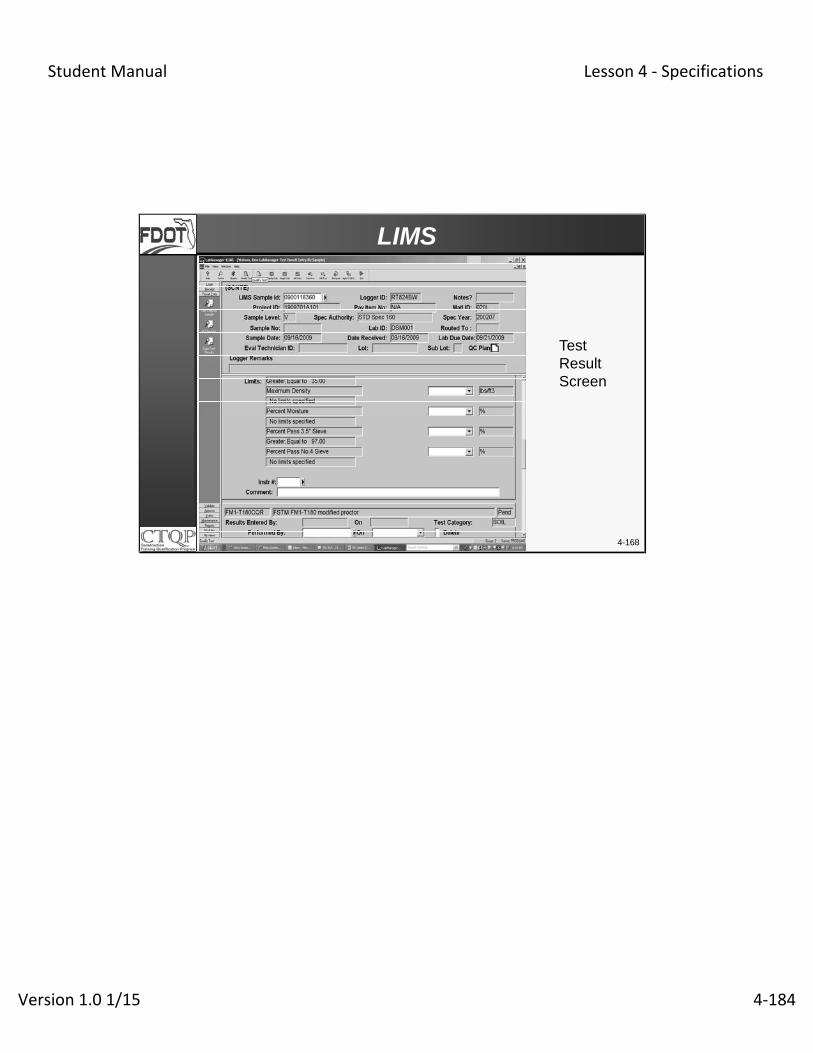
Student Manual Lesson 4 ‐ Specifications
Version 1.0 1/15 4‐184
4-168
LIMS
TestResultScreen

Student Manual Lesson 4 ‐ Specifications
Version 1.0 1/15 4‐185
4-169
LIMS
Validation Screen
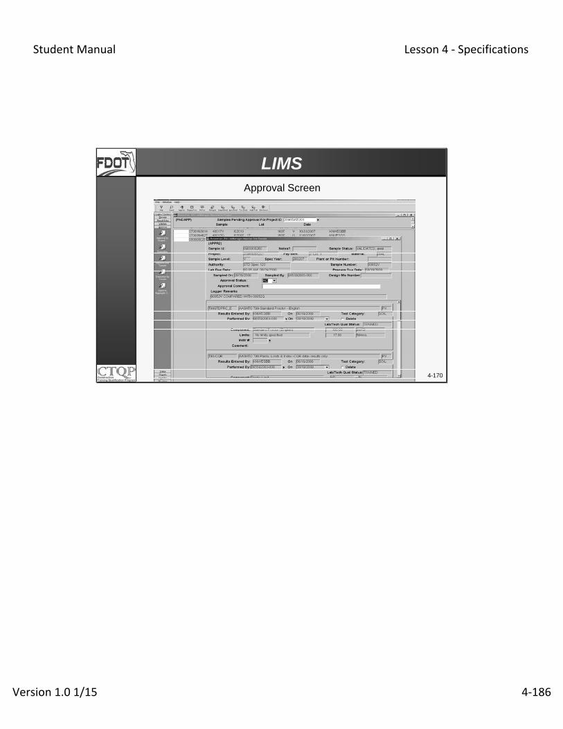
Student Manual Lesson 4 ‐ Specifications
Version 1.0 1/15 4‐186
4-170
LIMSApproval Screen

Student Manual Lesson 4 ‐ Specifications
Version 1.0 1/15 4‐187