lesson 7 - university of nairobi · pdf filelesson 7 • electromagnetic induction ......
TRANSCRIPT

Lesson 7
• Electromagnetic Induction
• Faraday’s Law
• Lenz’s Law
• Self-Inductance
• RL Circuits
• Energy in a Magnetic Field
• Mutual Inductance
• Oscillations in an LC Circuit
• The RLC Circuit
• Alternating Current
• Electromagnetic waves
Electromagnetic Induction
• The principle of induction
• Any electric field that changes over time will produce a magnetic field in the space around it.
• Any magnetic field that changes over time will produce an electric field in the space around it.

Faraday’s Law of Induction Faraday found that an electric current can be induced in a circuit (the secondary circuit in our setup) by a changing magnetic field. The induced current exists for only a short time while the magnetic field through the secondary coil is changing. Once the magnetic field reaches a steady value, the current in the secondary coil disappears. In effect, the secondary circuit behaves as though a source of emf were connected to it for a short time. It is customary to say that an induced emf is produced in the secondary circuit by the changing magnetic field.
the SI unit for magnetic flux is the tesla – square meter, which is called the weber (abbreviated Wb).

Faraday’s Law of Induction
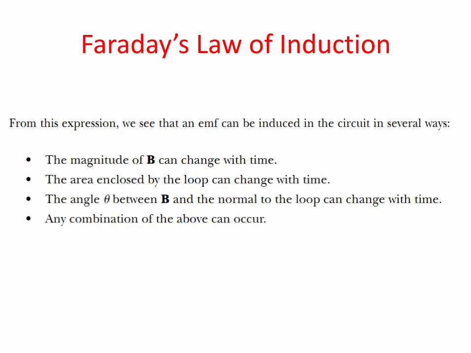
Faraday’s Law of Induction

Faraday’s Law of Induction
Example : One Way to Induce an emf in a Coil
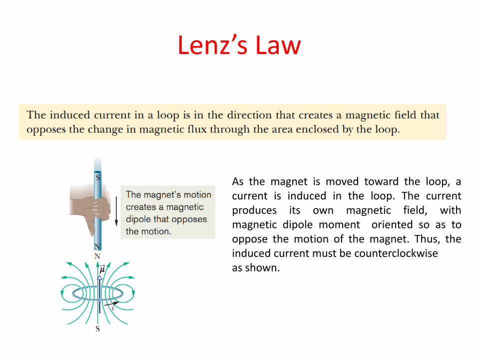
Lenz’s Law
As the magnet is moved toward the loop, a current is induced in the loop. The current produces its own magnetic field, with magnetic dipole moment oriented so as to oppose the motion of the magnet. Thus, the induced current must be counterclockwise as shown.

Self-Inductance Consider the circuit shown in the figure. After the switch is closed, the current produces a magnetic flux through the area enclosed by the loop. As the current increases toward its equilibrium value, this magnetic flux changes in time and induces an emf in the loop.
This effect is called self-induction because the changing flux through the circuit and the resultant induced emf arise from the circuit itself. The emf εL set up in this case is called a self-induced emf.
(a) A current in the coil produces a magnetic field directed to the left. (b) If the current increases, the increasing magnetic flux creates an induced emf in the coil having the polarity shown by the dashed battery. (c) The polarity of the induced emf reverses if the current decreases.

Self-Inductance
• To obtain a quantitative description of self-induction, we recall from Faraday’s law that the induced emf is equal to the negative of the time rate of change of the magnetic flux.
• The magnetic flux is proportional to the magnetic field due to the current, which in turn is proportional to the current in the circuit.
• Therefore, a self-induced emf is always proportional to the time rate of change of the current. For any coil, we find that

Self-Inductance • Example: Inductance of a Solenoid
Self-Inductance
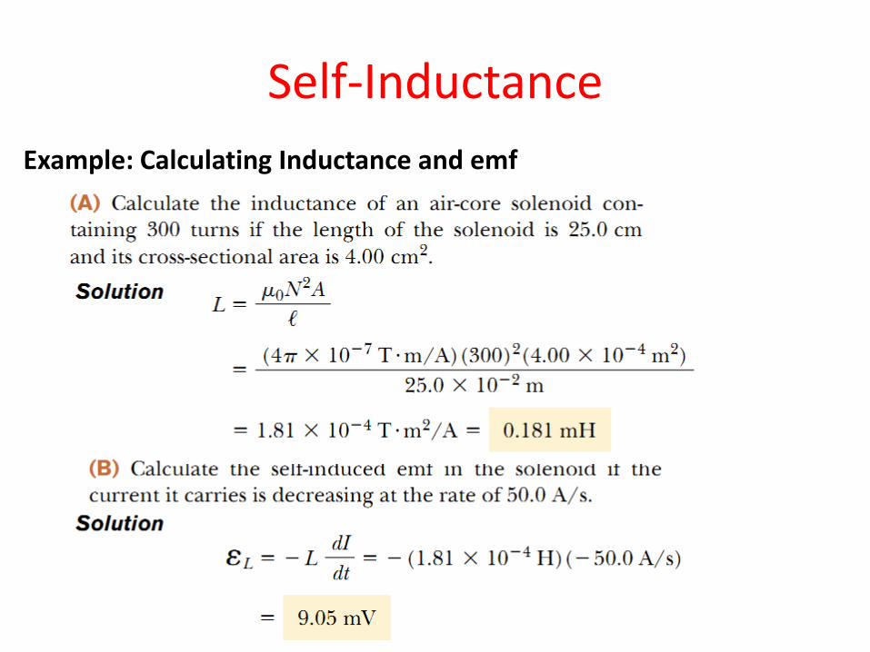
Example: Calculating Inductance and emf

RL Circuits • A circuit element that has a large self-inductance is called an
inductor and has the circuit symbol
• Because the inductance of the inductor results in a back emf, an inductor in a circuit opposes changes in the current in that circuit. The inductor attempts to keep the current the same as it was before the change occurred.
• If the battery voltage in a circuit is increased so that the current rises, the inductor opposes this change, and the rise is not instantaneous.
• If the battery voltage is decreased, the presence of the inductor results in a slow drop in the current rather than an immediate drop.
• Thus, the inductor causes the circuit to be “sluggish” as it reacts to changes in the voltage.

RL Circuits
A series RL circuit. As the current increases toward its maximum value, an emf that opposes the increasing current is induced in the inductor.
Using Kirchhoff's Law

RL Circuits
A mathematical solution of the equation represents the current in the circuit as a function of time. To find this solution, we change variables for convenience, letting

RL Circuits
Plot of the current versus time for the RL circuit Plot of dI/dt versus time for the RL circuit

RL Circuits
• Example: Time Constant of an RL Circuit (i) Find the time constant of the circuit shown in the Figure
Solution
(ii) The switch is closed at t = 0. Calculate the current in the circuit at t = 2.00ms.
Solution

Energy in a Magnetic Field
Although this expression was derived for the special case of a solenoid, it is valid for any region of space in which a magnetic field exists.

Energy in a Magnetic Field
• Different energy-storage mechanisms are at work in capacitors, inductors, and resistors. A capacitor stores a given amount of energy for a fixed charge on its plates; as more charge is delivered, more energy is delivered.
• An inductor stores a given amount of energy for constant current; as the current increases, more energy is delivered.
• Energy delivered to a resistor is transformed to internal energy

Mutual Inductance
• Very often, the magnetic flux through the area enclosed by a circuit varies with time because of time-varying currents in nearby circuits. This condition induces an emf through a process known as mutual induction, so called because it depends on the interaction of two circuits
A cross-sectional view of two adjacent coils. A current in coil 1 sets up a magnetic field and some of the magnetic field lines pass through coil 2.

Mutual Inductance
• The mutual inductance M12 of coil 2 with respect to coil 1:
If the current I1 varies with time, we see from Faraday’s law that the emf induced by coil 1 in coil 2 is
In mutual induction, the emf induced in one coil is always proportional to the rate at which the current in the other coil is changing.

Oscillations in an LC Circuit
Example: Oscillations in an LC Circuit
In the Figure, the capacitor is initially charged when switch S1 is open and S2 is closed. Switch S2 is then opened, removing the battery from the circuit, and the capacitor remains charged. Switch S1 is then closed, so that the capacitor is connected directly across the inductor.
(i) Find the frequency of oscillation of the circuit.

Oscillations in an LC Circuit
(ii) What are the maximum values of charge on the capacitor and current in the circuit?

Oscillations in an LC Circuit
(iii) Determine the charge and current as functions of time.

The RLC Circuit
A series RLC circuit.
Switch S1 is closed and the capacitor is charged. S1 is then opened and, at t = 0, switch S2 is closed.
Because the rate of energy transformation to internal energy within a resistor is I2R , we have
Using Kirchhoff's Law

Alternating Current
AC Sources

Alternating Current
At any instant, the algebraic sum of the voltages around a closed loop in a circuit must be zero (Kirchhoff’s loop rule)
Resistors in an AC Circuit

Alternating Current
Plots of the instantaneous current iR and instantaneous voltage ΔvR across a resistor as functions of time. The current is in phase with the voltage, which means that the current is zero when the voltage is zero, maximum when the voltage is maximum, and minimum when the voltage is minimum. At time τ=T, one cycle of the time-varying voltage and current has been completed.
The root-mean-square, rms current. The average power delivered to a resistor that carries an alternating current is
Resistors in an AC Circuit

Alternating Current
• Example: What Is the rms Current?

Alternating Current
Inductors in an AC Circuit

Alternating Current
Example : A Purely Inductive AC Circuit In a purely inductive AC circuit, L = 25.0 mH and the rms voltage is 150 V. Calculate the inductive reactance and rms current in the circuit if the frequency is 60.0 Hz.
Solution
Alternating Current
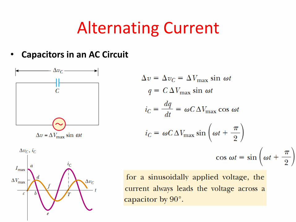
• Capacitors in an AC Circuit

Alternating Current

Alternating Current
• The RLC Series Circuit
(a) A series circuit consisting of a resistor, an inductor, and a capacitor connected to an AC source. (b) Phase relationships for instantaneous voltages in the series RLC circuit.
The current at all points in a series AC circuit has the same amplitude and phase.

Alternating Current
The denominator of the fraction plays the role of resistance and is called the impedance Z of the circuit:

Alternating Current

Electromagnetic Waves • The Spectrum of Electromagnetic Waves
Electromagnetic waves, which are predicted by Maxwell’s equations, have the following properties:
1. The electric field and the magnetic field each satisfy a wave equation.
2. The waves travel through a vacuum with the speed of light c, where
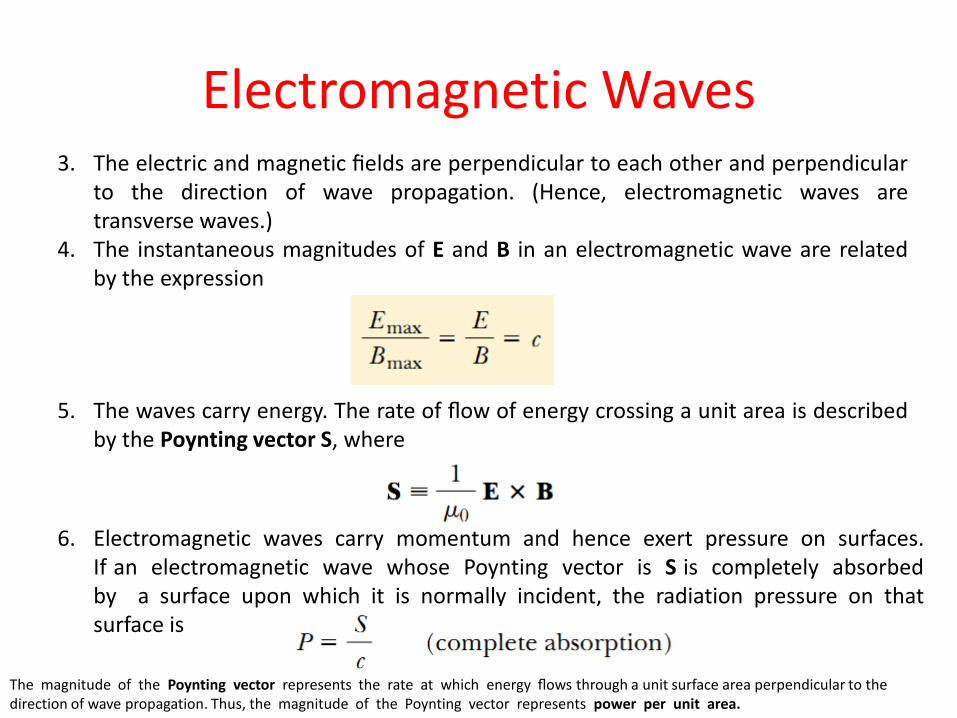
Electromagnetic Waves 3. The electric and magnetic fields are perpendicular to each other and perpendicular
to the direction of wave propagation. (Hence, electromagnetic waves are transverse waves.)
4. The instantaneous magnitudes of E and B in an electromagnetic wave are related by the expression
5. The waves carry energy. The rate of flow of energy crossing a unit area is described by the Poynting vector S, where
6. Electromagnetic waves carry momentum and hence exert pressure on surfaces. If an electromagnetic wave whose Poynting vector is S is completely absorbed by a surface upon which it is normally incident, the radiation pressure on that surface is
The magnitude of the Poynting vector represents the rate at which energy flows through a unit surface area perpendicular to the direction of wave propagation. Thus, the magnitude of the Poynting vector represents power per unit area.

Electromagnetic Waves
• The electric and magnetic fields of a sinusoidal plane electromagnetic wave propagating in the positive x direction can be written
Representation of a sinusoidal, linearly polarized plane electromagnetic wave moving in the positive x direction with velocity c. The wave at some instant. Note the sinusoidal variations of E and B with x.
The average value of the Poynting vector for a plane electromagnetic wave has a magnitude
Electromagnetic Waves
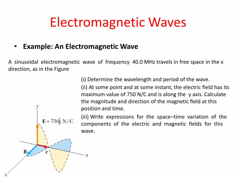
• Example: An Electromagnetic Wave
A sinusoidal electromagnetic wave of frequency 40.0 MHz travels in free space in the x direction, as in the Figure
(i) Determine the wavelength and period of the wave.
(ii) At some point and at some instant, the electric field has its maximum value of 750 N/C and is along the y axis. Calculate the magnitude and direction of the magnetic field at this position and time.
(iii) Write expressions for the space–time variation of the components of the electric and magnetic fields for this wave.

Electromagnetic Waves • Solution
(iii)
(ii)
(i)