letter of transmittal - york university · • video core iv 3d graphics core it has an armv7...
TRANSCRIPT

Letter of Transmittal
EECS 3215 Project report: An interlinking embedded system with social media. This report was written on Monday,
April 18, 2016.
This report shows how the interlinking embedded system with social media was achieved. Also, this report
demonstrates the organization of the hardware/software of this embedded system, as well as how it works.
If you have any further questions, please do not hesitate to contact me at this email address:
Sincerely,
Tai Dinh

Department of Electrical Engineering and Computer Science
EECS 3215
EMBEDDED SYSTEMS
2015-2016 Winter Term
Project Report
Amanpreet Singh Walia 212938734
Juan Gabriel Loja 212786406
Tai Dinh 212501821
Due Date: Tuesday, April 20, 2016
The work in this report is our own. We have read and understood York University’s academic dishonesty policy and we did not violate the senate dishonesty policy in writing this report. Signature __________________
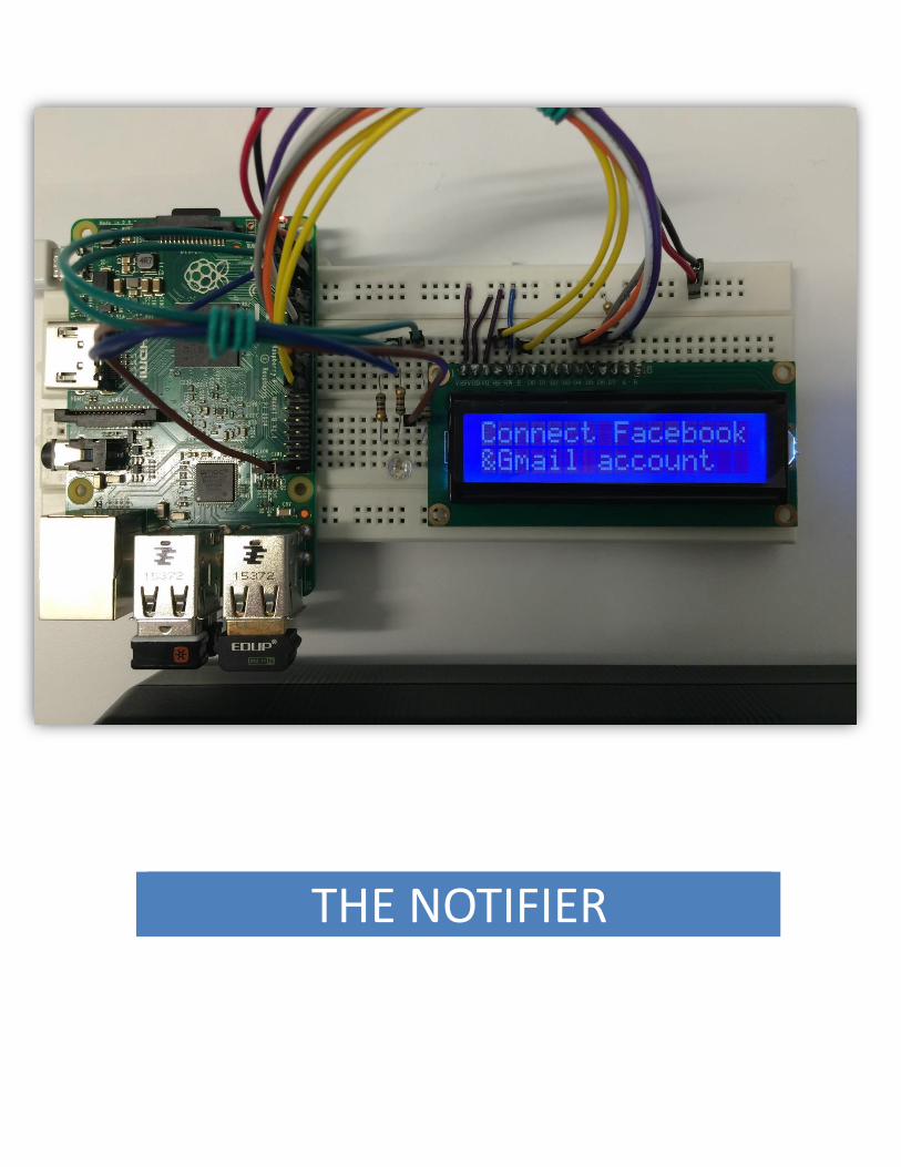
THE NOTIFIER

Executive Summary
This project report contains detailed description of our project with all the hardware and software
components involved. This involves setup procedure, connections, software intricacies and the respective code
involved. Our project is related to connecting Embedded systems with social media web to utilize the benefits
of internet connected world as much as possible. For this particular project, we use Facebook and Gmail as
the social media platform for showing the proof of concept. However, it can be extended suitably to nearly
all other existing platforms. On Embedded systems side we chose Raspberry pi 2 running Raspbian OS as the
device of our choice. For user interface we use 16X2 LCD and Wi-Fi module to achieve the task. All necessary
information related to project is available in detailed format across the report.

Acknowledgements
Working on this project was a source of immense knowledge to us. We would like to express our sincere,
grateful gratitude to our instructor and teaching assistants for their guidance and valuable support in this
project. This project cannot be completed without the effort and co-operation from our group members. We
would also like to thank our parents for their love and support.
Amanpreet Walia
Juan Gabriel Loja
Tai Dinh
Introduction
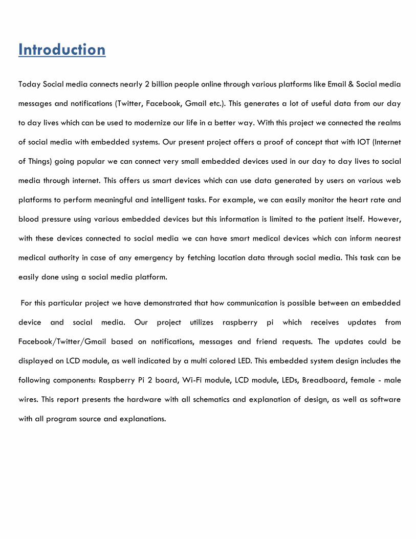
Today Social media connects nearly 2 billion people online through various platforms like Email & Social media
messages and notifications (Twitter, Facebook, Gmail etc.). This generates a lot of useful data from our day
to day lives which can be used to modernize our life in a better way. With this project we connected the realms
of social media with embedded systems. Our present project offers a proof of concept that with IOT (Internet
of Things) going popular we can connect very small embedded devices used in our day to day lives to social
media through internet. This offers us smart devices which can use data generated by users on various web
platforms to perform meaningful and intelligent tasks. For example, we can easily monitor the heart rate and
blood pressure using various embedded devices but this information is limited to the patient itself. However,
with these devices connected to social media we can have smart medical devices which can inform nearest
medical authority in case of any emergency by fetching location data through social media. This task can be
easily done using a social media platform.
For this particular project we have demonstrated that how communication is possible between an embedded
device and social media. Our project utilizes raspberry pi which receives updates from
Facebook/Twitter/Gmail based on notifications, messages and friend requests. The updates could be
displayed on LCD module, as well indicated by a multi colored LED. This embedded system design includes the
following components: Raspberry Pi 2 board, Wi-Fi module, LCD module, LEDs, Breadboard, female - male
wires. This report presents the hardware with all schematics and explanation of design, as well as software
with all program source and explanations.

Hardware Components and Schematics
Raspberry Pi
Raspberry Pi 2 Pin Diagram
The Raspberry Pi 2 Model B is the second generation Raspberry Pi. It contains:
• A 900MHz quad-core ARM Cortex-A7 CPU
• 1GB RAM
• 4 USB ports
• 40 GPIO pins
• Full HDMI port
• Ethernet port
• Combined 3.5mm audio jack and composite video
• Camera interface (CSI)
• Display interface (DSI)
• Micro SD card slot
• Video Core IV 3D graphics core
It has an ARMv7 processor which can run the full range of ARM GNU/Linux distributions, including Snappy
Ubuntu Core, as well as Microsoft Windows 10.
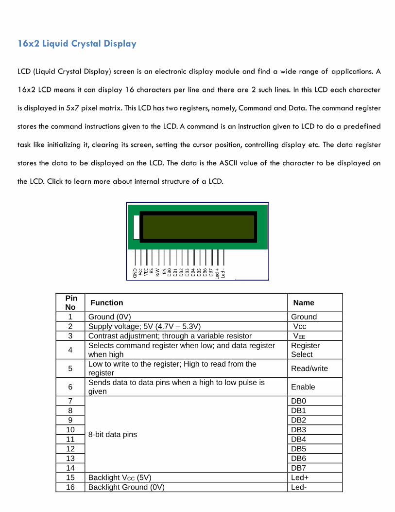
16x2 Liquid Crystal Display
LCD (Liquid Crystal Display) screen is an electronic display module and find a wide range of applications. A
16x2 LCD means it can display 16 characters per line and there are 2 such lines. In this LCD each character
is displayed in 5x7 pixel matrix. This LCD has two registers, namely, Command and Data. The command register
stores the command instructions given to the LCD. A command is an instruction given to LCD to do a predefined
task like initializing it, clearing its screen, setting the cursor position, controlling display etc. The data register
stores the data to be displayed on the LCD. The data is the ASCII value of the character to be displayed on
the LCD. Click to learn more about internal structure of a LCD.
Pin No
Function Name
1 Ground (0V) Ground
2 Supply voltage; 5V (4.7V – 5.3V) Vcc
3 Contrast adjustment; through a variable resistor VEE
4 Selects command register when low; and data register when high
Register Select
5 Low to write to the register; High to read from the register
Read/write
6 Sends data to data pins when a high to low pulse is given
Enable
7
8-bit data pins
DB0
8 DB1
9 DB2
10 DB3
11 DB4
12 DB5
13 DB6
14 DB7
15 Backlight VCC (5V) Led+
16 Backlight Ground (0V) Led-

RGB LED
Diffused 5mm tri-color LED with separate red, green and blue LED chips inside! Nice indicator, and fun to
color-swirl. 60 degree viewing angle. We like diffused RGB LEDs because they color mix inside instead of
appearing as 3 distinct LEDs.
These are Common-Anode type which means you connect one pin to 5V or so and then tie the other three
legs to ground through a resistor. We carry and use CA more than CC because multi-LED driver chips (such
as the TLC5940/TLC5941) are often designed exclusively for CA and can't be used with Common-Cathode.
5mm diameter
Red: 630 nm wavelength, Green: 525 nm, Blue: 430 nm
Red: 2.1-2.5V Forward Voltage, at 20mA current, Green: 3.8-4.5V, Blue: 3.8-4.5V
Red: 500 mcd typical brightness, Green: 600 mcd, Blue: 300 mcd
Raspberry Pi USB Wi-Fi Dongle
This device is used to connect to Wi-Fi network through USB protocol and onboard drivers. The USB Network
Card has a launching function which can launch Wi-Fi signal to your phone under the premise of your computer
getting online.
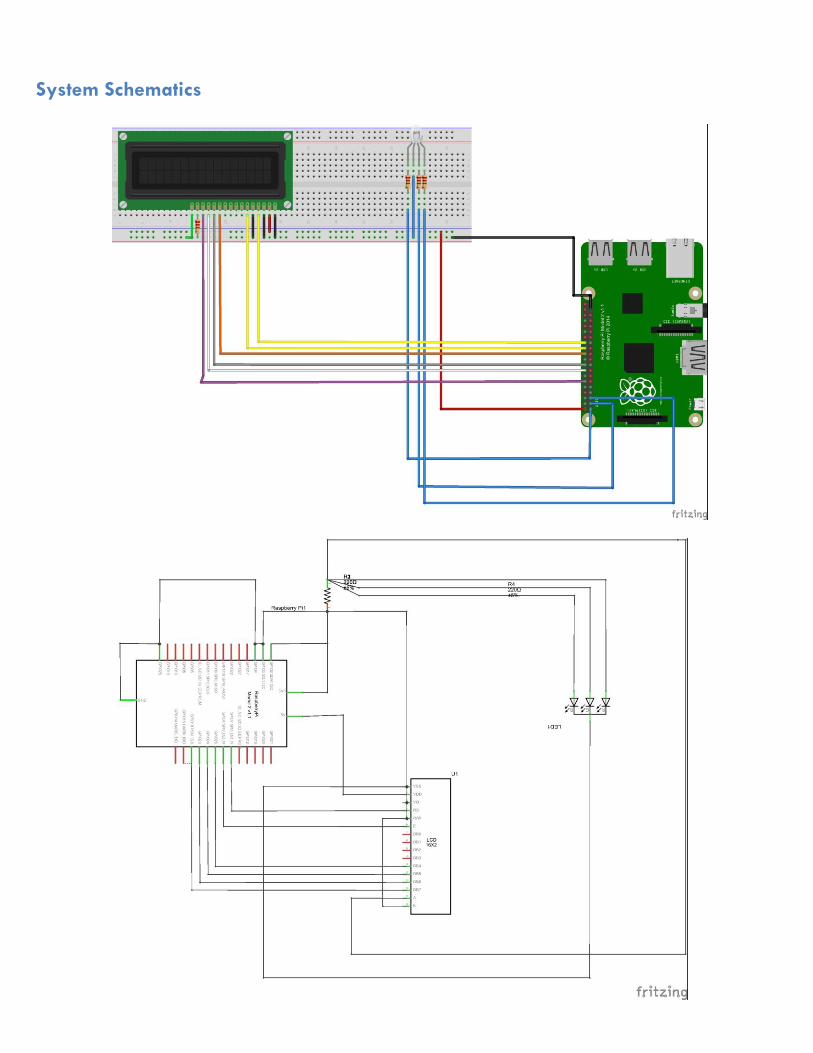
System Schematics
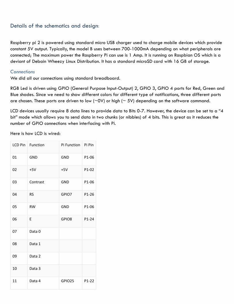
Details of the schematics and design:
Raspberry pi 2 is powered using standard micro USB charger used to charge mobile devices which provide
constant 5V output. Typically, the model B uses between 700-1000mA depending on what peripherals are
connected; The maximum power the Raspberry Pi can use is 1 Amp. It is running on Raspbian OS which is a
deviant of Debain Wheezy Linux Distribution. It has a standard microSD card with 16 GB of storage.
Connections
We did all our connections using standard breadboard.
RGB Led is driven using GPIO (General Purpose Input-Output) 2, GPIO 3, GPIO 4 ports for Red, Green and
Blue shades. Since we need to show different colors for different type of notifications, three different ports
are chosen. These ports are driven to low (~0V) or high (~ 5V) depending on the software command.
LCD devices usually require 8 data lines to provide data to Bits 0-7. However, the device can be set to a “4
bit” mode which allows you to send data in two chunks (or nibbles) of 4 bits. This is great as it reduces the
number of GPIO connections when interfacing with Pi.
Here is how LCD is wired:
LCD Pin Function Pi Function Pi Pin
01 GND GND P1-06
02 +5V +5V P1-02
03 Contrast GND P1-06
04 RS GPIO7 P1-26
05 RW GND P1-06
06 E GPIO8 P1-24
07 Data 0
08 Data 1
09 Data 2
10 Data 3
11 Data 4 GPIO25 P1-22

12 Data 5 GPIO24 P1-18
13 Data 6 GPIO23 P1-16
14 Data 7 GPIO18 P1-12
15 +5V via 560ohm
16 GND P1-06
In order to control the contrast, we can adjust the voltage presented to Pin 3. This must be between 0 and
5V. Pin 15 provides 5V to the backlight LED. It wasn’t clear on this device if this could be connected direct to
5V so I played safe and placed a 560ohm resistor in line with this pin.
Software Design:
Main System Code Details:
Modules Imported
The following modules are imported from standard python. Some modules like os, time, urllib2,
socket, struct, thread are available with standard python installation while modules like facebook,
gmail, RPi.GPIO have to be installed externally. For LCD the lcd_module is written by ourselves and used
externally to improve abstraction of the code.
import os
import time
import urllib2
import socket
import fcntl
import struct
import facebook
import gmail
from lcd_module import *
import RPi.GPIO as GPIO
import thread

LED Control Paradigm We are making color defined functions to drive the RGB LED to different colors as shown below:
This is done in a separate thread to provide modularity to the system.
Gmail Notification Access
We defined a separate class to retrieve notifications of new email. We pass authorization parameters to the
object of this class to gain access to our account to retrieve email notifications.
def RED():
GPIO.output(pin_1,1)
GPIO.output(pin_2,0)
GPIO.output(pin_3,0)
def BLUE():
GPIO.output(pin_1,0)
GPIO.output(pin_2,1)
GPIO.output(pin_3,0)
def GREEN():
GPIO.output(pin_1,0)
GPIO.output(pin_2,0)
GPIO.output(pin_3,1)
def CYAN():
GPIO.output(pin_1,0)
GPIO.output(pin_2,1)
GPIO.output(pin_3,1)
def PURPLE():
GPIO.output(pin_1,1)
GPIO.output(pin_2,0)
GPIO.output(pin_3,1)
def YELLOW():
GPIO.output(pin_1,1)
GPIO.output(pin_2,1)
GPIO.output(pin_3,0)
def WHITE():
GPIO.output(pin_1,1)
GPIO.output(pin_2,1)
GPIO.output(pin_3,1)
def OFF():
GPIO.output(pin_1,0)
GPIO.output(pin_2,0)
GPIO.output(pin_3,0)
class MyGmailObject():
def __init__(self, gmail_username, gmail_password , gmail_access_token):
#authenticate and login
gmail.authenticate(gmail_username, gmail_access_token)
self.mailObject = gmail.login(gmail_username,gmail_password)

Facebook Notification Access
Facebook Notifications are fetched using graph API provided by Facebook. User has to pass an access token
from his account and pass on this to the object of graph API. This object is then used to access notifications of
that particular user. The following methods are just implementations of this procedure.
Our system first scans for internet connectivity to see if it is possible to connect to Facebook and Gmail servers.
On successful internet connection it checks for login file in file system. If login credentials are missing or illegal,
it waits till correct credentials are put in. On retrieving the correct credentials, it connects to the respective
servers and fetch the notifications to display on LCD screen in separate lines.
Open Authorization System
We take security of the user credentials very seriously therefore the user credentials are not stored within the
program but in a separate file. This functionality also adds extensibility of users as we can easily modify the
login credentials to change user on the system.
def get_latest_email(self):
allMessages = self.mailObject.inbox().mail()
allMessages[len(allMessages)-1].fetch()
return allMessages[len(allMessages)-1]
def get_latest_sender(self):
latestMessage = self.get_latest_email()
return latestMessage.fr
def get_latest_subject(self):
latestMessage = self.get_latest_email()
return latestMessage.subject
def get_latest_body(self):
latestMessage = self.get_latest_email()
return latestMessage.body
def get_num_unread_messages(self):
allMessages = self.mailObject.inbox().mail(unread = True)
return len(allMessages)
def close_my_mail(self):
self.mailObject.logout()
graph = facebook.GraphAPI(fb_token)
notifications = graph.get_object("me/notifications")
def getLatestNotificationFrom(notificationsNode):
try:
key = 'data'
if key in notificationsNode:
latestNotification = notificationsNode[key][0]
return latestNotification['title']
except:
return 'NO NEW NOTIFICATIONS'

oAuthorisation is an executable file attached to our OS to give safe credential input functionality. We can SSH
into Raspberry Pi using any normal Computer System on local network and input the requisite parameters.
These credentials are stored in encrypted format in hidden file in our file system so that nobody can have
access to sensitive data. This functionality also ensures that user has to input the credentials only one time.
Rest of the Details are provided in the code in reference section for any reference.
Conclusion
The interlinking embedded system with social media and personal email has been successfully accomplished
in our project. We are successfully able to connect the embedded world with social world which can provide
many future applications and provides a stepping stone in field of IOT. Our project demonstrated this
functionality using very basic components like raspberry pi 2 and LCD module to display the any latest
updates from Facebook, Twitter and Gmail of specific user. This project gave us a valuable opportunity to
apply the concepts we learnt in the lectures and labs. This helped us better reflect what we have learnt in
this course.

Sources
http://www.raspberrypi-spy.co.uk/2012/07/16x2-lcd-module-control-using-python/
https://developers.google.com/gmail/api/quickstart/python
https://gist.github.com/pdp7/7359910
Appendices
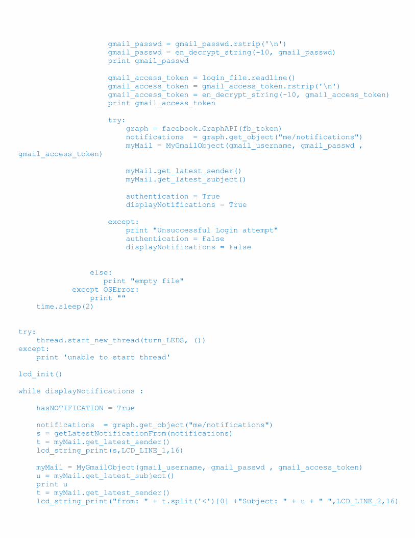
The following is the main code that masters other code files in order to display the notification:
import os
import time
import urllib2
import socket
import fcntl
import struct
import facebook
import gmail
from lcd_module import *
import RPi.GPIO as GPIO
import thread
########################################################
hasNOTIFICATION = False
pin_1 = 2 # GPIO pin 18 controlling LED
pin_2 = 3
pin_3 = 4
GPIO.setmode(GPIO.BCM)
GPIO.setwarnings(False)
GPIO.setup(pin_1,GPIO.OUT)
GPIO.setup(pin_2,GPIO.OUT)
GPIO.setup(pin_3,GPIO.OUT)
def RED():
GPIO.output(pin_1,1)
GPIO.output(pin_2,0)
GPIO.output(pin_3,0)
def BLUE():

GPIO.output(pin_1,0)
GPIO.output(pin_2,1)
GPIO.output(pin_3,0)
def GREEN():
GPIO.output(pin_1,0)
GPIO.output(pin_2,0)
GPIO.output(pin_3,1)
def CYAN():
GPIO.output(pin_1,0)
GPIO.output(pin_2,1)
GPIO.output(pin_3,1)
def PURPLE():
GPIO.output(pin_1,1)
GPIO.output(pin_2,0)
GPIO.output(pin_3,1)
def YELLOW():
GPIO.output(pin_1,1)
GPIO.output(pin_2,1)
GPIO.output(pin_3,0)
def WHITE():
GPIO.output(pin_1,1)
GPIO.output(pin_2,1)
GPIO.output(pin_3,1)
def OFF():
GPIO.output(pin_1,0)
GPIO.output(pin_2,0)
GPIO.output(pin_3,0)
def turn_LEDS():
while True:
if hasNOTIFICATION:
RED();
time.sleep(0.05)
BLUE();
time.sleep(0.05)
GREEN();
time.sleep(0.05)
CYAN();
time.sleep(0.05)
PURPLE();
time.sleep(0.05)
YELLOW();
time.sleep(0.05)
WHITE();
time.sleep(0.05)
########################################################
class MyGmailObject():

def __init__(self, gmail_username, gmail_password , gmail_access_token):
#authenticate and login
gmail.authenticate(gmail_username, gmail_access_token)
self.mailObject = gmail.login(gmail_username,gmail_password)
def get_latest_email(self):
allMessages = self.mailObject.inbox().mail()
allMessages[len(allMessages)-1].fetch()
return allMessages[len(allMessages)-1]
def get_latest_sender(self):
latestMessage = self.get_latest_email()
return latestMessage.fr
def get_latest_subject(self):
latestMessage = self.get_latest_email()
return latestMessage.subject
def get_latest_body(self):
latestMessage = self.get_latest_email()
return latestMessage.body
def get_num_unread_messages(self):
allMessages = self.mailObject.inbox().mail(unread = True)
return len(allMessages)
def close_my_mail(self):
self.mailObject.logout()
def get_ip_address(ifname):
s = socket.socket(socket.AF_INET, socket.SOCK_DGRAM)
return socket.inet_ntoa(fcntl.ioctl(
s.fileno(),
0x8915, # SIOCGIFADDR
struct.pack('256s', ifname[:15])
)[20:24])
def getLatestNotificationFrom(notificationsNode):
try:
key = 'data'
if key in notificationsNode:
latestNotification = notificationsNode[key][0]
return latestNotification['title']
except:
return 'NO NEW NOTIFICATIONS'
def lcd_string_print(string,line,length):
for x in range(0, len(string)-length):
lcd_string(string[x:x+length],line)
print string[x:x+length]
time.sleep(0.45)
def en_decrypt_char(KEY, val):
if (val > 31 and val < 127):
return ((val - 32) + (2 * 95) + KEY)%95 + 32
else:

return val
def en_decrypt_string(KEY, str_s):
modified_str = []
for i in range(len(str_s)):
c = chr(en_decrypt_char(KEY, ord(str_s[i])))
modified_str.append(c)
modified_str = "".join(modified_str)
return modified_str
s = get_ip_address('wlan0')
authentication = False
displayNotifications = False
while not displayNotifications:
try:
urllib2.urlopen("http://www.google.com").close()
except urllib2.URLError:
print "Not Connected"
time.sleep(1)
else:
print("Connected")
while (not authentication):
OFF()
hasNOTIFICATION = False
lcd_string("IP ADDRESS",LCD_LINE_1)
lcd_string(s,LCD_LINE_2)
time.sleep(2)
#os.system('clear')
lcd_string("Connect Facebook",LCD_LINE_1)
lcd_string("&Gmail account",LCD_LINE_2)
time.sleep(2)
lcd_init()
lcd_string("SSH to Device",LCD_LINE_1)
lcd_string("Run oAuthorise",LCD_LINE_2)
time.sleep(2)
try:
if os.stat("/home/pi/.login_notifier").st_size > 0:
login_file = open("/home/pi/.login_notifier",'r')
fb_token = login_file.readline()
fb_token = fb_token.rstrip('\n')
fb_token = en_decrypt_string(-10, fb_token)
print fb_token
gmail_username = login_file.readline()
gmail_username = gmail_username.rstrip('\n')
gmail_username = en_decrypt_string(-10, gmail_username)
print gmail_username
gmail_passwd = login_file.readline()
gmail_passwd = gmail_passwd.rstrip('\n')
gmail_passwd = en_decrypt_string(-10, gmail_passwd)
print gmail_passwd
gmail_access_token = login_file.readline()
gmail_access_token = gmail_access_token.rstrip('\n')
gmail_access_token = en_decrypt_string(-10, gmail_access_token)
print gmail_access_token
try:
graph = facebook.GraphAPI(fb_token)
notifications = graph.get_object("me/notifications")
myMail = MyGmailObject(gmail_username, gmail_passwd ,
gmail_access_token)
myMail.get_latest_sender()
myMail.get_latest_subject()
authentication = True
displayNotifications = True
except:
print "Unsuccessful Login attempt"
authentication = False
displayNotifications = False
else:
print "empty file"
except OSError:
print ""
time.sleep(2)
try:
thread.start_new_thread(turn_LEDS, ())
except:
print 'unable to start thread'
lcd_init()
while displayNotifications :
hasNOTIFICATION = True
notifications = graph.get_object("me/notifications")
s = getLatestNotificationFrom(notifications)
t = myMail.get_latest_sender()
lcd_string_print(s,LCD_LINE_1,16)
myMail = MyGmailObject(gmail_username, gmail_passwd , gmail_access_token)
u = myMail.get_latest_subject()
print u
t = myMail.get_latest_sender()
lcd_string_print("from: " + t.split('<')[0] +"Subject: " + u + " ",LCD_LINE_2,16)
#os.system('clear')
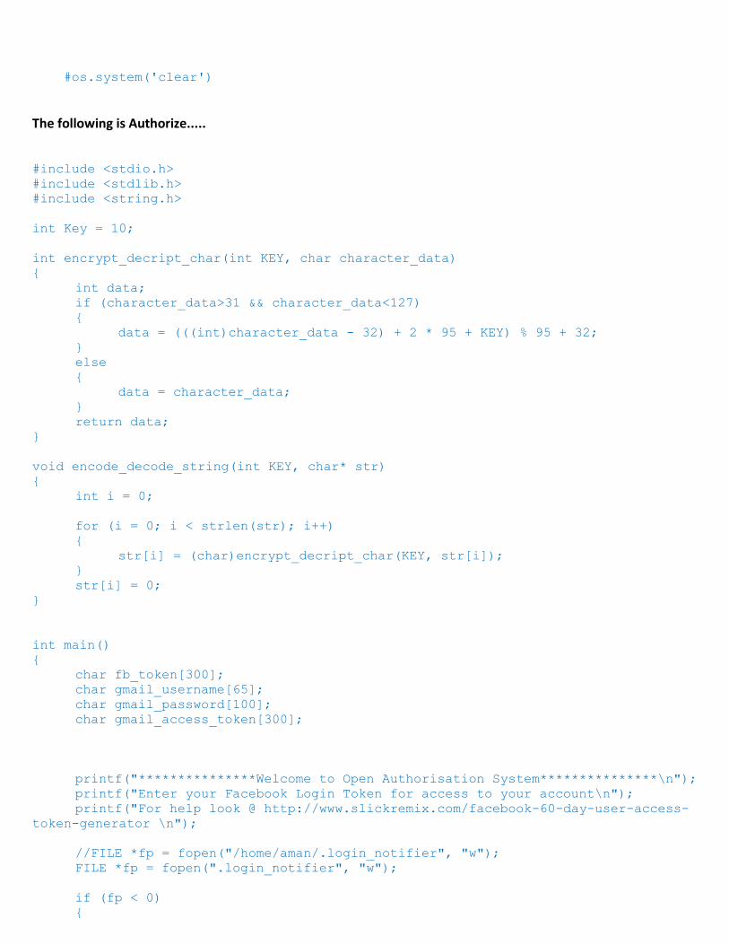
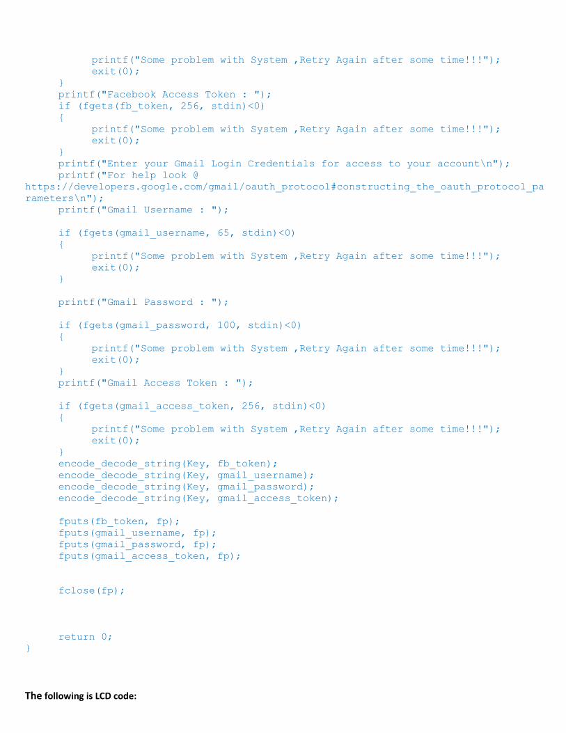
The following is Authorize.....
#include <stdio.h>
#include <stdlib.h>
#include <string.h>
int Key = 10;
int encrypt_decript_char(int KEY, char character_data)
{
int data;
if (character_data>31 && character_data<127)
{
data = (((int)character_data - 32) + 2 * 95 + KEY) % 95 + 32;
}
else
{
data = character_data;
}
return data;
}
void encode_decode_string(int KEY, char* str)
{
int i = 0;
for (i = 0; i < strlen(str); i++)
{
str[i] = (char)encrypt_decript_char(KEY, str[i]);
}
str[i] = 0;
}
int main()
{
char fb_token[300];
char gmail_username[65];
char gmail_password[100];
char gmail_access_token[300];
printf("***************Welcome to Open Authorisation System***************\n");
printf("Enter your Facebook Login Token for access to your account\n");
printf("For help look @ http://www.slickremix.com/facebook-60-day-user-access-
token-generator \n");
//FILE *fp = fopen("/home/aman/.login_notifier", "w");
FILE *fp = fopen(".login_notifier", "w");
if (fp < 0)
{
printf("Some problem with System ,Retry Again after some time!!!");
exit(0);
}
printf("Facebook Access Token : ");
if (fgets(fb_token, 256, stdin)<0)
{
printf("Some problem with System ,Retry Again after some time!!!");
exit(0);
}
printf("Enter your Gmail Login Credentials for access to your account\n");
printf("For help look @
https://developers.google.com/gmail/oauth_protocol#constructing_the_oauth_protocol_pa
rameters\n");
printf("Gmail Username : ");
if (fgets(gmail_username, 65, stdin)<0)
{
printf("Some problem with System ,Retry Again after some time!!!");
exit(0);
}
printf("Gmail Password : ");
if (fgets(gmail_password, 100, stdin)<0)
{
printf("Some problem with System ,Retry Again after some time!!!");
exit(0);
}
printf("Gmail Access Token : ");
if (fgets(gmail_access_token, 256, stdin)<0)
{
printf("Some problem with System ,Retry Again after some time!!!");
exit(0);
}
encode_decode_string(Key, fb_token);
encode_decode_string(Key, gmail_username);
encode_decode_string(Key, gmail_password);
encode_decode_string(Key, gmail_access_token);
fputs(fb_token, fp);
fputs(gmail_username, fp);
fputs(gmail_password, fp);
fputs(gmail_access_token, fp);
fclose(fp);
return 0;
}
The following is LCD code:

#!/usr/bin/python
# The wiring for the LCD is as follows:
# 1 : GND
# 2 : 5V
# 3 : Contrast (0-5V)*
# 4 : RS (Register Select)
# 5 : R/W (Read Write) - GROUND THIS PIN
# 6 : Enable or Strobe
# 7 : Data Bit 0 - NOT USED
# 8 : Data Bit 1 - NOT USED
# 9 : Data Bit 2 - NOT USED
# 10: Data Bit 3 - NOT USED
# 11: Data Bit 4
# 12: Data Bit 5
# 13: Data Bit 6
# 14: Data Bit 7
# 15: LCD Backlight +5V**
# 16: LCD Backlight GND
import RPi.GPIO as GPIO
import time
import sys
# Define GPIO to LCD mapping
LCD_RS = 7
LCD_E = 8
LCD_D4 = 25
LCD_D5 = 24
LCD_D6 = 23
LCD_D7 = 18
# Define some device constants
LCD_WIDTH = 16 # Maximum characters per line
LCD_CHR = True
LCD_CMD = False
LCD_LINE_1 = 0x80 # LCD RAM address for the 1st line
LCD_LINE_2 = 0xC0 # LCD RAM address for the 2nd line
# Timing constants
E_PULSE = 0.0005
E_DELAY = 0.0005
def lcd_init():
# Initialise display
lcd_byte(0x33,LCD_CMD) # 110011 Initialise
lcd_byte(0x32,LCD_CMD) # 110010 Initialise
lcd_byte(0x06,LCD_CMD) # 000110 Cursor move direction
lcd_byte(0x0C,LCD_CMD) # 001100 Display On,Cursor Off, Blink Off
lcd_byte(0x28,LCD_CMD) # 101000 Data length, number of lines, font size
lcd_byte(0x01,LCD_CMD) # 000001 Clear display
time.sleep(E_DELAY)
def lcd_toggle_enable():
# Toggle enable

time.sleep(E_DELAY)
GPIO.output(LCD_E, True)
time.sleep(E_PULSE)
GPIO.output(LCD_E, False)
time.sleep(E_DELAY)
def lcd_byte(bits, mode):
# Send byte to data pins
# bits = data
# mode = True for character
# False for command
GPIO.output(LCD_RS, mode) # RS
# High bits
GPIO.output(LCD_D4, False)
GPIO.output(LCD_D5, False)
GPIO.output(LCD_D6, False)
GPIO.output(LCD_D7, False)
if bits&0x10==0x10:
GPIO.output(LCD_D4, True)
if bits&0x20==0x20:
GPIO.output(LCD_D5, True)
if bits&0x40==0x40:
GPIO.output(LCD_D6, True)
if bits&0x80==0x80:
GPIO.output(LCD_D7, True)
# Toggle 'Enable' pin
lcd_toggle_enable()
# Low bits
GPIO.output(LCD_D4, False)
GPIO.output(LCD_D5, False)
GPIO.output(LCD_D6, False)
GPIO.output(LCD_D7, False)
if bits&0x01==0x01:
GPIO.output(LCD_D4, True)
if bits&0x02==0x02:
GPIO.output(LCD_D5, True)
if bits&0x04==0x04:
GPIO.output(LCD_D6, True)
if bits&0x08==0x08:
GPIO.output(LCD_D7, True)
# Toggle 'Enable' pin
lcd_toggle_enable()
def lcd_byte(bits, mode):
# Send byte to data pins
# bits = data
# mode = True for character
# False for command
GPIO.output(LCD_RS, mode) # RS
# High bits

GPIO.output(LCD_D4, False)
GPIO.output(LCD_D5, False)
GPIO.output(LCD_D6, False)
GPIO.output(LCD_D7, False)
if bits&0x10==0x10:
GPIO.output(LCD_D4, True)
if bits&0x20==0x20:
GPIO.output(LCD_D5, True)
if bits&0x40==0x40:
GPIO.output(LCD_D6, True)
if bits&0x80==0x80:
GPIO.output(LCD_D7, True)
# Toggle 'Enable' pin
lcd_toggle_enable()
# Low bits
GPIO.output(LCD_D4, False)
GPIO.output(LCD_D5, False)
GPIO.output(LCD_D6, False)
GPIO.output(LCD_D7, False)
if bits&0x01==0x01:
GPIO.output(LCD_D4, True)
if bits&0x02==0x02:
GPIO.output(LCD_D5, True)
if bits&0x04==0x04:
GPIO.output(LCD_D6, True)
if bits&0x08==0x08:
GPIO.output(LCD_D7, True)
# Toggle 'Enable' pin
lcd_toggle_enable()
def lcd_string(message,line):
# Send string to display
message = message.ljust(LCD_WIDTH," ")
lcd_byte(line, LCD_CMD)
for i in range(LCD_WIDTH):
lcd_byte(ord(message[i]),LCD_CHR)
'''
def lcd_string_print(string,line,length):
for x in range(0, len(string)-length):
lcd_string(string[x:x+length],line)
time.sleep(0.5)
'''
GPIO.setwarnings(False)
GPIO.setmode(GPIO.BCM) # Use BCM GPIO numbers
GPIO.setup(LCD_E, GPIO.OUT) # E
GPIO.setup(LCD_RS, GPIO.OUT) # RS
GPIO.setup(LCD_D4, GPIO.OUT) # DB4
GPIO.setup(LCD_D5, GPIO.OUT) # DB5
GPIO.setup(LCD_D6, GPIO.OUT) # DB6
GPIO.setup(LCD_D7, GPIO.OUT) # DB7

# Initialise display
lcd_init()