level measurement based on archimedes’ principle ... · level meter based on archimedes’...
TRANSCRIPT

Seite 1 von 22
Level Measurement based on Archimedes’ Principle
BA
Installation and Operating Instructions
Heinrichs Messtechnik Montage- und Betriebsanleitung BA
Seite 2 von 22
Contends 1 IDENTIFICATION ............................................................................................................................................................. 4
1.1 Supplier/manufacturer ................................................................................................................................................... 4
1.2 Product type .................................................................................................................................................................. 4
1.3 Product name................................................................................................................................................................ 4
1.4 Issue date ..................................................................................................................................................................... 4
1.5 Version no. .................................................................................................................................................................... 4 2 APPLICATIONS..………………………………………………………………………………………………………………………4 3 OPERATIONAL MODE AND SYSTEM DESIGN ............................................................................................................. 4
3.1 Level measurement in the container .............................................................................................................................. 4
3.2 Level measurement in the displacement vessel ............................................................................................................ 4 4 INPUT .............................................................................................................................................................................. 5
4.1 Measured variable ........................................................................................................................................................ 5
4.2 Measuring range (lower-range and upper-range value) ................................................................................................. 5 5 OUTPUT .......................................................................................................................................................................... 5
5.1 Binary output ................................................................................................................................................................. 5
5.1.1 KEI 1 or KEI 2 limit switches ............................................................................................................................... 5
5.1.2 KEM 1 or KEM 2 limit switches (special version) ................................................................................................ 5
5.2 Analog output with the ES magneto-electric transmitter................................................................................................. 5 6 CHARACTERISTIC VALUES .......................................................................................................................................... 5
6.1 Accuracy ....................................................................................................................................................................... 5
6.1.1 Measured error ................................................................................................................................................... 5
6.1.2 Repeatability ...................................................................................................................................................... 5
6.2 Influence of ambient temperature .................................................................................................................................. 5
6.3 Influence of fluid temperature ........................................................................................................................................ 5 7 CONDITIONS OF USE ..................................................................................................................................................... 6
7.1 Mounting requirements ................................................................................................................................................. 6
7.1.1 Device settings ................................................................................................................................................... 6
7.1.2 Adjusting the limit transducers ............................................................................................................................ 6
7.1.3 Use in hazardous areas ...................................................................................................................................... 7
7.2 Ambient conditions ........................................................................................................................................................ 8
7.2.1 Ambient temperature ranges .............................................................................................................................. 8
7.2.2 Storage temperature .......................................................................................................................................... 8
7.2.3 Climatic category ................................................................................................................................................ 8
7.2.4 Degree of protection ........................................................................................................................................... 8
7.2.5 Shock resistance/vibration resistance ................................................................................................................. 8
7.2.6 Electromagnetic compatibility ............................................................................................................................. 8
7.3 Fluid conditions ............................................................................................................................................................. 8
7.4 Fluid temperature limit ................................................................................................................................................... 8
7.4.1 Installation on a container ................................................................................................................................... 8
7.4.2 Installation on a displacement vessel.................................................................................................................. 8 8 CONSTRUCTION DETAILS ................................................................................................................................................ 9
8.1 Type of construction/dimensions ................................................................................................................................... 9
8.1.1 Aluminum indicator housing ................................................................................................................................ 9
8.1.2 Indicator housing made of stainless steel ......................................................................................................... 10
8.2 Weight ........................................................................................................................................................................ 11
Heinrichs Messtechnik BA Installation and Operating Instructions
Page 3 of 22
9 ELECTRICAL CONNECTION .........................................................................................................................................11
9.1 Wiring diagram for ES transmitter with 4-20 mA output ............................................................................................... 11
9.2 Wiring diagram for ES transmitter with 4-20 mA output and 2 limit switches ................................................................ 12
9.3 Wiring diagram for ES transmitter with 4-20 mA output, ppilse output and limit switch ................................................. 12
9.4 Wiring diagram for inductive limit switches KEI ............................................................................................................ 13
9.5 Wiring diagram for KEM 1 and KEM 2 micro switches ................................................................................................ 13 10 INDICATOR UNIT ...........................................................................................................................................................14 11 AUXILIARY POWER .......................................................................................................................................................14 12 CE MARK........................................................................................................................................................................14 13 ORDER INFORMATION .................................................................................................................................................14 14 SAFETY INSTRUCTIONS ...............................................................................................................................................14
14.1 Intended use ............................................................................................................................................................... 14
14.2 Installation, start-up and operating personnel .............................................................................................................. 14 15 PACKAGING, MOUNTING AND SHIPMENT ..................................................................................................................14 16 MAINTENANCE ..............................................................................................................................................................15 17 TROUBLE SHOOTING ...................................................................................................................................................15 18 RETURNING DEVICES FOR REPAIR AND SERVICE ...................................................................................................15 19 REPLACEMENT PARTS ................................................................................................................................................15 20 EXPLODED VIEWS ........................................................................................................................................................16
20.1 Aluminum indicator unit ............................................................................................................................................... 16
20.1.1 Complete indicator unit with local scale ........................................................................................................... 16
20.1.2 Complete indicator unit with 1 pc limit switch SJ 3,5-N .................................................................................... 16
20.1.3 Complete indicator unit with 2 pcs limit switches SJ 3,5N ................................................................................ 16
20.1.4 Complete indicator unit with 1 pc SPDT micro switch KEM ............................................................................ 17
20.1.5 Complete indicator unit with 2 pcs SPDT micro switches KEM ....................................................................... 17
20.1.6 Complete Indicator unit with transmitter ES Ex HART ................................................................................... 17 21 DECONTAMINATION CERTIFICATE FOR DEVICE CLEANING ...................................................................................18 22 DECLARATION OF CONFORMITY ................................................................................................................................19 23 SALES REPRESENTATIVES .........................................................................................................................................22 24 NOTES ............................................................................................................................................................................22

Heinrichs Messtechnik BA Installation and Operating Instructions
Page 4 of 22
Introduction These Installation and Operating Instructions serve as a tool for the correct installation, operation and maintenance of the device. Read the manual carefully before the device is installed and put into use. It does not include special versions or applications. All devices are thoroughly checked for order compliance and operability before delivery. Upon receipt, please conduct a visual inspection of possible damage that may be identified as having occurred during shipment. If you discover any defect, please contact our head office in Cologne or the local sales office responsible for your area (see the telephone directory at the end of this manual or on our Web site). Apart from a description of the error, we will need the equipment type and serial number of the delivery. Heinrichs Messtechnik shall not furnish guarantee for any repair work done without prior notice. Unless otherwise agreed on, the rejected parts must be made available to us in case a claim is made.
1 Identification
1.1 Supplier/manufacturer Heinrichs Messtechnik GmbH Robert-Perthel-Str. 9 D-50739 Köln Phone +49 (221) 49708 - 0 Fax +49 (221) 49708 - 178 Internet: http://www.heinrichs.eu/ E-mail: mailto:[email protected]
1.2 Product type Level meter based on Archimedes’ principle with magnetic measured-value transmission and local level display.
1.3 Product name BA
1.4 Issue date 01.02.2020
1.5 Version no. 8.0 File: BA_BA_20.01_en
2 Applications The BA-type level indicator is suitable for level measurement of liquid products in open containers and in containers under pressure. The device is based on Archimedes’ principle. The length of the displacer rod corresponds to the measuring range.
3 Operational mode and system design
The displacer rod, which is attached to a measuring spring using a chain, immerses into the liquid and is subject to a buoyant force proportional to the mass of the displaced liquid. Every change in the weight of the rod corresponds to a change in the length of the spring and is therefore a measure of the liquid level. The longitudinal expansion of the spring, i.e. the travel of the rod, will be transmitted from the measuring space to the indicator unit by means of a magnetic coupling. The basic version of the indicator unit
consists of a scale with a pointer for displaying the liquid level. As an option, the indicator unit may be equipped with electrical transmitters for remote display or with limit transducers. If the device cannot be installed from above, because, for example, a stirrer is mounted in the container, a special displacement vessel is available for lateral installation. Since the buoyancy of the displacer rod depends on the density of the measured medium, it must have been designed for the specific liquid to be measured. The difference in density between the tank atmosphere and the liquid to be measured should be at least 100 g/l. The pressure and the temperature of the atmosphere must be known.
3.1 Level measurement in the container
1 = Displacer rod L = Length of displacer rod
3.2 Level measurement in the displacement vessel
Heinrichs Messtechnik BA Installation and Operating Instructions
Page 5 of 22
4 Input
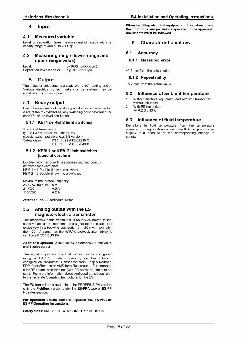
4.1 Measured variable Level or separation layer measurement of liquids within a density range of 400 g/l to 2000 g/l
4.2 Measuring range (lower-range and upper-range value)
Level: 0–100% (0–XXX cm) Separation layer indicator: e.g. 800–1100 g/l
5 Output The indicator unit contains a scale with a 90° reading angle. Various electrical contact makers or transmitters may be installed in the indicator unit.
5.1 Binary output Using the segments of the slot-type initiators or the eccentric discs of the microswitches, any switching point between 10% and 90% of the level can be set.
5.1.1 KEI 1 or KEI 2 limit switches
1 or 2 limit transducers, type SJ 3,5N, make Pepperl+Fuchs (special switch possible, e.g. SN version) Safety class: PTB Nr. 99 ATEX 2219 X PTB Nr. 00 ATEX 2048 X
5.1.2 KEM 1 or KEM 2 limit switches (special version)
Double-throw micro switches whose switching point is activated by a cam plate. KEM 1 = 1 Double-throw micros witch KEM 2 = 2 Double-throw micro switches Maximum make-break capacity: 230 VAC 50/60Hz 6 A 24 VDC 0.5 A 110 VDC 0.2 A Attention! No Ex-certificate switch
5.2 Analog output with the ES magneto-electric transmitter
The magneto-electric transmitter is factory-calibrated to the scale values upon shipment. The signal output is supplied exclusively in a two-wire connection at 4-20 mA. Normally, the 4-20 mA signal has the HART protocol; alternatively it can have PROFIBUS PA. Additional options: 2 limit values, alternatively 1 limit value and 1 pulse output The signal output and the limit values can be configured using a HART modem operating on the following configuration programs: SensorPort from Bopp & Reuther, PDM from Siemens or AMS from Rosemount. Furthermore, a HART hand-held terminal (with DD software) can also be used. For more information about configuration, please refer to the separate Operating Instructions for the ES. The ES transmitter is available in the PROFIBUS PA version or in the Fieldbus version under the ES-PPA type or ES-FF type designation. For operation details, see the separate ES, ES-PPA or ES-FF Operating Instructions. Safety class: DMT 00 ATEX 075 / II2G Ex ia IIC T6 Gb
When installing electrical equipment in hazardous areas, the conditions and provisions specified in the approval documents must be followed.
6 Characteristic values
6.1 Accuracy
6.1.1 Measured error
+/- 5 mm from the actual value
6.1.2 Repeatability
+/- 2 mm from the actual value
6.2 Influence of ambient temperature 1. Without electrical equipment and with limit transducer
without influence 2. With ES transmitter:
+/- 0.2 % / 10 K
6.3 Influence of fluid temperature Deviations in fluid temperature from the temperature observed during calibration can result in a proportional display fault because of the corresponding change in density.

Heinrichs Messtechnik BA Installation and Operating Instructions
Page 6 of 22
7 Conditions of use
7.1 Mounting requirements The mounting location must be suitable for vertical installation from above. The connection size of the meter and that of the flange of the container or the displacement vessel must be identical. The pressure stages of the flanges must coincide. The surface roughness of the flange sealing surface must be suitable for the prescribed gaskets. The gaskets must be suitable for the pressure, the temperature and the corrosion of measured medium. If the container is empty, the distance between the displacer rod and the container bottom should be 20 mm. If the device is used as a separation layer indicator, the arrangement should be such that the displacer rod will be immersed into the liquid at any time. The limit values for temperature and air humidity at the mounting location must be maintained and corrosive atmospheres must be avoided. In order to avoid a negative impact on magnetic measure-value transmission, make sure that there is adequate clearance from parts that might cause magnetic interferences such as solenoid valves and ferromagnetic components such as steel brackets/supports. The minimum lateral clearance for interfering steel parts should be 200 mm. Select the mounting location so as to enable a reliable reading of the scale values. Please take note of the space requirements for any possible disassembly of the device as well. The length of the displacer rod must also be considered. The device should not be installed close to filling tubes and stirrers.
7.1.1 Device settings
The measuring equipment is delivered ready for operation according to your order specifications. The limit transducers are set to the desired values. If you have submitted no requirements, the basic setting for 1 contact device: - Minimum contact switching point at 10% of descending level (damped/closed-circuit principle). 2 contact devices: Minimum contact switching point at 10% of descending level and maximum contact switching point at 90% of rising level.
7.1.2 Adjusting the limit switches
7.1.2.1 Inductive limit switch KEI The contacts are adjustable through the contact position indicators located on the scale. Dismantle the indicator cover, unfasten the contact position indicators, set to the desired value and reattach them. - Unscrew 4 screws of the front cover and lift off the
cover. - Do not remove the scale ! - Unfasten 2 locking screws (3) of the red limit switch
indicator (2). - Move the red switch indicator to the desired switch
point on the scale and tighten the locking screws (3) again.
- Mount the cover and tighten it´s four screws again.
1 Pointer 2 Limit switch indicator (fig. MIN) 3 Limit switch indicator locking srews 4 Locking screws switching disc 5 Single switching disc KEI
Heinrichs Messtechnik BA Installation and Operating Instructions
Page 7 of 22
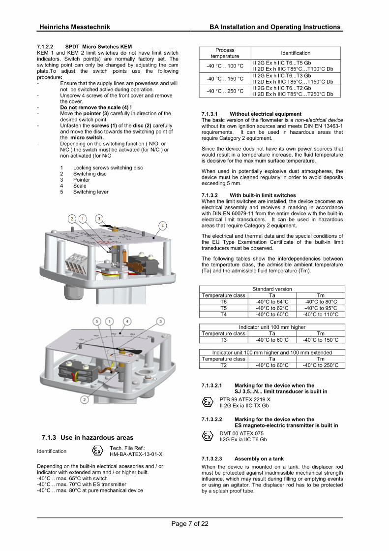
7.1.2.2 SPDT Micro Swtches KEM �E� 1 a�d �E� 2 i�it switches d� ��t have i�it switch i�dicat�rs� Switch p�i�t(s) are ��r�ay fact�ry set� The switching point can only be changed by adjusting the cam plate.T� ad�ust the switch p�i�ts use the f��wi�g pr�cedure� ! E�sure that the suppy i�es are p�weress a�d wi ��t be switched active duri�g �perati��� ! Unscrew 4 screws of the front cover and remove
the cover. - Do not remove the scale (4) ! - Move the pointer (3) carefully in direction of the
desired switch point. - Unfasten the screws (1) of the disc (2) carefully
and move the disc towards the switching point of the micro switch.
- Depending on the switching function ( N/O or N/C ) the switch must be activated (for N/C ) or non activated (for N/O
1 Locking screws switching disc
2 Switching disc 3 Pointer 4 Scale 5 Switching lever
7.1.3 Use in hazardous areas
Identification
Tech. File Ref.: HM-BA-ATEX-13-01-X
Depending on the built-in electrical acessories and / or indicator with extended arm and / or higher built. -40°C .. max. 65°C with switch -40°C .. max. 70°C with ES transmitter -40°C .. max. 80°C at pure mechanical device
Process temperature
Identification
-40 °C .. 100 °C II 2G Ex h IIC T6...T5 Gb II 2D Ex h IIIC T85°C…T100°C Db
-40 °C .. 150 °C II 2G Ex h IIC T6...T3 Gb II 2D Ex h IIIC T85°C…T150°C Db
-40 °C .. 250 °C II 2G Ex h IIC T6...T2 Gb II 2D Ex h IIIC T85°C…T250°C Db
7.1.3.1 Without electrical equipment The basic version of the flowmeter is a non-electrical device without its own ignition sources and meets DIN EN 13463-1 requirements. It can be used in hazardous areas that require Category 2 equipment.
Since the device does not have its own power sources that would result in a temperature increase, the fluid temperature is decisive for the maximum surface temperature.
When used in potentially explosive dust atmospheres, the device must be cleaned regularly in order to avoid deposits exceeding 5 mm. 7.1.3.2 With built-in limit switches When the limit switches are installed, the device becomes an electrical assembly and receives a marking in accordance with DIN EN 60079-11 from the entire device with the built-in electrical limit transducers. It can be used in hazardous areas that require Category 2 equipment.
The electrical and thermal data and the special conditions of the EU Type Examination Certificate of the built-in limit transducers must be observed.
The following tables show the interdependencies between the temperature class, the admissible ambient temperature (Ta) and the admissible fluid temperature (Tm).
Standard version Temperature class Ta Tm
T6 -40°C to 64°C -40°C to 80°C T5 -40°C to 62°C -40°C to 95°C T4 -40°C to 60°C -40°C to 110°C
Indicator unit 100 mm higher
Temperature class Ta Tm T3 -40°C to 60°C -40°C to 150°C
Indicator unit 100 mm higher and 100 mm extended
Temperature class Ta Tm T2 -40°C to 60°C -40°C to 250°C
7.1.3.2.1 Marking for the device when the SJ 3,5...N... limit transducer is built in
PTB 99 ATEX 2219 X II 2G Ex ia IIC TX Gb
7.1.3.2.2 Marking for the device when the ES magneto-electric transmitter is built in
DMT 00 ATEX 075 II2G Ex ia IIC T6 Gb
7.1.3.2.3 Assembly on a tank
When the device is mounted on a tank, the displacer rod must be protected against inadmissible mechanical strength influence, which may result during filling or emptying events or using an agitator. The displacer rod has to be protected by a splash proof tube.
Heinrichs Messtechnik BA Installation and Operating Instructions
Page 8 of 22
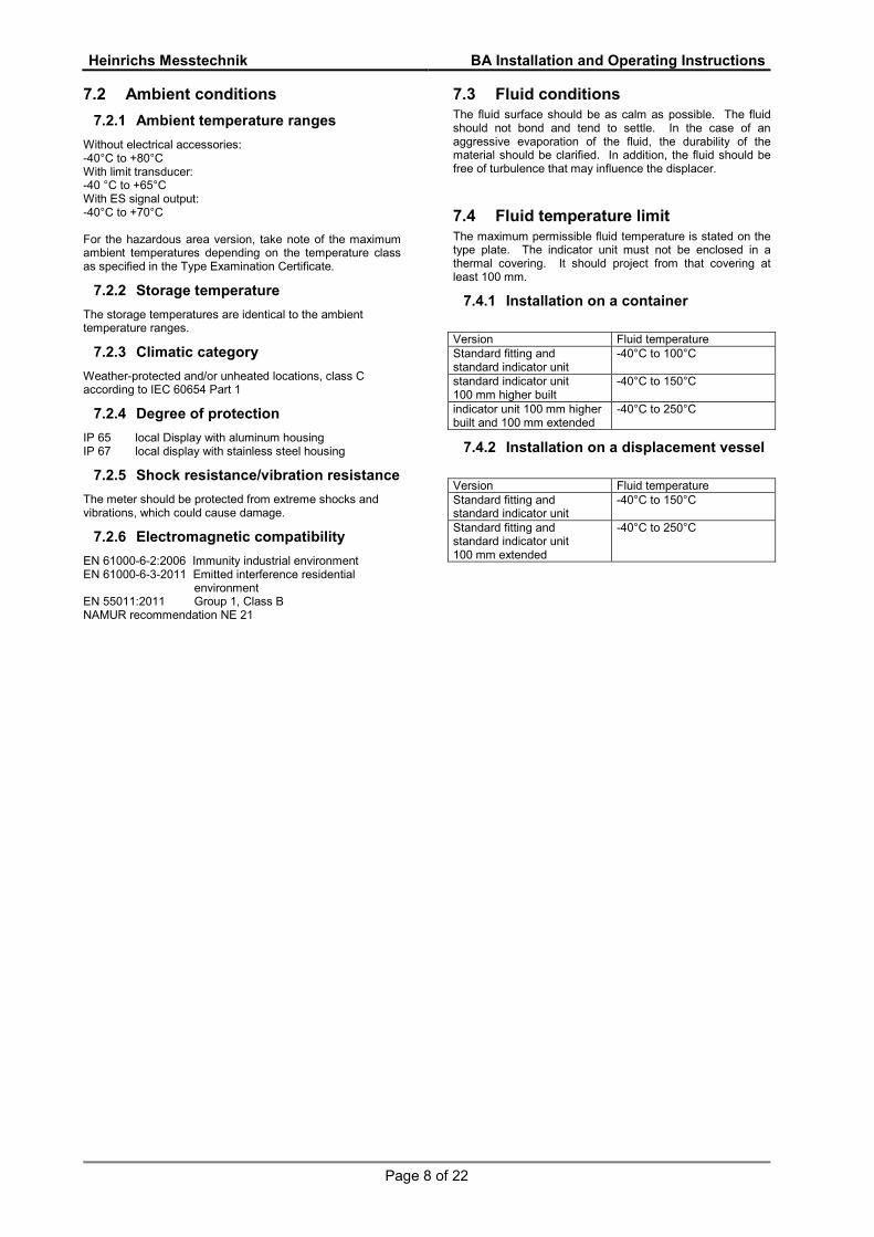
7.2 Ambient conditions
7.2.1 Ambient temperature ranges
Without electrical accessories: -40°C to +80°C With limit transducer: -40 °C to +65°C With ES signal output: -40°C to +70°C For the hazardous area version, take note of the maximum ambient temperatures depending on the temperature class as specified in the Type Examination Certificate.
7.2.2 Storage temperature
The storage temperatures are identical to the ambient temperature ranges.
7.2.3 Climatic category
Weather-protected and/or unheated locations, class C according to IEC 60654 Part 1
7.2.4 Degree of protection
IP 65 local Display with aluminum housing IP 67 local display with stainless steel housing
7.2.5 Shock resistance/vibration resistance
The meter should be protected from extreme shocks and vibrations, which could cause damage.
7.2.6 Electromagnetic compatibility
EN 61000-6-2:2006 Immunity industrial environment EN 61000-6-3-2011 Emitted interference residential environment EN 55011:2011 Group 1, Class B NAMUR recommendation NE 21
7.3 Fluid conditions The fluid surface should be as calm as possible. The fluid should not bond and tend to settle. In the case of an aggressive evaporation of the fluid, the durability of the material should be clarified. In addition, the fluid should be free of turbulence that may influence the displacer.
7.4 Fluid temperature limit The maximum permissible fluid temperature is stated on the type plate. The indicator unit must not be enclosed in a thermal covering. It should project from that covering at least 100 mm.
7.4.1 Installation on a container
Version Fluid temperature Standard fitting and standard indicator unit
-40°C to 100°C
standard indicator unit 100 mm higher built
-40°C to 150°C
indicator unit 100 mm higher built and 100 mm extended
-40°C to 250°C
7.4.2 Installation on a displacement vessel
Version Fluid temperature Standard fitting and standard indicator unit
-40°C to 150°C
Standard fitting and standard indicator unit 100 mm extended
-40°C to 250°C

Heinrichs Messtechnik BA Installation and Operating Instructions
Page 9 of 22
8 Construction details
8.1 Type of construction/dimensions
8.1.1 Aluminum indicator housing

Heinrichs Messtechnik BA Installation and Operating Instructions
Seite 10 von 22
8.1.2 Indicator housing made of stainless steel

Heinrichs Messtechnik BA Installation and Operating Instructions
Seite 11 von 22
8.2 Weight
Part Weight [kg]
Indicator unit with ES 2 Standard fitting 5.5 Fitting raised 100 mm 6.5 Displacer rod for level measurement 3 Displacer rod for separation layer measurement 3–8
9 Electrical connection Wiring To connect the auxiliary power, remove the indicator cover, insert the connector cable into the cable gland and attach it to the terminals according to terminal diagram. Tighten the cable gland securely, remount the indicator cover and close it tightly.
9.1 Wiring diagram for ES transmitter (signal output 4-20 mA with HART®)
Heinrichs Messtechnik BA Installation and Operating Instructions
Seite 12 von 22
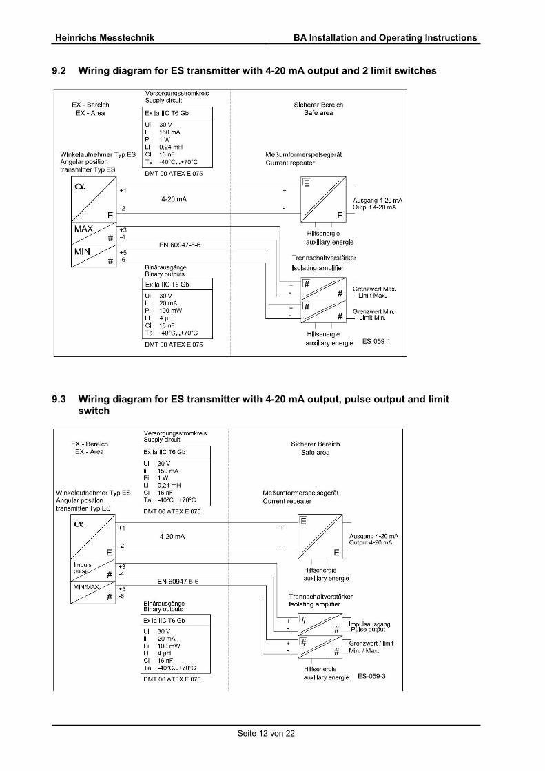
9.2 Wiring diagram for ES transmitter with 4-20 mA output and 2 limit switches
9.3 Wiring diagram for ES transmitter with 4-20 mA output, pulse output and limit switch
Heinrichs Messtechnik BA Installation and Operating Instructions
Seite 13 von 22
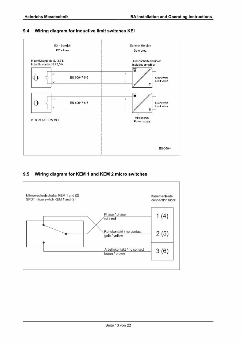
9.4 Wiring diagram for inductive limit switches KEI
9.5 Wiring diagram for KEM 1 and KEM 2 micro switches
Heinrichs Messtechnik BA Installation and Operating Instructions
Seite 14 von 22
10 Indicator unit - Analog indicator approx. 90° with pointer - Customized product scale - ES transmitter with freely programmable user interface - Parameters may be changed based on the ES
Operating Instructions.
11 Auxiliary power see Electrical connection
12 CE mark The measuring system meets the statutory requirements of the following EU directives: Directive 2014/34/EU (Equipment and Protective Systems for Use in Potentially Explosive Atmospheres), the Electromagnetic Compatibility (EMC) Directive 2014/30/EU and the Pressure Equipment Directive 2014/68/EU. Heinrichs Messtechnik confirms compliance with the directives by attaching the CE mark.
13 Order information Please include the following information in your order: With or without displacement vessel Connection size Pressure stage Flange sealing strip Material Installation from above: distance from the sealing strip
of the flange to the bottom of the container Lateral installation: flange distance to displacement
vessel Length of chain (standard version: 150 mm) Medium Density Operating temperature Operating pressure Indicator unit: standard version in “cm” (special scale
available) Additional equipment: Signal output 4-20 mA with HART with or without limit
transducer Limit transducer: 1 or 2 switching points High-temperature version: raised indicator unit High-temperature version: lateral indicator unit Special indicator unit made of stainless steel Drain, vent, plug, flange, valve (only for displacement
vessel) Separation layer version Certificates
14 Safety instructions
14.1 Intended use The BA level meter may be used only for measurements of fluid media. The manufacturer shall not be liable for damages that result from unintended or inappropriate use. When dealing with an aggressive medium, clarify the material durability of all wetted parts. When using the device in hazardous areas, follow the EC Type Examination Certificate and the applicable national installation rules.
14.2 Installation, start-up and operating personnel
Only trained specialists authorized by the system operator may carry out the installation, electrical installations, start-up, maintenance and operation. They must read and understand the operating manual and follow its instructions. The required mounting, electrical installation, start-up and maintenance work may only be carried out by expert and authorized persons designated by the plant operator. Basically, follow the conditions and provisions applicable in your country.
15 Packaging, mounting and shipment
Carefully unpack the device to avoid damaging it. Storage and installation must be done in a clean and dry room so that contamination – especially of the interior of the fitting – is avoided. Follow the limit values for ambient temperature. Carefully hang the displacer rod in its support. When transporting the device to a remote mounting location, we recommend that you reuse the factory-issued packaging and the transport protection.

Heinrichs Messtechnik BA Installation and Operating Instructions
Seite 15 von 22
16 Maintenance The device requires no maintenance if used according to its intended purpose. However, if cleaning is necessary to remove dirt from the measuring ring or the float, take note of the following aspects: - Please take note that, with devices with built-in
electrical equipment, removing the indicator cover restricts the EMC protection.
- Before removing a device, make sure that the pipeline is free from the product, is depressurized and has cooled down.
- Dirty displacer rods may be carefully cleaned after removal with a brush and the appropriate cleansing agent. Please make sure that the passage to the device head is free of sediments.
- The switching points of the limit transducers are adjustable. To do this, remove the indicator cover, unfasten the contact point indicator located on the scale and readjust it. After the adjustment, reattach the bolts of the contact point indicator. Reinstall and tighten the indicator cover.
- The parameterization of the ES is possible and is done via HART. Please refer to the separate Operating Instructions for the ES.
17 Trouble shooting - Indicator window clouds over: Water in the indicator
unit. - Indicator cover is not tight enough: Adjust the cover
seal, tighten the cover. - Window is opaque: Corrosive atmosphere, ventilate. - Window ices over due to cold and damp
atmosphere: The device can be equipped at the factory with an air/nitrogen flush.
- Window ices over due to very cold medium and damp atmosphere: The device can be equipped at the factory with a pulled-forward indicator unit.
- Device shows incorrect values: Compare the process data density and temperature with the values on the scale.
- Pointer does not react in spite of varying level: The pointer may have gotten stuck; remove the cover and move the pointer; if the pointer can be moved easily, the displacer rod cannot move. If the pointer is unable to move further, send the device to the head office for servicing.
- The displacer rod is stuck at one place due to dirt: Disassemble the device. If necessary, dismantle and clean the displacer rod.
- Scale pointer pulsates: Turbulence in the fluid or agitated fluid surface. The problem can be solved by installing a splash proof tube for the displacer rod.
- Electrical equipment are not functioning: Check the auxiliary power. Are suitable power supply equipment connected, have the terminals been selected correctly, has the parameterization carried out correctly.
18 Returning devices for repair and service
Note: In accordance with the applicable German waste disposal legislation, the owner/client is responsible for the displosal of special waste and hazardous materials. Consequently, all devices sent to us for repair must be free of any hazardous materials. This also applies to possible hollow spaces and fissures in the devices. If repair is necessary, confirm the above-mentioned item in writing (please use the form in the Appendix). If hazardous materials remain in or on the device after it has been returned, Heinrichs Messtechnik shall be authorized to remove them at the client’s expense without further inquiry.
19 Replacement parts The following parts can be ordered as replacement parts: 1 ) Indicator cover with
window/gasket/screws 2 ) Scale with standard scaling 3 ) Pointer 4 ) Magnetic transmission sleeve with pointer axis 5 ) Float/displacer rod 6 ) Limit transducer 7 ) ES transmitter
Heinrichs Messtechnik BA Installation and Operating Instructions
Seite 16 von 22
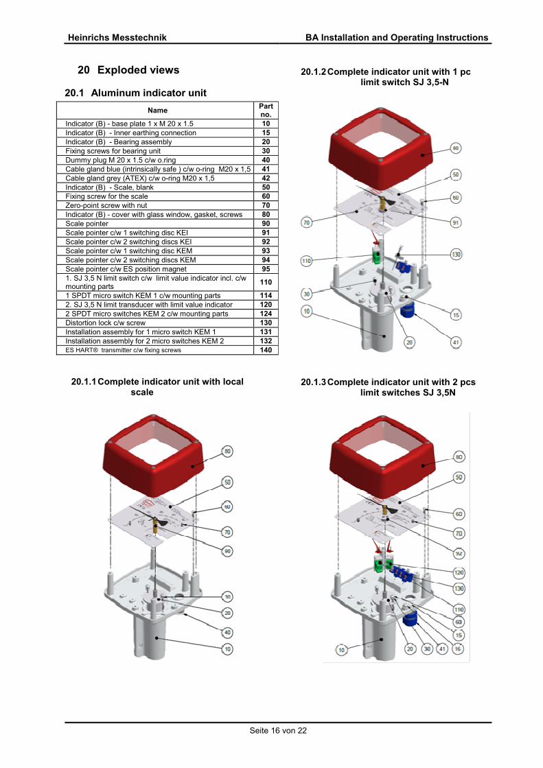
20 Exploded views
20.1 Aluminum indicator unit
Name Part no.
Indicator (B) - base plate 1 x M 20 x 1.5 10
Indicator (B) - Inner earthing connection 15
Indicator (B) - Bearing assembly 20
Fixing screws for bearing unit 30
Dummy plug M 20 x 1.5 c/w o.ring 40
Cable gland blue (intrinsically safe ) c/w o-ring M20 x 1,5 41
Cable gland grey (ATEX) c/w o-ring M20 x 1,5 42
Indicator (B) - Scale, blank 50
Fixing screw for the scale 60
Zero-point screw with nut 70
Indicator (B) - cover with glass window, gasket, screws 80
Scale pointer 90
Scale pointer c/w 1 switching disc KEI 91
Scale pointer c/w 2 switching discs KEI 92
Scale pointer c/w 1 switching disc KEM 93
Scale pointer c/w 2 switching discs KEM 94
Scale pointer c/w ES position magnet 95
1. SJ 3,5 N limit switch c/w limit value indicator incl. c/w mounting parts
110
1 SPDT micro switch KEM 1 c/w mounting parts 114
2. SJ 3,5 N limit transducer with limit value indicator 120
2 SPDT micro switches KEM 2 c/w mounting parts 124
Distortion lock c/w screw 130
Installation assembly for 1 micro switch KEM 1 131
Installation assembly for 2 micro switches KEM 2 132
ES HART® transmitter c/w fixing screws 140
20.1.1 Complete indicator unit with local . scale
20.1.2 Complete indicator unit with 1 pc . limit switch SJ 3,5-N
20.1.3 Complete indicator unit with 2 pcs . limit switches SJ 3,5N
Heinrichs Messtechnik BA Installation and Operating Instructions
Seite 17 von 22
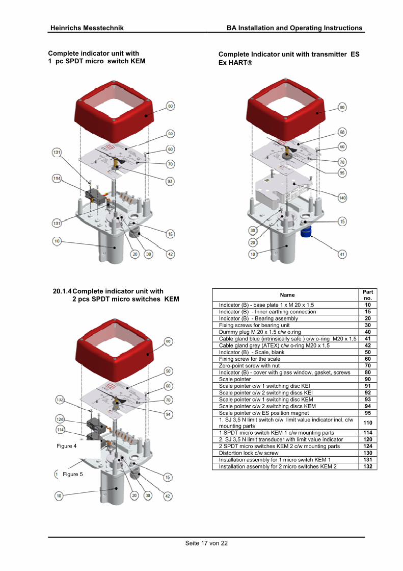
Complete indicator unit with 1 pc SPDT micro switch KEM
20.1.4 Complete indicator unit with 2 pcs SPDT micro switches KEM
Complete Indicator unit with transmitter ES
Ex HART
Name Part no.
Indicator (B) - base plate 1 x M 20 x 1.5 10
Indicator (B) - Inner earthing connection 15
Indicator (B) - Bearing assembly 20
Fixing screws for bearing unit 30
Dummy plug M 20 x 1.5 c/w o.ring 40
Cable gland blue (intrinsically safe ) c/w o-ring M20 x 1,5 41
Cable gland grey (ATEX) c/w o-ring M20 x 1,5 42
Indicator (B) - Scale, blank 50
Fixing screw for the scale 60
Zero-point screw with nut 70
Indicator (B) - cover with glass window, gasket, screws 80
Scale pointer 90
Scale pointer c/w 1 switching disc KEI 91
Scale pointer c/w 2 switching discs KEI 92
Scale pointer c/w 1 switching disc KEM 93
Scale pointer c/w 2 switching discs KEM 94
Scale pointer c/w ES position magnet 95
1. SJ 3,5 N limit switch c/w limit value indicator incl. c/w mounting parts
110
1 SPDT micro switch KEM 1 c/w mounting parts 114
2. SJ 3,5 N limit transducer with limit value indicator 120
2 SPDT micro switches KEM 2 c/w mounting parts 124
Distortion lock c/w screw 130
Installation assembly for 1 micro switch KEM 1 131
Installation assembly for 2 micro switches KEM 2 132
Figure 4
Figure 5

Heinrichs Messtechnik BA Installation and Operating Instructions
Seite 18 von 22
21 Decontamination certificate for device cleaning
Company: ............................... City: ................................... Department: ......................... Name: .............................. Tel. No.: ............................. This level meter type BA-......... with serial-no-......... was operated using the measured medium.................................................................. Since this measured medium is dangerous in water/poisonous/corrosive/flammable, we have - checked that all hollow spaces of the device are free of these materials* - neutralized and flushed all hollow spaces of the device* *cross out what is not applicable. We hereby confirm that in resending the device no danger to persons or the environment is posed by the residual measured substance. Date: ............................. Signature: ........................... Stamp
Heinrichs Messtechnik BA Installation and Operating Instructions
Seite 19 von 22
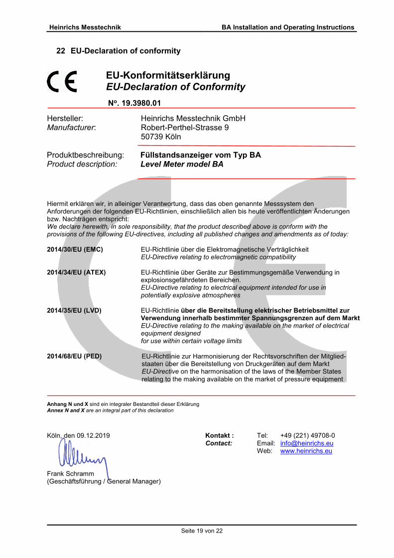
22 EU-Declaration of conformity
EU-Konformitätserklärung EU-Declaration of Conformity
No. 19.3980.01
Hersteller: Manufacturer:
Heinrichs Messtechnik GmbH Robert-Perthel-Strasse 9 50739 Köln
Produktbeschreibung: Product description:
Füllstandsanzeiger vom Typ BA Level Meter model BA
Hiermit erklären wir, in alleiniger Verantwortung, dass das oben genannte Messsystem den Anforderungen der folgenden EU-Richtlinien, einschließlich allen bis heute veröffentlichten Änderungen bzw. Nachträgen entspricht: We declare herewith, in sole responsibility, that the product described above is conform with the provisions of the following EU-directives, including all published changes and amendments as of today: 2014/30/EU (EMC) EU-Richtlinie über die Elektromagnetische Verträglichkeit
EU-Directive relating to electromagnetic compatibility
2014/34/EU (ATEX) EU-Richtlinie über Geräte zur Bestimmungsgemäße Verwendung in explosionsgefährdeten Bereichen. EU-Directive relating to electrical equipment intended for use in potentially explosive atmospheres
2014/35/EU (LVD)
EU-Richtlinie über die Bereitstellung elektrischer Betriebsmittel zur Verwendung innerhalb bestimmter Spannungsgrenzen auf dem Markt EU-Directive relating to the making available on the market of electrical equipment designed for use within certain voltage limits
2014/68/EU (PED)
EU-Richtlinie zur Harmonisierung der Rechtsvorschriften der Mitglied- staaten über die Bereitstellung von Druckgeräten auf dem Markt EU-Directive on the harmonisation of the laws of the Member States relating to the making available on the market of pressure equipment
Anhang N und X sind ein integraler Bestandteil dieser Erklärung Annex N and X are an integral part of this declaration
Köln, den 09.12.2019
Frank Schramm (Geschäftsführung / General Manager)
Kontakt : Tel: +49 (221) 49708-0 Contact: Email: [email protected] Web: www.heinrichs.eu

Heinrichs Messtechnik BA Installation and Operating Instructions
Seite 20 von 22
Anhang N zur EU-Konformitätserklärung Annex N of the EU-Declaration of Conformity
No. 19.3980.01
Produktbeschreibung: Product description:
Füllstandsanzeiger vom Typ BA Level Meter model BA
Die Konformität mit den auf Seite 1 genannten Richtlinien diese Erklärung wird nachgewiesen durch die Einhaltung folgenden Normen (abhängig von Gerätvariante): Conformity to the Directives referred to on Page 1 of this Declaration is assured through the application of the following standards (depending on version of device):
X: Zutreffende Norm / Applicable Standard
Name und Anschrift der Benannte Stelle / Name and Address of the Notified Body
TÜV-SÜD-Industrie Service GmbH TÜV SÜD Gruppe Westendstraße 199 D-80686 München ID-Nr. / ID-No.: RL 2014/68/EU: 0036
DEKRA EXAM GmbH Carl-Beyling-Haus Dinnendahlstraße 9 D-44809 Bochum ID-Nr. / ID-No.: RL 2014/34/EU: 0158
Richtlinie Direktive
Norm –Ref. Nr. Standard / Ref. No. DIN EN -
Ausgabe Edition
Norm Beschreibung Standard Description
ES
BA
2014/30/EU
61000-6-2 2011 Immunity Industrial enviroment X
61000-6-3 2012 Emission residential enviroment X
55011 2011 Radio frequency disturbance X
61326-1 2011 EMC requirements X
2014/34/EU
60079-0 2012+A11 General requirements X
60079-11 2012 Intrinsic Safety „i“ X
80079-36 2016 General requirements non-
electrical devices X
2014/35/EU 61010-1 2011 Safety requirements X
2014/68/EU AD 2000-Merkblätter Module H X

Heinrichs Messtechnik BA Installation and Operating Instructions
Seite 21 von 22
Anhang X zur EU-Konformitätserklärung Annex X of the EU-Declaration of Conformity
No. 19.3980.01
Produktbeschreibung: Product description:
Füllstandsanzeiger vom Typ BA Level Meter model BA
Gerät Zulassungen / Device certification EG-Baumusterprüfbescheinigung / Hinterlegungsnummer (1) EC-type examination certificate / accession number (1)
Nachtrag Supplement
Kennzeichnung Marking
ES
BA
DMT 00 ATEX E 075 1 II 2G X
BVS 13 ATEX H/B 005 (1) 1 II 2GD X
Tech. File Ref. - HM-BA-ATEX-13-01 X X
X: Zutreffende Norm / Applicable Standard
Konformitätserklärungen für die als Option verwendeten Schalter werden von der Hersteller auf deren Homepage bereitgestellt. For proximity switches offered as an option in conjunction with the above-mentioned products, the Declarations of Conformity are provided by the switch manufacturer on their homepage. Die oben genannten Produkte entsprechen der Richtlinie 2014/34/EU. Neue Editionen können bereits eine oder mehrere der in den jeweiligen EG-Baumusterprüfbescheinigungen genannten Normen ersetzt haben. Der Hersteller erklärt, dass alle Produkte erwähnt in dieser Konformitätserklärung auch die Anforderungen der neuen Editionen einhalten, weil die veränderten Anforderungen der neuen Editionen entweder keinen Einfluss auf das Produkt haben, oder das Produkt die Anforderungen erfüllt. The above-mentioned products comply with the Directive 2014/34/EU. New editions may have already replaced one or more of the Standards stated in the respective EC-Type-examination certificates. The manufacturer declares that all products mentioned in this Declaration of Conformity also comply with the requirements of the new editions since either the changed requirements of the new editions do not affect the product, or the product also fulfills the requirements.
Heinrichs Messtechnik GmbH
Robert-Perthel-Straße 9 50739 Köln Telefon 0221/49708-0 Telefax 0221/49708-178 http://www.heinrichs.eu [email protected]
Bankverbindung
Dresdner Bank Köln BLZ 370 800 40 Konto-Nr. 0955 051300 IBAN : DE58 3708 0040 0955 0513 00 SWIFT-BIC: DRES DE FF 370
Erfüllungsort und Gerichtsstand:
Köln Amtsgericht Köln HRA 37040 Ust.IDNr.: DE813416533 Steuer-Nr.: 217/5743/0386
Geschäftsführer
Frank Schramm

Heinrichs Messtechnik BA Installation and Operating Instructions
Seite 22 von 22
23 Sales representatives Internet: http://www.heinrichs.eu/
24 Notes