level rail instructions - the home depot · pdf filelevel rail instructions railing dynamics,...
TRANSCRIPT

LEVEL RAIL INSTRUCTIONS
RAILING DYNAMICS, INC. FOR HOME, FOR LIFE™
135 STEELMANVILLE ROAD EGG HARBOR TOWNSHIP, NJ 08234
TEL: (877) 420-7245 FAX: (866) 277-5160 E-MAIL: [email protected] URL: WWW.RDIRAIL.COM
NOTE: Check with your local building code office for design load requirements for guard rails and bottom space requirements. All supporting structures should be built in accordance with applicable building codes.

(Fig. 6)
(Fig. 7)
(Fig. 8)
2.Place bottom rail across the opening ensuring equal baluster spacing on each end (Fig. 6). Mark each end 1/4" from post face to allow for bracket thickness and expansion (Figs. 7, 8).
Transfer these marks to the top rail and cut (Figs. 9, 10).
1.Determine desired rail placement and snap a line to ensure all posts are aligned properly (Fig. 1). Make sure sufficient mounting structure exists in areas to receive posts. On wood framed installations, install blocking where necessary. Secure all posts in place and check for plum (Figs. 2, 3, 4, 5).
NOTE: Post kits include shims, mount-ing hardware sold separately.*
(Fig. 1)(Fig. 4)
(Fig. 2)
(Fig. 5)
(Fig. 3)
Tip:Post flanges are drilled to accept four 3/8" diameter fasteners. Use the appro-priate type of fastener for your instal-lation to insure post attachment meets the required loads. Check local building codes for load requirements.
(Fig. 9)
(Fig. 10)
(Fig. 12)
(Fig. 13)
(Fig. 14)
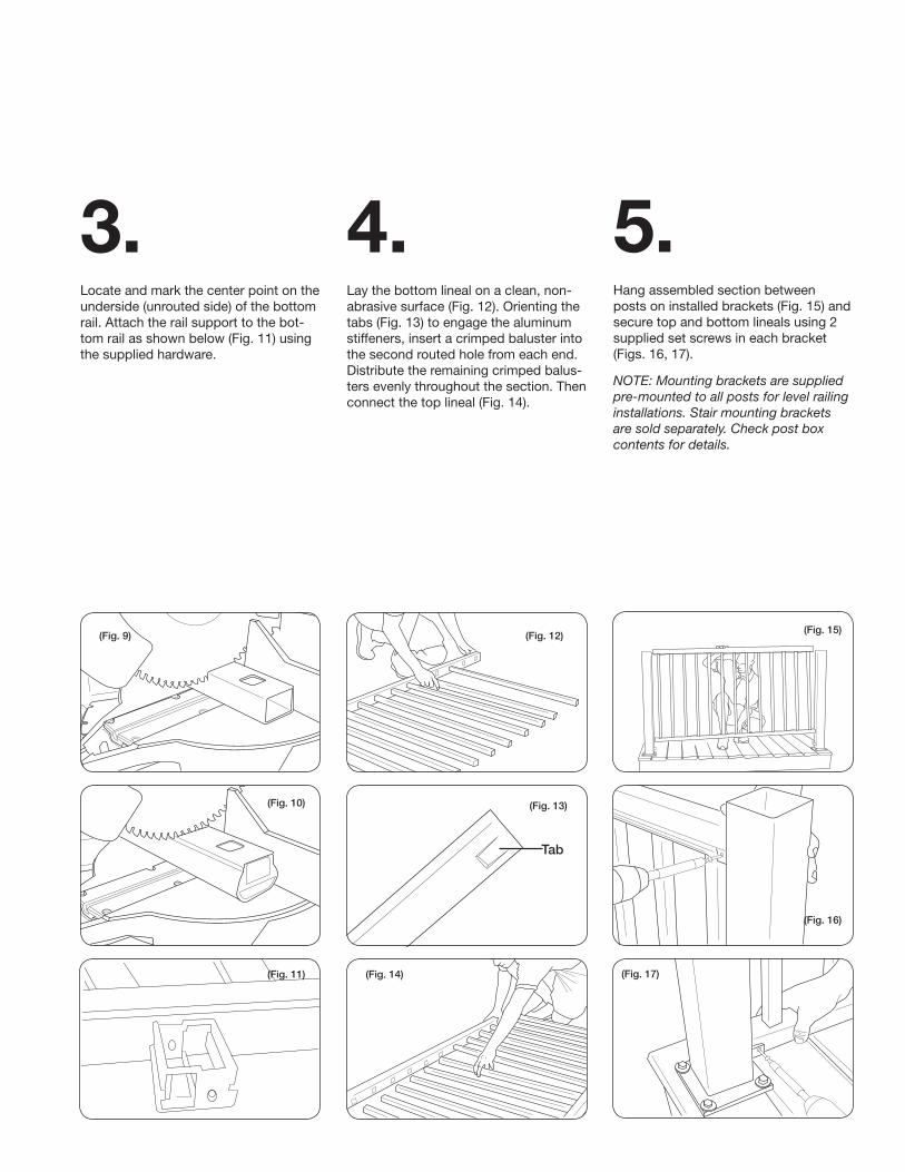
4.Lay the bottom lineal on a clean, non- abrasive surface (Fig. 12). Orienting the tabs (Fig. 13) to engage the aluminum stiffeners, insert a crimped baluster into the second routed hole from each end. Distribute the remaining crimped balus-ters evenly throughout the section. Then connect the top lineal (Fig. 14).
(Fig. 15)
(Fig. 16)
(Fig. 17)
5.Hang assembled section between posts on installed brackets (Fig. 15) and secure top and bottom lineals using 2 supplied set screws in each bracket (Figs. 16, 17).
NOTE: Mounting brackets are supplied pre-mounted to all posts for level railing installations. Stair mounting brackets are sold separately. Check post box contents for details.
Tab
3.Locate and mark the center point on the underside (unrouted side) of the bottom rail. Attach the rail support to the bot-tom rail as shown below (Fig. 11) using the supplied hardware.
(Fig. 11)

6.Install the bracket covers as shown in Figures 18 and 19. Install the 2 piece trim ring shown in Figure 20. Then glue post cap in place (Fig. 21).
(Fig. 21)(Fig. 18)
(Fig. 19)
(Fig. 20)
TMPLI 12.10MADE IN CHINA
Attach the rail support to the deck surface and snap the cover in place (Fig. 22).
(Fig. 22)