level switch catalogue - mercon.pl · 4 oil & gas bachofen ltd. has extensive experience in the...
TRANSCRIPT

Level Switch Catalogue

2
Catalogue LTKEN 2016.10, English
3www.trimodbesta.com
Worldwide in use Trimod Besta Level Switches 4
Worldwide approved Approvals 5
Quality for your safety Certificatesandtestreports 6
Modular flexibility Switch-,flange-andfloatmodules 7
Mounting combinations Numerous examples 8
Various Trimod Besta applications Application examples 9
Typical switch combinations Standard Range electric 10to handle most applications Standard Range pneumatic 14 IndustrialRange 17 Plastic Range 19
Specifying your own particular Switch modules electric 21Trimod Besta level switch ... Switch modules explosion-proof 24 Switch modules pneumatic 26 Flangemodulesstandard 27 Flange modules industrial 28 Flange modules plastic 31
Float modules 32 Rod extensions 36
... or how we can do it for you Specificationsheet 37
Accessories which save time, Counterflanges 38labour and expense Test actuators 39 Float chambers 40
Trimod Besta in hazardous areas Explosion-proof level switches 43
Electrical data to assist type selection Micro- and proximity switches 44
Table of contents
Catalogue LTKEN 2016.10, English

4
Oil & Gas
Bachofen Ltd. has extensive experience in the Offshore Industry. Some important features of the Trimod Besta product range for oil- & gas applications include stainless steel explosion-proof housings, custom-madefloatchamberdesignandNACEcompliance.
Shipbuilding TrimodBestalevelswitchesarespecifiedbytheworldsmajorship-yards and owners. Much of Bachofen’s product development and de-sign has evolved from experience within the Marine Industry such as fully submersible housings and captive terminal components. Trimod Besta level switches are registered worldwide and include LRS, DNV GL, ABS, BV, RINA and RMRS shipping approvals.
Chemical- & Petrochemical Industry
In the Chemical- and Petrochemical Industry Trimod Besta’s modular design can solve many special application problems which may re-quire high pressure, high temperature and corrosion resistant com-ponents. For measurement and control of highly aggressive or high purity media we offer a complete program of plastic switches.
Power Generation
Extreme reliability is vital in some of the applications in Power Plants. Shock and vibration resistant Trimod Besta level switches are used for critical turbine trip duties on HP/LP Heater Plants. The Quality Management System ISO 9001 and production on CNC ma-chines assure the highest product standard.
Trimod Besta Level Switches are used worldwidein many industries
Catalogue LTKEN 2016.10, English
5www.trimodbesta.com
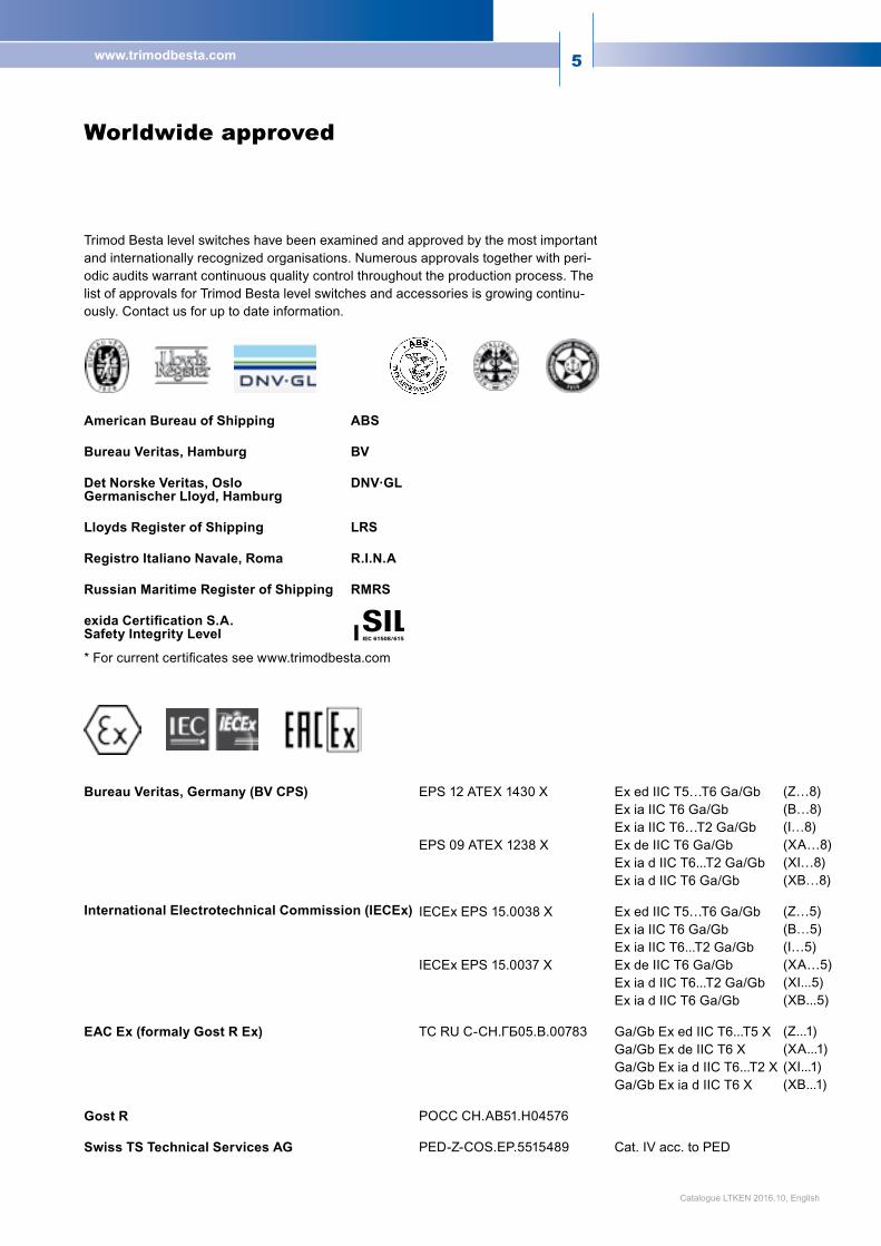
Trimod Besta level switches have been examined and approved by the most important and internationally recognized organisations. Numerous approvals together with peri-odic audits warrant continuous quality control throughout the production process. The list of approvals for Trimod Besta level switches and accessories is growing continu-ously. Contact us for up to date information.
Worldwide approved
Catalogue LTKEN 2016.10, English
American Bureau of Shipping
Bureau Veritas, Hamburg
Det Norske Veritas, OsloGermanischer Lloyd, Hamburg
Lloyds Register of Shipping
Registro Italiano Navale, Roma
Russian Maritime Register of Shipping
exida Certification S.A.Safety Integrity Level
*Forcurrentcertificatesseewww.trimodbesta.com
ABS
BV
DNV·GL
LRS
R.I.N.A
RMRS
Bureau Veritas, Germany (BV CPS)
International Electrotechnical Commission (IECEx)
EAC Ex (formaly Gost R Ex)
Gost R
Swiss TS Technical Services AG
EPS 12 ATEX 1430 X Ex ed IIC T5…T6 Ga/Gb Ex ia IIC T6 Ga/Gb Ex ia IIC T6…T2 Ga/GbEPS 09 ATEX 1238 X Ex de IIC T6 Ga/Gb Ex ia d IIC T6...T2 Ga/Gb Ex ia d IIC T6 Ga/Gb
IECEx EPS 15.0038 X Ex ed IIC T5…T6 Ga/Gb Ex ia IIC T6 Ga/Gb Ex ia IIC T6...T2 Ga/Gb IECExEPS15.0037X ExdeIICT6Ga/Gb Ex ia d IIC T6...T2 Ga/Gb Ex ia d IIC T6 Ga/Gb
TCRUC-CH.ГБ05.B.00783 Ga/GbExedIICT6...T5X Ga/Gb Ex de IIC T6 X Ga/Gb Ex ia d IIC T6...T2 X Ga/Gb Ex ia d IIC T6 X
POCCCH.AB51.H04576
PED-Z-COS.EP.5515489 Cat. IV acc. to PED
(Z…8)(B…8)(I…8)(XA…8)(XI…8)(XB…8)
(Z…5)(B…5)(I…5)(XA…5)(XI...5)(XB...5)
(Z...1)(XA...1)(XI...1)(XB...1)
6
Werkzeugnis EN 10204-2.2 T-100Test ReportRelevé de contrôle
Unsere Auftragsnummer x Ihre Bestellnummer xOur order number Your order numberNotre no. de commande Votre no. de commande
Kunde xCustomerClient
Wir bestätigen, dass die unten aufgeführten Teile aus folgenden Materialien hergestellt werden:We confirm that the following parts are manufactured of materials as follows:Nous confirmons, que les pièces suivantes sont fabriquées suit:
Bezeichnung zu Schaltertyp MaterialDescription for switch type MaterialDésignation pour type de contrôleur Matière
Rückverfolgbarkeit Bei Rückfragen ist die Angabe unserer Auftragsnummer zwingend.Traceability With queries, the indication of our order number is mandatory.
Ort, Datum Uster, UnterschriftPlace, date SignatureLieu, date Signature
FT 014; 15.10
Bachofen AG, Ackerstrasse 42, CH-8610 Uster, SwitzerlandPhone +41 44 944 11 11, Fax +41 44 944 12 [email protected], www.trimod.ch
Bescheinigung über Materialprüfungen T-101Certificate of Material TestsCertificate d'essai des matières
nach/acc. to/selon EN 10204-3.1
Unsere Auftragsnummer x Ihre Bestellnummer xOur order number Your order numberNotre no. de commande Votre no. de commande
Rückverfolgbarkeit Bei Rückfragen ist die Angabe unserer Auftragsnummer zwingend.Traceability With queries, the indication of our order number is mandatory.
Kunde xCustomerClient
In der Beilage finden Sie die Abnahmeprüfzeugnisse nach EN 10204-3.1 für die Flanschmodule der Trimod Besta Füllstandschalter.
Please find attached the Inspection Certificates according to EN 10204-3.1 for the flange modules of the Trimod Besta Level Switches.
Ci-jointvoustrouvezlesCertificates de réception selon EN 10204-3.1 pour les modules de brides des Contrôleur de niveau Trimod Besta.
Schaltertyp xSwitch typeType de contrôleur
Ort, Datum Uster, UnterschriftPlace, date SignatureLieu, date Signature
Beilagen x Abnahmeprüfzeugnisse nach EN 10204-3.1Enclosure Inspection Certificates acc. to EN 10204-3.1Annexe Certificates de réception selon EN 10204-3.1
x Zeichnung / DrawingFT 016; 15.10
Bachofen AG, Ackerstrasse 42, CH-8610 Uster, SwitzerlandPhone +41 44 944 11 11, Fax +41 44 944 12 [email protected], www.trimod.ch
Prüfprotokoll T-110Test CertificateCertificat d'essai
Unsere Auftragsnummer Ihre Bestellnummer Kunde Our order number x Your order number x Customer x Notre no. de commande Votre no. de commande Client Schaltertyp PN / Class Prüfdruck kalt hydr. bar Funktionstest elktr. Schalter Isol.-Test Funktionstest pneumatischer Schalter Switch type PN / Class Test press cold. hydr. bar Functional test electrical switch Insul. test Functional test pneumatical switch Type de contrôleur PN / Classe Press. d'épr. froide bar Test de fonct. du contôl. électr. Test d'isol. Test de fonctionnement du contrôleur pneumatique
hydraulic P-Module M-Module Dichteinheit Schwimmer Einfachschalter Dualschalter 2 kV 3-Weg-Funktion Q min. Leck max. Bereich Sealing unit Float Single switch Dual switch 3-way function Leakage max. Range Unités Flotteur Contr. simple Contr. double Fonction 3 voies Fuite max. Gamme d'étanchéité 12 bar 1.5 m³/h 1cm³/min (12bar) 0,2-1,0 bar
* * 11/14 11/12 21/24 21/22 A/C B/C A/C B/C A/C B/C
* Ausgenommen Trimod Besta Standardschalter * Trimod Besta standard switches exempt Ort, Datum Uster, Unterschrift Rückverfolgbarkeit: Bei Rückfragen ist die Angabe unserer Auftragsnummer zwingend. Place, date Signature Traceability: With queries, the indication of our order number is mandatory. Lieu, date Signature FT017;2015/10
Bachofen AG, Ackerstrasse 42, CH-8610 Uster, SwitzerlandPhone +41 44 944 11 11, Fax +41 44 944 12 [email protected], www.trimod.ch
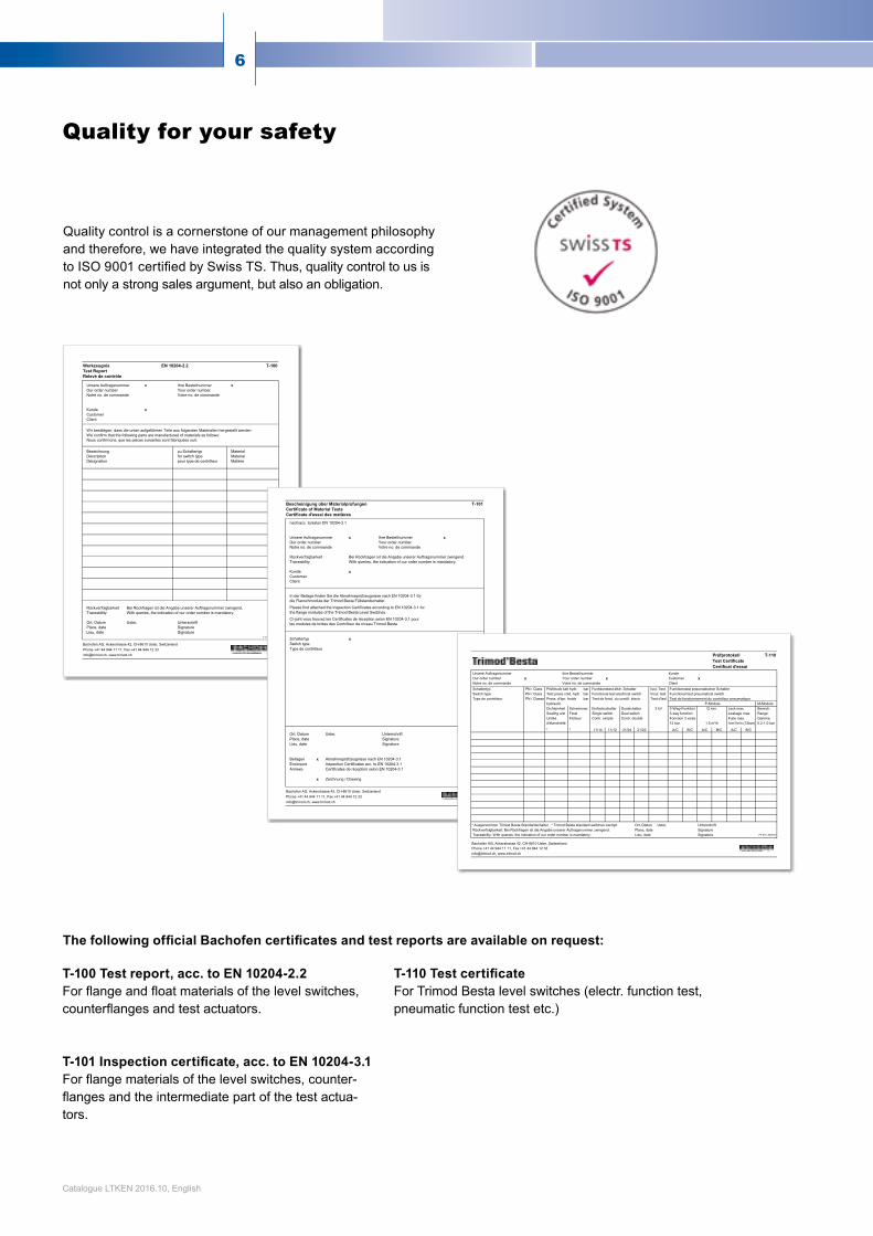
Quality control is a cornerstone of our management philosophy and therefore, we have integrated the quality system according toISO9001certifiedbySwissTS.Thus,qualitycontroltousisnot only a strong sales argument, but also an obligation.
T-100 Test report, acc. to EN 10204-2.2 Forflangeandfloatmaterialsofthelevelswitches,counterflangesandtestactuators. T-101 Inspection certificate, acc. to EN 10204-3.1 Forflangematerialsofthelevelswitches,counter-flangesandtheintermediatepartofthetestactua-tors.
T-110 Test certificate For Trimod Besta level switches (electr. function test, pneumatic function test etc.)
Quality for your safety
The following official Bachofen certificates and test reports are available on request:
Catalogue LTKEN 2016.10, English

7www.trimodbesta.com
What you need ...
Trimod Besta’s modular design is a unique deviation from conventional level switch construction. This modular system allows individual and numerous combinations of float, flange and switch modules to suit your specific requirements. Switch modules are available with electric, electronic or pneumatic output signals. Switch housings are standard to IP65 enclosure, but dependingonenvironmentalconditionsIP66,IP67orIP68mustbechosen.Forhazardous areas, hermetically sealed microswitches, flameproof housings or pneumatic switch modules can be used.
... is quickly installed ...
Trimod Besta flange modules are available in various standards. The Industrial and Plastic Flange ranges are manufactured according to international standards such as EN/DIN, ANSI, BS or JIS. The benefit of the hinged cover, the captive screws and the selflifting terminal clamps is an easy installation. For conve-nience of wiring, the connection diagram is shown on the inside of the hinged lid. The interchangeability of the single modules allows high flexibility regarding maintenance or changing application requirements.
... and lasts forever.
So far, hundreds of thousands of Trimod Besta level switches are on duty world-wide. The float movement caused by the rise and fall of the liquid level is transmitted by two repelling, permanent AINiCo magnets. The sturdy design and the double snap effect as a result of the magnetic repulsion and the snap action of the microswitch guarantee a virtually unlimited lifetime. The float modules, like all wetted parts, are made of stainless steel, Hastelloy C or high quality plastics. A wide range of floats is available to suit various viscosity-, temperature- and pressure ranges for almost any process condition.
The unique modular level switch system
Catalogue LTKEN 2016.10, English
8
01 02 03 04 05
06 07 08
16 17 18
01 06 09
02 07 10
03 08 11
04 12
05 13
14
15
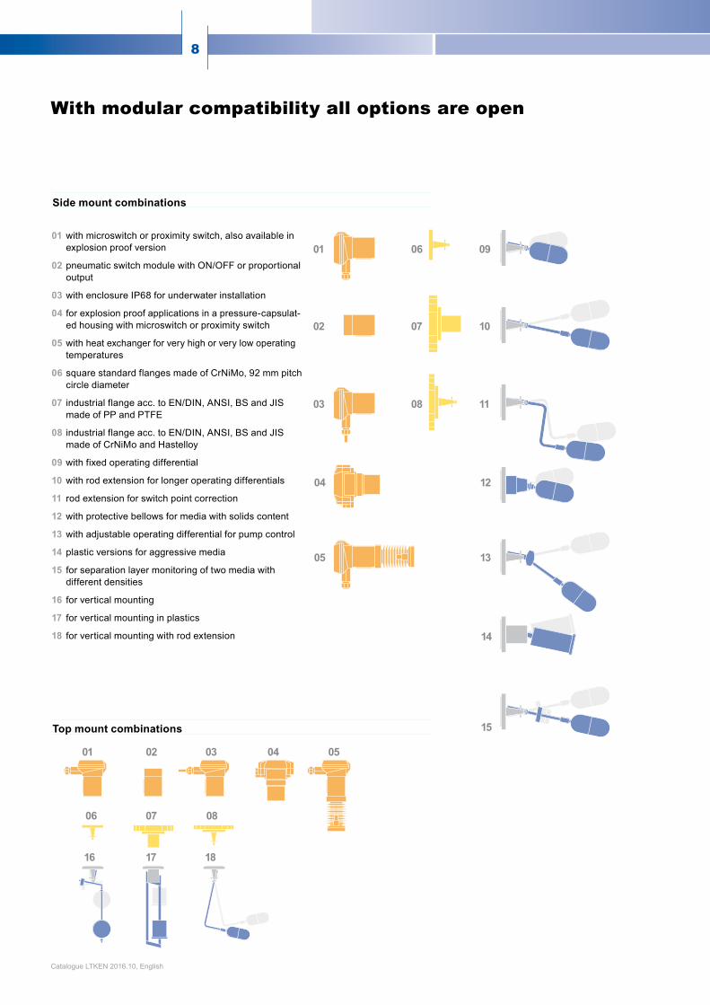
With modular compatibility all options are open
01 with microswitch or proximity switch, also available in explosion proof version
02 pneumatic switch module with ON/OFF or proportional output
03 with enclosure IP68 for underwater installation
04 for explosion proof applications in a pressure-capsulat-ed housing with microswitch or proximity switch
05 with heat exchanger for very high or very low operating temperatures
06 square standard flanges made of CrNiMo, 92 mm pitch circle diameter
07 industrial flange acc. to EN/DIN, ANSI, BS and JIS made of PP and PTFE
08 industrial flange acc. to EN/DIN, ANSI, BS and JIS made of CrNiMo and Hastelloy
09 with fixed operating differential
10 with rod extension for longer operating differentials
11 rod extension for switch point correction
12 with protective bellows for media with solids content
13 withadjustableoperatingdifferentialforpumpcontrol
14 plastic versions for aggressive media
15 for separation layer monitoring of two media with different densities
16 for vertical mounting
17 for vertical mounting in plastics
18 for vertical mounting with rod extension
Top mount combinations
Side mount combinations
Catalogue LTKEN 2016.10, English

9www.trimodbesta.com
Application examples
pump and valve control separation layer control external level control
high alarm
low alarm
max
min
pump off
pump on
pump off
pump on
high /low alarm
high /low alarm
max/min limits pneumatic control pump and valve control
Alarm, limit and control functions with Trimod Besta
Catalogue LTKEN 2016.10, English
10
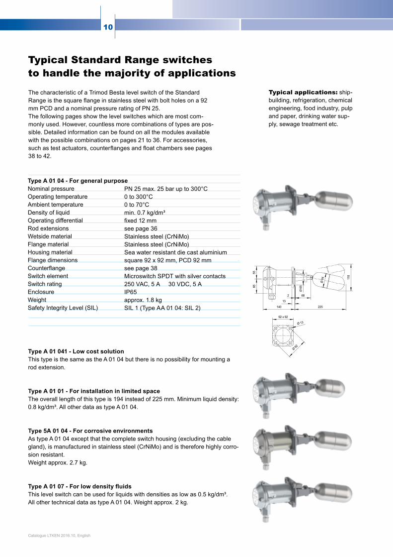
The characteristic of a Trimod Besta level switch of the Standard Rangeisthesquareflangeinstainlesssteelwithboltholesona92mm PCD and a nominal pressure rating of PN 25.The following pages show the level switches which are most com-monly used. However, countless more combinations of types are pos-sible. Detailed information can be found on all the modules available with the possible combinations on pages 21 to 36. For accessories, suchastestactuators,counterflangesandfloatchambersseepages38 to 42.
Type A 01 04 - For general purpose Nominal pressure Operating temperature Ambient temperature Density of liquid
Operating differential Rod extensions Wetside material Flange material Housing material Flange dimensions Counterflange Switch element Switch rating Enclosure Weight Safety Integrity Level (SIL)
Type A 01 041 - Low cost solution This type is the same as the A 01 04 but there is no possibility for mounting a rod extension. Type A 01 01 - For installation in limited space The overall length of this type is 194 instead of 225 mm. Minimum liquid density: 0.8 kg/dm³. All other data as type A 01 04. Type 5A 01 04 - For corrosive environments As type A 01 04 except that the complete switch housing (excluding the cable gland), is manufactured in stainless steel (CrNiMo) and is therefore highly corro-sion resistant. Weightapprox.2.7kg. Type A 01 07 - For low density fluids This level switch can be used for liquids with densities as low as 0.5 kg/dm³. All other technical data as type A 01 04. Weight approx. 2 kg.
Typical Standard Range switchesto handle the majority of applications
PN 25 max. 25 bar up to 300°C 0 to 300°C 0to70°C min.0.7kg/dm³ fixed12mm see page 36 Stainless steel (CrNiMo) Stainless steel (CrNiMo) Sea water resistant die cast aluminium square 92 x 92 mm, PCD 92 mm see page 38 Microswitch SPDT with silver contacts 250 VAC, 5 A 30 VDC, 5 A IP65 approx. 1.8 kg SIL 1 (Type AA 01 04: SIL 2)
Typical applications: ship-building, refrigeration, chemical engineering, food industry, pulp and paper, drinking water sup-ply, sewage treatment etc.
Catalogue LTKEN 2016.10, English
11www.trimodbesta.com
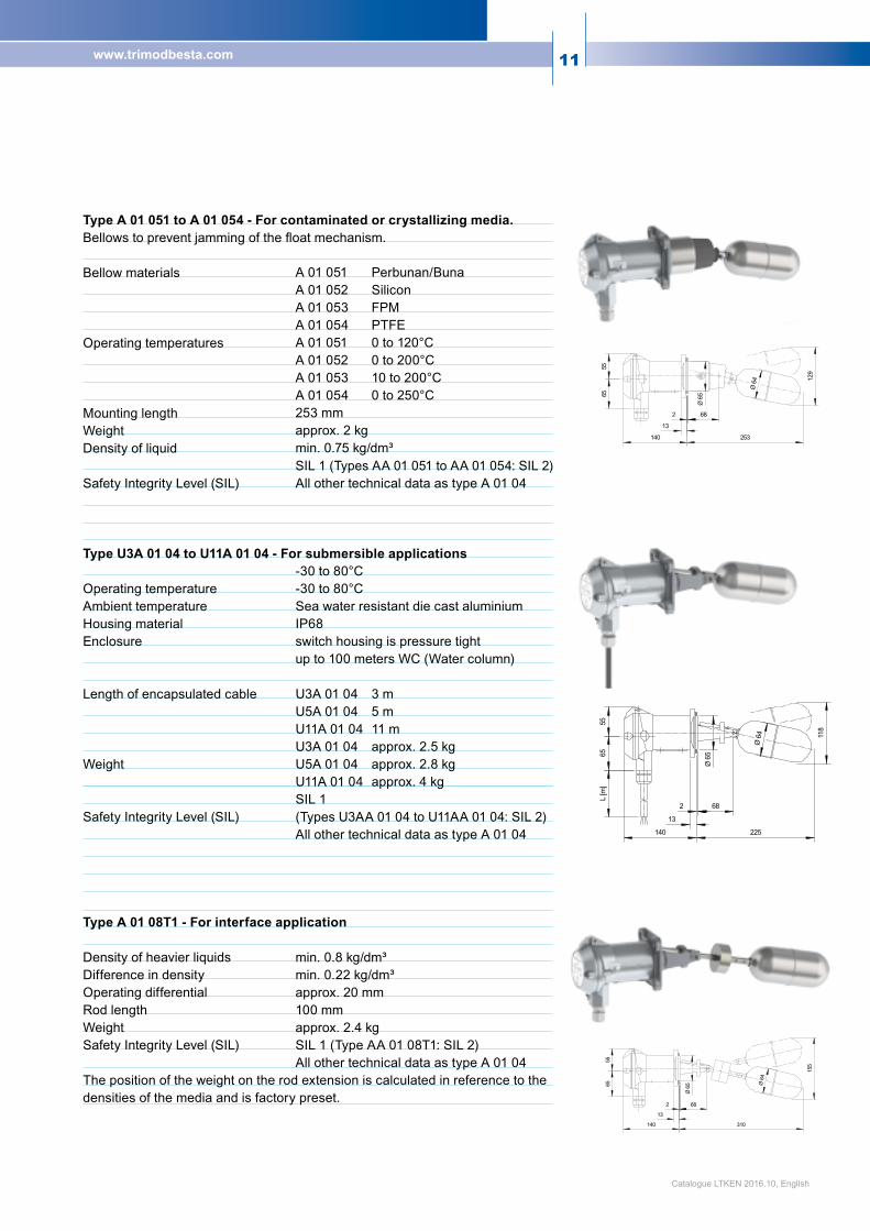
Type A 01 051 to A 01 054 - For contaminated or crystallizing media. Bellowstopreventjammingofthefloatmechanism. Bellow materials Operating temperatures Mounting length Weight Density of liquid Safety Integrity Level (SIL) Type U3A 01 04 to U11A 01 04 - For submersible applications Operating temperature Ambient temperature Housing material Enclosure Length of encapsulated cable Weight Safety Integrity Level (SIL) Type A 01 08T1 - For interface application Density of heavier liquids Difference in density Operating differential Rod length Weight Safety Integrity Level (SIL) The position of the weight on the rod extension is calculated in reference to the densities of the media and is factory preset.
A 01 051 Perbunan/Buna A 01 052 Silicon A 01 053 FPM A 01 054 PTFE A 01 051 0 to 120°C A 01 052 0 to 200°C A 01 053 10 to 200°C A 01 054 0 to 250°C 253 mm approx. 2 kg min.0.75kg/dm³ SIL 1 (Types AA 01 051 to AA 01 054: SIL 2) All other technical data as type A 01 04 -30 to 80°C -30 to 80°C Sea water resistant die cast aluminium IP68 switch housing is pressure tight up to 100 meters WC (Water column) U3A 01 04 3 m U5A 01 04 5 m U11A 01 04 11 m U3A 01 04 approx. 2.5 kg U5A 01 04 approx. 2.8 kg U11A 01 04 approx. 4 kg SIL 1 (Types U3AA 01 04 to U11AA 01 04: SIL 2) All other technical data as type A 01 04 min. 0.8 kg/dm³ min. 0.22 kg/dm³ approx. 20 mm 100 mm approx. 2.4 kg SIL 1 (Type AA 01 08T1: SIL 2) All other technical data as type A 01 04
Catalogue LTKEN 2016.10, English
12
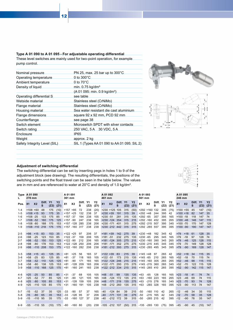
Type A 01 090 to A 01 095 - For adjustable operating differential These level switches are mainly used for two-point operation, for example pump control. Nominal pressure Operating temperature Ambient temperature Density of liquid Operating differential S Wetside material Flange material Housing material Flange dimensions Counterflange Switch element Switch rating Enclosure Weight Safety Integrity Level (SIL)
PN 25, max. 25 bar up to 300°C 0 to 300°C 0to70°C min.0.75kg/dm³ (A 01 095: min. 0.9 kg/dm³) see table Stainless steel (CrNiMo) Stainless steel (CrNiMo) Sea water resistant die cast aluminium square 92 x 92 mm, PCD 92 mm see page 38 Microswitch SPDT with silver contacts 250 VAC, 5 A 30 VDC, 5 A IP65 approx. 2 kg SIL 1 (Types AA 01 090 to AA 01 095: SIL 2)
Type A 01 090 A 01 091 A 01 092 A 01 093 A 01 095L 278 mm 361 mm 461 mm 561 mm 246 mm
Pos. X1 X2 Diff. S
Y1 (Z2)
Y2 (Z1) X1 X2 Diff.
SY1 (Z2)
Y2 (Z1) X1 X2 Diff.
SY1 (Z2)
Y2 (Z1) X1 X2 Diff.
SY1 (Z2)
Y2 (Z1) X1 X2 Diff.
SY1 (Z2)
Y2 (Z1)
1-4 +108 +60 48 175 (10) +157 +85 72 238 (20) +230 +125 105 315 (50) +292 +160 132 395 (75) +100 +55 45 147 (10)1-5 +108 +15 93 175 35 +157 +25 132 238 37 +230 +39 191 315 39 +292 +48 244 395 42 +100 +18 82 147 351-6 +108 -25 133 175 85 +157 -37 194 238 105 +230 -51 281 315 135 +292 -65 357 395 165 +100 -18 118 147 741-7 +108 -52 160 175 125 +157 -90 247 238 165 +230 -124 354 315 215 +292 -160 452 395 265 +100 -46 146 147 1151-8 +108 -80 188 175 153 +157 -128 285 238 206 +230 -171 401 315 275 +292 -215 507 395 345 +100 -70 170 147 1281-9 +108 -110 218 175 175 +157 -160 317 238 238 +230 -212 442 315 315 +292 -265 557 395 395 +100 -90 190 147 147
2-5 +98 +15 83 153 35 +122 +25 97 206 37 +181 +39 142 275 39 +230 +48 182 345 42 +79 +18 61 128 352-6 +98 -25 123 153 85 +122 -37 159 206 105 +181 -51 232 275 135 +230 -65 295 345 165 +79 -18 97 128 742-7 +98 -52 150 153 125 +122 -90 212 206 165 +181 -124 305 275 215 +230 -160 390 345 265 +79 -46 125 128 1152-8 +98 -80 178 153 153 +122 -128 250 206 206 +181 -171 352 275 275 +230 -215 445 345 345 +79 -70 149 128 1282-9 +98 -110 208 153 175 +122 -160 282 206 238 +181 -212 393 275 315 +230 -265 495 345 395 +79 -90 169 128 147
3-5 +58 +15 43 125 35 +81 +25 56 165 37 +122 +39 83 215 39 +145 +48 97 265 42 +52 +18 34 115 353-6 +58 -25 83 125 85 +81 -37 118 165 105 +122 -51 173 215 135 +145 -65 210 265 165 +52 -18 70 115 743-7 +58 -52 110 125 125 +81 -90 171 165 165 +122 -124 246 215 215 +145 -160 305 265 265 +52 -46 98 115 1153-8 +58 -80 138 125 153 +81 -128 209 165 206 +122 -171 293 215 275 +145 -215 360 265 345 +52 -70 122 115 1283-9 +58 -110 168 125 175 +81 -160 241 165 238 +122 -212 334 215 315 +145 -265 410 265 395 +52 -90 142 115 147
4-6 +25 -25 50 85 85 +31 -37 68 105 105 +48 -51 99 135 135 +63 -65 128 165 165 +23 -18 41 74 744-7 +25 -52 77 85 125 +31 -90 121 105 165 +48 -124 172 135 215 +63 -160 223 165 265 +23 -46 69 74 1154-8 +25 -80 105 85 153 +31 -128 159 105 206 +48 -171 219 135 275 +63 -215 278 165 345 +23 -70 93 74 1284-9 +25 -110 135 85 175 +31 -160 191 105 238 +48 -212 260 135 315 +63 -265 328 165 395 +23 -90 113 74 147
5-7 -15 -52 37 35 125 -33 -90 57 37 165 -40 -124 84 39 215 -50 -160 110 42 265 -12 -46 34 35 1155-8 -15 -80 65 35 153 -33 -128 95 37 206 -40 -171 131 39 275 -50 -215 165 42 345 -12 -70 58 35 1285-9 -15 -110 95 35 175 -33 -160 127 37 238 -40 -212 172 39 315 -50 -265 215 42 395 -12 -90 78 35 147
6-9 -55 -110 55 (10) 175 -80 -160 80 (20) 238 -105 -212 107 (50) 315 -135 -265 130 (75) 395 -45 -90 45 (10) 147
Catalogue LTKEN 2016.10, English
Adjustment of switching differential The switching differential can be set by inserting pegs in holes 1 to 9 of the adjustmentblock(seedrawing).Theresultingdifferentials,thepositionsoftheswitchingpointsandthefloattravelcanbeseeninthetablebelow.Thevaluesare in mm and are referenced to water at 20°C and density of 1.0 kg/dm³.

13www.trimodbesta.com
Type A 01 140 to A 01 141 - For vertical mounting Nominal pressure Operating temperature Ambient temperature Density of liquid pump control alarm Operating differential S Wetside material Flange material Housing material Flange dimensions Counterflange Switch element Switch rating Enclosure Weight Safety Integrity Level (SIL)
Setting the switching differential 1. For pump control (two switch points): Therequireddifferentialissetbyfixingthetwostopcollarsintheappropriatepositionsontherod.Thecounterweightisadjustedtocompensatefortherodweight(withoutfloat),untilthecrossarmisbalanced.Thefloatslidesupanddown the rod with the liquid level and actuates the switch at the set position of the stop collars. The switch remains latched between the two positions, which are for applica-tions such as pump control where the contactor coil would need to remain ener-gised throughout the pumping cycle. 2. For alarm duty (one switch point): Onlythelowercollarisfixedontherod(belowthefloat).Withinthelimitoftherod length, the height of the alarm point can be chosen as required. The coun-terweighthastobesettooutweightherod(withoutfloat).Thealarmswitchingdifferentialis12mm,fixed. Installation Over open tanks or sumps on a bracket. On closed tanks on the manhole cover withfloatmountedfromtheinside.Intheabsenceofamanhole,i.e.thefloatcannotbemountedfromtheinside,anintermediateflangeofatleastDN125/5″ should be used. If turbulence occurs, the rod should be guided loosely at the lower end. For counterweight setting, refer to data sheet LTDS02EN. Type U3A 01 140 to 141 - For vertical submersible mounting Operating temperature Ambient temperature Enclosure Length of cast-in cable Weight Safety Integrity Level (SIL)
PN 16, max. 16 bar up to 300°C 0 to 300°C 0to70°C 0.45 kg/dm³ 0.30 kg/dm³ A 01 140: 12 to 1340 mm A 01 141: 12 to 2840 mm Stainless steel (CrNiMo) Stainless steel (CrNiMo) Sea water resistant die cast aluminium square 92 x 92 mm, PCD 92 mm see page 38 Microswitch SPDT with silver contacts 250 VAC, 5A 30 VDC, 5A IP65 A01140:2.5kg,A01141:2.7kg SIL 1 (Types AA 01 140 to AA 01 141: SIL 2)
-30 to 80°C -30 to 80°C IP68 switch housing is pressure proof up to 100 meters WC (Water column) 3 m U3A 01 140: 3.2 kg, U3A 01 141: 3.4 kg SIL 1 (Types U3AA 01 140 to U3AA 01 141: SIL 2) All other technical data as described above
counter weight
Stop collar
Stop collar
Catalogue LTKEN 2016.10, English

14
A
C
B
A
C
B
Type P 01 04 - For pneumatic control applications Equipped with a directly controlled 3/2 way valve (ON/OFF) for control air of 0 to 10 bar. Operation with other non-corrosive gases or fluids is possible. Nominal pressure Operating temperature Ambient temperature Density of liquid
Operating differential Rod extension Control connections Max. control pressure Internal orifice Kv Factor Internal leakage rate at 10 bar Air flow Pressure drop Wetside material Flange material Housing material Counterflange Flange dimensions Weight Air quality
PN 25, max. 25 bar up to 250°C 1 to 250°C 1 to 80°C min.0.7kg/dm³ fixed 12 mm see page 36 G 1/8″ (BSPP) inside thread 10 bar 1.5 mm 1 max. 1 cm³/min 90 Nl/min at 6 bar 1 bar Stainless steel (CrNiMo) Stainless steel (CrNiMo) Sea water resistant die cast aluminium see page 38 square 92 x 92 mm, PCD 92 mm approx.1.7kg class4,ISO8571 (max. particle size 15 µm, max. particle density 8 mg/m³)
The air supply to the 3/2 way valve may be connected to either A or B, accord ing towhetherfillingoremptyingoperationisdesired or whether the actuator is normally closed or open when pressurized. E.g. pressure can be applied through A to C and exhausted from C through B, alterna-tively pressure can be applied through B to C and exhausted from C through A.
Type 5P 01 04 - For critical environments or high temperatures. All parts stainless steel. As P 01 04, but switch housing also in stainless steel (CrNiMo) and therefore, highly corrosion resistant and suitable for temperatures up to 300°C. Weight approximately 2.2 kg. Type PV 01 04 - For moist control air. As P 01 04, but with drain valve for condensate removal. Type FP 01 04 - For hazardous applications. As P 01 04, but functionally tested. With declaration of conformity for use in explosion proof areas. Type FPV 01 04 - For moist control air in hazardous applications. As FP 01 04, but with drain valve for condensate removal. With declaration of conformity for use in explosion proof areas.
Fill:
inlet air pressure max. 1.0 MPa (10 bar)
Empty:inlet air pressure max. 1.0 MPa (10 bar)
Catalogue LTKEN 2016.10, English
15www.trimodbesta.com
0
+300
1000100 200 300 400 500 600 700 800 900
+200
+100
-100
-200
-300
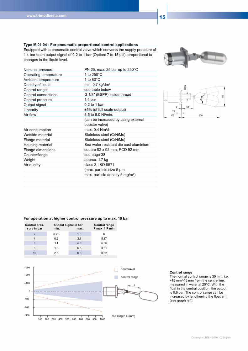
Type M 01 04 - For pneumatic proportional control applications Equipped with a pneumatic control valve which converts the supply pressure of 1.4bartoanoutputsignalof0.2to1bar(Option:7to15psi),proportionaltochanges in the liquid level. Nominal pressure Operating temperature Ambient temperature Density of liquid Control range Control connections Control pressure Output signal Linearity Airflow Air consumption Wetside material Flange material Housing material Flange dimensions Counterflange Weight Air quality
Control range The normal control range is 30 mm, i.e. +15 mm/-15 mm from the centre line, measured in water at 20°C. With the float in the central position, the output is 0.6 bar. The control range can be increased by lengthening the float arm (see graph left).
PN 25, max. 25 bar up to 250°C 1 to 250°C 1 to 80°C min.0.7kg/dm³
see table below G1/8″(BSPP)insidethread
1.4 bar 0.2 to 1 bar ±5% (of full scale output) 3.5 to 6.0 Nl/min. (can be increased by using external booster valve) max. 0.4 Nm³/h Stainless steel (CrNiMo) Stainless steel (CrNiMo) Sea water resistant die cast aluminium square 92 x 92 mm, PCD 92 mm see page 38 approx.1.7kg class3,ISO8571 (max. particle size 5 µm, max. particle density 5 mg/m³)
For operation at higher control pressure up to max. 10 bar
rod length L (mm)
control range
float travel
Control pres-sure in bar
Output signal in bar min. max.
Control rangeP max / P min
2 0.25 1.5 64 0.6 3.1 5.176 1.1 4.8 4.36
8 1.8 6.5 3.61
10 2.5 8.3 3.32
Catalogue LTKEN 2016.10, English

16
E
C
p
p
C
E
E
C
p
p
C
E
E
C
p
p
C
E
E
C
p
p
C
E
Type 5M 01 04 - For critical environments or high temperatures. All parts stainless steel. As M 01 04, but housing also in stainless steel (CrNiMo) and therefore, highly corrosion resistant and suitable for operating temperatures up to 300°C. Weight approximately 2.2 kg. Type MV 01 04 - For moist control air As M 01 04, but with drain valve for condensate removal. Type FM 01 04 - For hazardous applications As M 01 04, but functionally tested. With declaration of conformity for use in explosion proof areas. Type FMV 01 04 - For moist control air in hazardous applications As FM 01 04, but with drain valve for condensate removal. With declaration of conformity for use in explosion proof areas.
Fill:
inlet air pres-sure max. 1.4 bar
figure A figure B
Empty:
inlet aire pressure max. 1.4 bar
Control function Thestandardairconnectionconfigurationisshownhere(fig.A).Whenfilling,the output signal is decreasing proportionally to the rising level. The reverse function is obtained by turning the switch housing 180°C (seefig.B).Thiscanbeaccomplishedwithoutinterruptingtheprocess.
Catalogue LTKEN 2016.10, English

17www.trimodbesta.com
SIL 3 Capable
ThemainfeatureoftheIndustrialRangeisthewidechoiceofflangemodules,manufactured according to international standards such as EN/DIN, ANSI, BS or JIS. Available in various steel qualities, nominal sizes and pressure ratings (e.g. up to PN 320 acc. to EN/DIN or class 2500 acc. to ANSI). Shown here are only a few typical combinations, many more possibilities can be found in the module descriptions. All types in the Standard Range shown on the previous pagescanofcoursealsobecombinedwithindustrialflanges.
The Industrial Range offers numerous flange combinations
Type A 22C 04 - For general purpose Nominal pressure Operating temperature Ambient temperature Density of liquid
Operating differential Rod extension Wetside material Flange material Seal part Slip-on Flange Housing material Flange Flange facing Switch element Switch rating Enclosure Weight Safety Integrity Level (SIL) Type B 132R 07 - For low voltage circuits and low density liquids For use in low-voltage controls or logic circuits. Especially when long down-times or sulfur-containing environments are to be expected. For hazardous area see also Ex-level switches page 43. Nominal pressure Operating temperature Ambient temperature Density of liquid
Operating differential Wetside material Flange material Seal part Slip-on Flange Housing material Flange Flange facing Switch element Enclosure Weight Safety Integrity Level (SIL)
PN 40 0 to 330°C 0to70°C min.0.7kg/dm³
fixed 12 mm see page 36 Stainless steel (CrNiMo) Stainless steel (CrNiMo) Carbon steel P265GH, zinc galvanised and passivated Sea water resistant die cast aluminium DN 65, PN 40 acc. to EN 1092-1 (DIN 2501) Raised face type B1 (type C - DIN 2526) Microswitch SPDT with silver contacts 250 VAC, 5 A 30 VDC, 5 A IP65 approx. 5.4 kg SIL 1 (Type AA 22C 04: SIL 2) ANSI cl. 300 lbs 0 to 330°C 0to70°C min. 0.5 kg/dm³
fixed 12 mm Stainless steel (CrNiMo) Stainless steel (CrNiMo) Carbon steel P265GH, zinc galvanised and passivated Sea water resistant die cast aluminium DN3″,PNcl.300ANSIB16.5 Raised face Microswitch SPDT with gold plated contacts IP65 approx. 8.6 kg SIL1(TypeBB132R07:SIL2)
Frequently used on off-shore rigs, in steam boilers and plants, power stations, chemical and petrochemical engineering, heating and refrigeration, i.e. airconditioning technology.
Catalogue LTKEN 2016.10, English

18
Type HA 24E 02 - For high temperature Nominal pressure Operating temperature Ambient temperature Density of liquid Operating differential Rod extension Wetside material Flange material Seal part Slip-on Flange
Housing material Flange Flange facing Switch element Switch rating Enclosure Weight Safety Integrity Level (SIL) Type 5TDI 22CF 041 - For low temperature and severe environmental conditions Completelyinstainlesssteelwithfixedflange.ForhazardousareaseealsoEx-level switches page 43. Nominal pressure Operating temperature Ambient temperature Density of liquid Operating differential Wetside material Flange material Housing material Flange Flange facing Switch element Nominal voltage Operating voltage Current output Function For inverse function Enclosure WeightSafety Integrity Level (SIL)
PN 100 0 to 400°C 0 to 135°C min.0.7kg/dm³ fixed12mm see page 36 Stainless steel (CrNiMo)
Stainless steel (CrNiMo) Carbon steel P265GH, zinc galvanised and passivated seawater resistant, die cast aluminium DN 65, PN 100 acc. to EN 1092-1 (DIN 2501) Raised face type B2 (type E - DIN 2526) Microswitch SPDT with silver contacts 250 VAC, 5 A 30 VDC, 5 A IP65 approx. 9.6 kg SIL 1 (Type HAA 24E 02: SIL 2) PN 40 -196°Cto270°C -10°C to 80°C min.0.7kg/dm³ fixed12mm Stainless steel (CrNiMo) Stainless steel (CrNiMo) Stainless steel (CrNiMo) DN 65, PN 40 acc. to EN 1092-1 (DIN 2501) Raised face type B1 (type C - DIN 2526) Inductive proximity switch acc.toNAMUR/EN60947-5-6 8.2 VDC ±5% 5 to 25 VDC Proximityopen:≥2.2mAfloatdown Proximityclosed:≤1mAfloatup as high alarm: at closed circuitas low alarm: at operating circuitType 5TDIN 22CF 041IP66/IP67approx.7.7kgSIL 1
Catalogue LTKEN 2016.10, English

19www.trimodbesta.com
Type A 301 99 - For general use in PP Nominal pressure Operating temperature Ambient temperature Density of liquid
Operating differential Rod extension Wetside material Flange material Housing material Flange Flange facing Switch element Switch rating Enclosure Weight Type A 304 98 - For high temperature and corrosive applications in PTFE Nominal pressure Operating temperature Ambient temperature Density of liquid
Operating differential Rod extension Wetside material Flange material Housing material Flange Flange facing Switch element Switch rating Enclosure Weight
The main feature of the Plastic Range is that all wetside materials are in corro-sion resistant plastics such as PP or PTFE. Following are four typical examples, but these are by no means the limit of possible combinations which can be specifiedbyreferencetothemoduledescriptionsonpages21to35.
The Plastic Range for corrosive or high purity media
Vacuum Applications: For vacuum duty a modified sealing must be used, suffix to flange code is E20, e.g. A 301E20 99. This must be specified in the pur-chase order. The vacuum sealing unit is ca-pable of operating to 0 bar absolute pressure. Proven application areas: chemical engi-neering, electroplating, food industry, etc.
PN 10 max. 10 bar up to 25°C
max. 5 bar at 45°C max. 2.5 bar at 60°C
0 to 60°C 0 to 60°C min. 0.65 kg/dm³
fixed12mm see page 36 PP Seal part: PP Slip-on Flange: PVC Sea water resistant die cast aluminium DN 80, PN 10 acc. to EN 1092-1 (DIN 2501) Raised face type B1 (type C - DIN 2526) Microswitch SPDT with silver contacts 250 VAC, 5 A 30 VDC, 5 A IP65 approx. 1.9 kg PN 6 max. 6 bar up to 65°C max. 4.5 bar at 100°C max. 3 bar at 200°C 0 to 200°C 0to70°C min.0.75kg/dm³
fixed12mm see page 36 PTFE Seal part: PTFE 25% GRP Slip-on Flange: Carbon steel P265GH, zinc galvanised and passivated Sea water resistant die cast aluminium DN 80, PN 10 acc. to EN 1092-1 (DIN 2501) Raised face type B1 (type C - DIN 2526) Microswitch SPDT with silver contacts 250 VAC, 5 A 30 VDC, 5 A IP65 approx. 5 kg
Catalogue LTKEN 2016.10, English

20
Type A 501 97 - For vertical mounting in PP for alarm or pump control Nominal pressure Operating temperature Ambient temperature Density of liquid Operating differential S Wetside material Flange material Housing material Flange Flange facing Switch element Switch rating Enclosure Weight
PN 10 max. 10 bar up to 25°C max. 5 bar at 45°C max. 2.5 bar at 60°C 0 to 60°C 0 to 60°C min. 0.5 kg/dm³ 12to1730mm PP Seal part: PP Slip-on Flange: PVC Sea water resistant die cast aluminium DN 125, PN 10 acc. to EN 1092-1 (DIN 2501) Raised face type B1 (type C - DIN 2526) Microswitch SPDT with silver contacts 250 VAC, 5 A 30 VDC, 5 A IP65 approx. 3.1 kg
Catalogue LTKEN 2016.10, English

21www.trimodbesta.com
The switch module is selected according to the type of control required, switch-ing capability, environmental conditions and the working temperature in the vessel. The key on page 22 shows how the designation code is structured. The details of the switch modules are listed in the following tables 1 to 13. In accordance with the relevant EU-directives and where applicable, Trimod Besta level switches are marked . Table 1 Electrical/Electronic Basic Modules, IP65With 1 or 2 switches, galvanically isolated and with earthed encapsulation. En-closure type IP65. Housing in sea water resistant die cast aluminium, with cable gland M20x1.5.
Switch modules
Table 1
111412
111412
242221
111412
242221
-1114+12
-1114+12
-1114+12
-1114+12
+2422-21
111412
Type Function SIL Rating Temperature in °COperating Ambient
Connection diagram
A SPDT Microswitch with silver contacts SIL 1 250 VAC, 5 A 30 VDC, 5 A 0 to +330 0to+70
AA Dual SPDT Microswitches with silver contacts, galvanically isolated SIL 2 250 VAC, 5 A
30 VDC, 5 A 0 to +330 0to+70
B SPDT Microswitch with gold plated contacts SIL 1 0.3 A / 30 VDC 0 to +330 0to+70
BB Dual SPDT Microswitches with gold plated contacts, galvanically isolated SIL 2 0.3 A / 30 VDC 0 to +330 0to+70
I
Proximityswitchesacc.toNAMUR/EN60947-5-6. As high alarm in the quiescent current mode or as a low alarm in the working current mode. Floatup:Proximityswitchdamped:I≤1mAFloatdown:Proximityswitchundamped:I≥2.2mA
SIL 1 UN8.2 VDC ±5%(UB5 to 25 VDC) 0 to +150 0to+70
IN
Proximityswitchesacc.toNAMUR/EN60947-5-6. As low alarm in the quiescent current mode or as a high alarm in the working current mode. Floatup:Proximityswitchundamped:I≥2.2mAFloatdown:Proximityswitchdamped:I≤1mA
SIL 1 UN8.2 VDC ±5%(UB5 to 25 VDC) 0 to +150 0to+70
IIDual proximity switches acc. to NAMUR/EN 60947-5-6.High/lowlevel,galvanicallyisolated.Combination of I and IN.
SIL 1 UN8.2 VDC ±5%(UB5 to 25 VDC) 0 to +150 0to+70
IE9
Self-checking proximity switch acc. to NAMUR/EN 60947-5-6,TÜVapproved.Ashighalarminthe quiescent current mode. Floatup:proximityswitchdamped:I≤1mAFor self-checking operate in quiescent current mode.
SIL 1 UN8.2 VDC ±5%(UB5 to 25 VDC) 0 to +150 0to+70
INE9
Self-checking proximity switch acc. to NAMUR/EN 60947-5-6,TÜVapproved.Aslowalarminthe quiescent current mode. Floatdown:proximityswitchdamped:I≤1mAFor self-checking operate in quiescent current mode
SIL 1 UN8.2 VDC ±5%(UB5 to 25 VDC) 0 to +150 0to+70
IIE9
Dual self-checking proximity switches acc. to NAMUR/EN60947-5-6,TÜVapproved.High/lowlevel, galvanically isolated. Combination of IE9 and INE9.
SIL 1 UN8.2 VDC ±5%(UB5 to 25 VDC) 0 to +150 0to+70
-1114+12
-1114+12
+2422-21
Catalogue LTKEN 2016.10, English

22
Housing material coatings for enhanced requirements
Switch module (electric / electronic / pneumatic)
Increasedprotection(IP66/IP67/IP68)High or low temperature version
Switch module housing material option (chromated/complete in stainless steel CrNiMo)
Cable gland other than M20x1.5
Key to type numbers
Switch module Flange module Float modulePrefix Basic Page27 Page32 module
Thread for cable gland The types in Tables 1, 2, 4 and 5 are available on request with a cable gland thread other than M20x1.5.
Chromated housing (ROHS conform)
ThetypesinTables1,2,7and11arealsoavailablewithchromatizedhousing.Thedesignationprefixis2.ThetypesinTables3,4,5,9,and10arechromatizedasstan-dard. Example: 2DA or X2B8
All switch modules in Tables 1 to 11 are also available in stainless steel. Thedesignationprefixis5. Example: 5DA or X5A8
Most switches are available with Epoxy coating.Designationsuffix: E46 Epoxycoatinggrey E146 Epoxy coating white Example: DAE46
Stainless steel housing (CrNiMo/316SS)
Epoxy coated housing
Prefix Cable gland10 Marine execution (DIN 89280), Type W
30 Marine execution (DIN 89280), Type Z
40 Internalthread3/4″NPT(withoutcablegland)
Catalogue LTKEN 2016.10, English

23www.trimodbesta.com
Table 5 Low operating temperature All basic modules in Table 1 are also available in a low temperature version with chromatized housingIP66/IP67.ThedesignationprefixisTD. All data in Table 1, except for temperature rating and connection diagram, remain un-changed.
Table 2Increased protection enclosure IP66/IP67 All basic modules in Table 1 are also available inIP66/IP67.ThedesignationprefixisD.Alldata in Table 1, except for the temperature rat-ing remain unchanged. For high temperatures (operating -40°C to +200°C, ambient -40°C to +120°C), add E28, e.g. DAE28
Table 3 Submersible version IP68 All basic modules in Table 1 are also available for submerged applications (IP68) to 100 m depth with chromatized housing. The designa-tionprefixisU3,U5orU11.Thedesignation3,5and11specifiesstandardlengthsofen-capsulated cable in meters (longer cables are available). All data in Table 1, except for tem-perature rating, remain unchanged. Housing: chromated.
Table 4 High operating temperature All basic modules in Table 1 are also available in a high temperature version with chromatized housingIP65.ThedesignationprefixisH.Alldata in Table 1, except for temperature rating and connection diagram, remain unchanged.
Table 6 Ex-Switches for intrinsically safe circuits (Ex-i) The level switches with switch modules of types I, IE9 and B are designed also for use in hazardous areas. Technical details, see page 43. Example: IE98
Type Temperature in °COperating Ambient
DA / DAA* -30 to +120 -30 to +120DB / DBB* -30 to +120 -30 to +120DI / DIN / DII -30 to +120 -20 to +90DIE9 / DINE9 / DIIE9 -30 to +120 -30 to +90
Safety Integrity Level (SIL): all types SIL 1Types DAA / DBB: *SIL 2
Type Temperature in °COperating Ambient
U3A / U3AA* -30 to +80 -30 to +80U3B / U3BB* -30 to +80 -30 to +80U3I / U3IN / U3II -25 to +80 -25 to +80U3IE9 / U3INE9 / U3IIE9 -30 to +80 -30 to +80
Safety Integrity Level (SIL): all types SIL 1Types U3AA / U3BB: *SIL 2
Type Temperature in °COperating Ambient
HA / HAA* 0 to +400 0 to +135HB / HBB* 0 to +400 0 to +135HI / HIN / HII 0 to +300 0to+75HIE9 / HINE9 / HIIE9 0 to +300 0to+75
Safety Integrity Level (SIL): all types SIL 1Types HAA / HBB: *SIL 2
Type Temperature in °COperating Ambient
TDA / TDAA* -196to+270 -10 to +80TDB / TDBB* -196to+270 -10 to +80TDI / TDIN / TDII -196to+270 -10 to +80TDIE9 / TDINE9 / TDIIE9 -196to+270 -10 to +80
Safety Integrity Level (SIL): all types SIL 1Types TDAA / TDBB: *SIL 2
Catalogue LTKEN 2016.10, English
Approved types
Desig-nation
Type acc. to Approval authority
Classification Certificate
I... / IE9... 8 2014/34/EU BV CPS Ex ia IIC T6…T2 Ga/Gb
EPS 12 ATEX 1430 X
I... / IE9... 5 IECEx scheme
BV CPS Ex ia IIC T6...T2 Ga/Gb
IECEx EPS 15.0038 X
B... 8 2014/34/EU BV CPS Ex ia IIC T6 Ga/Gb EPS 12 ATEX 1430 X
B... 5 IECEx scheme BV CPS Ex ia IIC T6 Ga/Gb IECEx EPS 15.0038 X
24
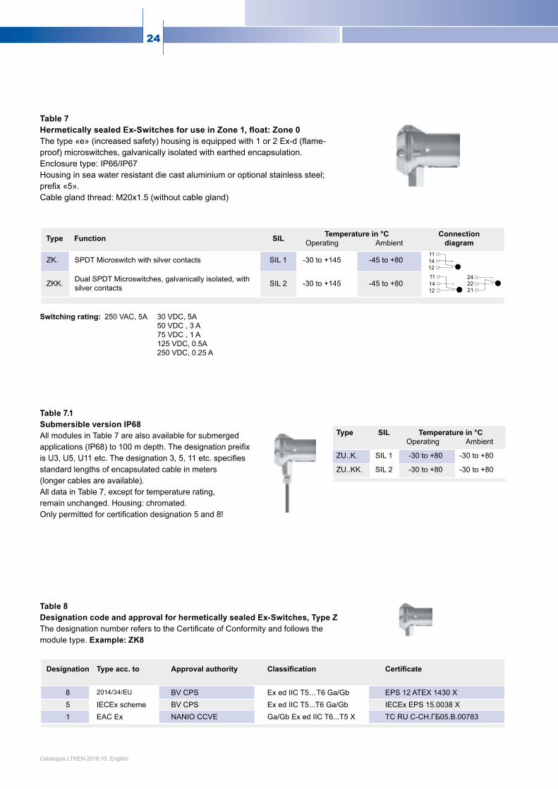
Table 7 Hermetically sealed Ex-Switches for use in Zone 1, float: Zone 0The type «e» (increased safety) housing is equipped with 1 or 2 Ex-d (flame-proof) microswitches, galvanically isolated with earthed encapsulation. Enclosuretype:IP66/IP67 Housing in sea water resistant die cast aluminium or optional stainless steel; prefix «5». Cable gland thread: M20x1.5 (without cable gland)
Table 8 Designation code and approval for hermetically sealed Ex-Switches, Type Z The designationnumberreferstotheCertificateofConformityandfollowsthemodule type. Example: ZK8
Table 7.1 Submersible version IP68AllmodulesinTable7arealsoavailableforsubmergedapplications (IP68) to 100 m depth. The designation preifix is U3, U5, U11 etc. The designation 3, 5, 11 etc. specifies standard lengths of encapsulated cable in meters (longer cables are available).AlldatainTable7,exceptfortemperaturerating,remain unchanged. Housing: chromated.Only permitted for certification designation 5 and 8!
Switching rating: 250 VAC, 5A 30 VDC, 5A 50 VDC , 3 A 75VDC,1A 125 VDC, 0.5A 250 VDC, 0.25 A
Type Function SIL Temperature in °C Operating Ambient
Connection diagram
ZK. SPDT Microswitch with silver contacts SIL 1 -30 to +145 -45 to +80
ZKK. Dual SPDT Microswitches, galvanically isolated, withsilver contacts SIL 2 -30 to +145 -45 to +80
111412
111412
242221
Designation Type acc. to Approval authority Classification Certificate
8 2014/34/EU BV CPS Ex ed IIC T5…T6 Ga/Gb EPS 12 ATEX 1430 X5 IECEx scheme BV CPS Ex ed IIC T5...T6 Ga/Gb IECEx EPS 15.0038 X1 EAC Ex NANIO CCVE Ga/Gb Ex ed IIC T6...T5 X TCRUC-CH.ГБ05.B.00783
Type SIL Temperature in °C Operating Ambient
ZU..K. SIL 1 -30 to +80 -30 to +80
ZU..KK. SIL 2 -30 to +80 -30 to +80
Catalogue LTKEN 2016.10, English

25www.trimodbesta.com
-1a
+2a3a
-1a
+2a3a
-3n
+2n-1n
Table 9 High operating temperature AllbasicmodulesinTable7arealsoavailable in a high temperature version withchromatizedhousingtoIP66/IP67.ThedesignationprefixisZHoroptionalstainlesssteel;prefixisZ5H. ConnectiondiagramseeTable7.
Table 12Designation code and approval for flame proof switchesThedesignationnumberreferstotheCertificateofConformityandfollowsthemoduletype. Example: XA8.
Table 10Low operating temperature AllbasicmodulesinTable7arealsoavailable in a low temperature version withchromatizedhousingtoIP66/IP67.ThedesignationprefixisZTDoroption-alstainlesssteel;prefixisZ5TD. ConnectiondiagramseeTable7.
Table 11Flameproof switch modules The following switch types are also availablewithaflameproofenclosure. ThedesignationprefixisX. EnclosureTypeIP66/IP67. Submersible version (XU) IP68. Housing material: sea water resistant die cast aluminium. Cable gland thread: M20x1.5 Switch rating: see page 44.
Table 11a Connection diagram 1a
2a3a
1a2a3a
1n2n3n
Type
XA. etc.
XB. etc.
XAA. etc.
XBB. etc.
Type
XI., XIN.
etc.
XII., XIIE9.
etc.
Type Temperature in °C Operating Ambient
ZHK. / ZHKK. 0 to +380 0 to +80
Safety Integrity Level (SIL), Type ZHK: SIL 1, Type ZHKK: SIL 2
Type Temperature in °C Operating Ambient
ZTDK. / ZTDKK. -196to+270 -45 to +80
Safety Integrity Level (SIL), Type ZTDK: SIL 1, Type ZTDKK: SIL 2
Type Designation(see table 12)
Temperature in °C Operating Ambient
XA / XAA 8*, 5*, 1* -40 to +330 -40 to +80
XU3A / XU3AA 8*, 5*, 1* -30 to +80 -30 to +80
XB / XBB 8**, 5** 1** -40 to +330 -40 to +80XU3B / XU3BB 8**, 5** 1** -30 to +80 -30 to +80XI / XIN / XII 8**, 5** 1** -30 to +220 -30 to +80XIE9 / XINE9 / XIIE9 8**, 5** 1** -50 to +220 -40 to +80
Notes: Flameproof Trimod Besta level switches are approved for useinZone1,float:Zone0.
Safety Integrity Level (SIL): all types SIL 1Types XAA, XU3AA, XBB, XU3BB: SIL 2
neutral
neutral neutral
Catalogue LTKEN 2016.10, English
Designation Type acc. to Approval authority Classification Certificate8* 2014/34/EU BV CPS Ex de IIC T6 Ga/Gb EPS 09 ATEX 1238 X8** 2014/34/EU BV CPS Ex ia d IIC T6 Ga/Gb EPS 09 ATEX 1238 X5* IECEx scheme BV CPS Ex de IIC T6 Ga/Gb IECExEPS15.0037X5** IECEx scheme BV CPS Ex ia d IIC T6 Ga/Gb IECExEPS15.0037X1* EAC Ex NANIO CCVE Ga/Gb Ex de IIC T6 X TCRUC-CH.ГБ05.B.007831** EAC Ex NANIO CCVE Ga/Gb Ex ia d IIC T6 X TCRUC-CH.ГБ05.B.00783Notes: Flameproof Trimod Besta level switches are approved for use in Zone 1, float: Zone 0.
26
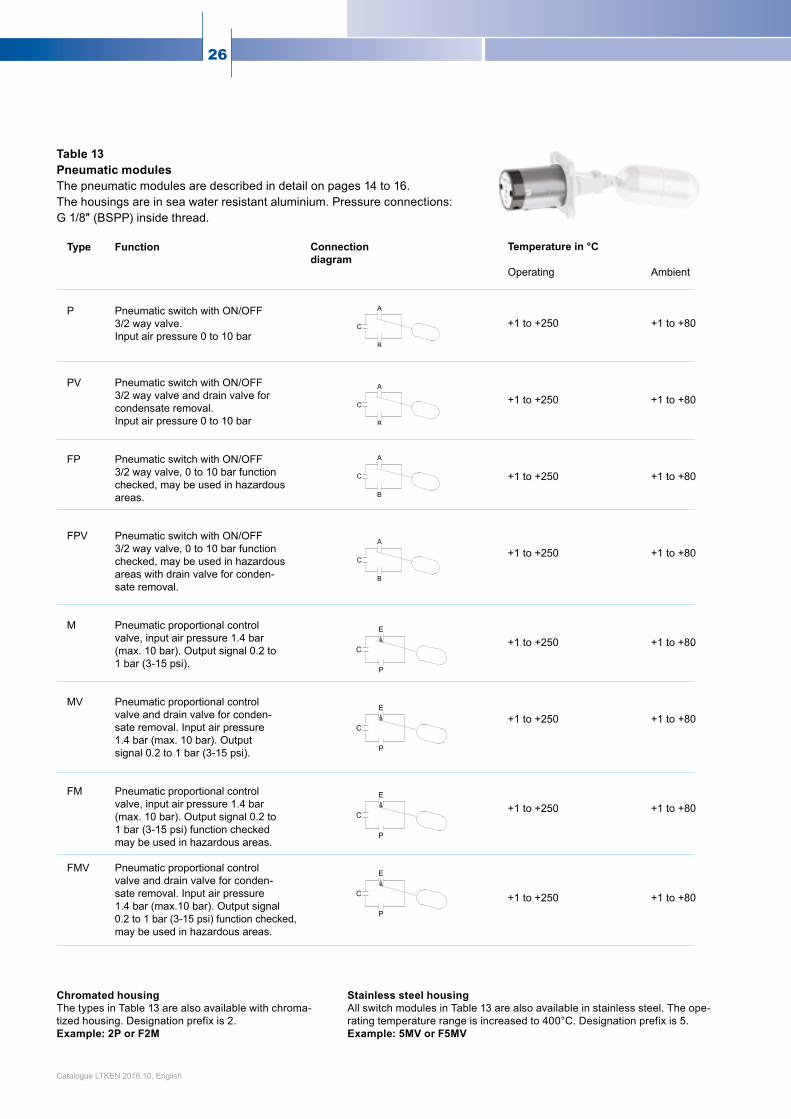
Table 13Pneumatic modulesThe pneumatic modules are described in detail on pages 14 to 16. The housings are in sea water resistant aluminium. Pressure connections: G1/8″(BSPP)insidethread.
Type Function P Pneumatic switch with ON/OFF 3/2 way valve. Input air pressure 0 to 10 bar PV Pneumatic switch with ON/OFF 3/2 way valve and drain valve for condensate removal. Input air pressure 0 to 10 bar FP Pneumatic switch with ON/OFF 3/2 way valve, 0 to 10 bar function checked, may be used in hazardous areas. FPV Pneumatic switch with ON/OFF 3/2 way valve, 0 to 10 bar function checked, may be used in hazardous areas with drain valve for conden- sate removal. M Pneumatic proportional control valve, input air pressure 1.4 bar (max. 10 bar). Output signal 0.2 to 1 bar (3-15 psi). MV Pneumatic proportional control valve and drain valve for conden- sate removal. Input air pressure 1.4 bar (max. 10 bar). Output signal 0.2 to 1 bar (3-15 psi). FM Pneumatic proportional control valve, input air pressure 1.4 bar (max. 10 bar). Output signal 0.2 to 1 bar (3-15 psi) function checked may be used in hazardous areas. FMV Pneumatic proportional control valve and drain valve for conden- sate removal. Input air pressure 1.4 bar (max.10 bar). Output signal 0.2 to 1 bar (3-15 psi) function checked, may be used in hazardous areas.
Connectiondiagram
Temperature in °C Operating +1 to +250 +1 to +250 +1 to +250 +1 to +250 +1 to +250 +1 to +250 +1 to +250 +1 to +250
Ambient +1 to +80 +1 to +80 +1 to +80 +1 to +80 +1 to +80 +1 to +80 +1 to +80 +1 to +80
Chromated housing The types in Table 13 are also available with chroma-tized housing. Designation prefix is 2. Example: 2P or F2M
Stainless steel housing All switch modules in Table 13 are also available in stainless steel. The ope-rating temperature range is increased to 400°C. Designation prefix is 5. Example: 5MV or F5MV
Catalogue LTKEN 2016.10, English

27www.trimodbesta.com
Pressureequipmentdirective(PED)97/23/EC: Forswitchesaccordingtodirective97/23/ECaddthe letter «P» after flange name, e.g. A 01P 041
Theflangemoduleisselectedaccordingtotherequiredflangestandard,nominalpressurerating(PN),nominalsize(DN),typeofgasket,propertiesofthemediumandflangematerial.Abasicdistinctionismadebetweenflangemod-ules for the Standard Range, the Industrial Range and the PlasticRange.Theflangemodulesmaybeinstalledeitherhorizontally or vertically.
Flange modules
Type Standard flange 01 Square flange incl. gasket Material 1.4408 Nominal pressure PN 25, max. 25 bar up to 300°C Flange facing Raised face Temperature range -196 to 300°C Counterflange see page 38 011 Round flange incl. gasket Material 1.4571 Nominal pressure PN 25, max. 25 bar up to 300°C
max. 23 bar at 400°C Flange facing Raised face Temperature range -196 to 400°C Counterflange see page 38
Type Special flanges 03 Round flange incl. gasket Material 1.4571 Nominal pressure PN 25, max. 25 bar up to 300°C
max. 23 bar at 400°C Flange facing Raised face Temperature range -196 to 400°C 04 Round flange incl. gasket Material 1.4571 Nominal pressure PN 25, max. 25 bar up to 300°C
max. 23 bar at 400°C Flange facing Raised face Temperature range -196 to 400°C 06 Round flange incl. gasket Material 1.4571 Nominal pressure PN 25, max. 25 bar up to 300°C
max. 23 bar at 400°C Flange facing Raised face Temperature range -196 to 400°C
Table 14Flange modules for the Standard Range
Catalogue LTKEN 2016.10, English

28
L
Flange modules for the Industrial Range acc. to EN/DIN, ANSI, BS, JIS Foreconomicreasons,theflangemodulesoftheIndustrialRangearemanu-facturedintwodifferentexecutions.Thefixedflangeforthemostdemandingrequirements in respect of temperature range and corrosion resistance and the compositeflangeforbesteconomy.
Other bracket length than 68 mm, and/or fixed flange execution and/or other
materials, and/or PED conformity
Flange facing
Nominal pressure (PN)
Nominal bore (DN)
Standard (For EN/DIN without code)
Important note: Ensure that nozzle length L and diameter provide sufficient clearance for float movement. (See table 26, page 35.)
Key to type numbers
Switch module Page 21
Float module Page 32
Flange module Table 14 - 16
(Table15)
Fixed flange Temperature range Material Options Composite flange Temperature range Materials Sealing unit Slip-on Flange Options Sealing unit Slip-on Flange
-196 to +400°C 1.4571 1.4435 (316L), Hastelloy C Ifafixedflangeisrequiredpleaseconsultusto select the correct type number. Type designation see table 15. -10 to +400°C (EN/DIN) -29 to +400°C (ANSI) 1.4571(316Ti) Carbon steel P265GH zinc galvanized and passivated 1.4435 (316L), Hastelloy C Type designation see table 15. 13 CrMo 4-5 (high temp. steel) A 350-LF2 (low temp. steel)
Fixedflange:1.4571
Sealingunit:1.4571
Slip-on Flange: Carbon steel P265GH zinc galvanised and passivated
Catalogue LTKEN 2016.10, English

29www.trimodbesta.com
Table 15Type of flange module according to EN 1092-1 (DIN 2501)
Suffixforflangefacings:Raised face type B1 (type C - DIN 2526) C PN 16 to 40Raised face type B2 (type E - DIN 2526) E PN 63 to 320Male type E (type V13 - DIN 2513) V PN 16 to 100Groove type D (type N - DIN 2512) N PN 16 to 160Groove for DIN 2696 L PN 63 to 320metaljointExample: DIN-flangemodule,DN65,PN40,male:22V
Suffixforflangefacings:Large raised face: RMale: MTongue: TGroove: GExample: JIS-Flange module DN 80A, PN 30K, groove: 332G
Suffixforflangefacings:Raised face RF R Small male SMF M Small tongue STF T Small groove SGF G Ringjoint RTJ JExample: ANSI-FlangemoduleDN4″,PNcl.900,smallgroove:145G
Suffixforflangefacing:Raised face RExample: BS-Flangemodule4″,TableK:243 R
Type of flange module according to JIS B 2220
Type of flange module according to ANSI B16.5
Type of flange module according to BS 10
PN 16 PN 40 PN 63 PN 100 PN 160 PN 250 PN 320DN 65 21. 22. 23. 24. 25. - 27.DN 80 31. 32. 33. 34. 35. 36. 37.DN 100 41. 42. 43. 44. 45. 46. 47.DN 125 51. 52. 53. 54. - - -DN 150 61. 62. 63. 64. - - -
cl. 150 cl. 300 cl. 400 cl. 600 cl. 900 cl. 1500 cl. 2500DN 3″ 131. 132. - 134. 135. 136. 137.DN 4″ 141. 142. 143. 144. 145. 146. 147JDN 5″ 151. 152. 153. 154. - - -DN 6″ 161. 162. 163. 164. - - -
Tbl. E Tbl. F Tbl. H Tbl. K Tbl. R Tbl. S Tbl. TDN 3″ 230R 231R 232R 233R 234R 235R 236RDN 4″ 240R 241R 242R 243R 244R 245R 246RDN 5″ 250R 251R 252R 253R 254R - -DN 6″ 260R 261R 262R 263R 264R - -
5K 10K 16K 20K 30K 40K 63KDN 65 329. 320. 328. 321. 322. 323. 324.DN 80 339. 330. 338. 331. 332. 333. 334.DN 100 - 340. - 341. 352. 343. 344.DN 125 - 350. - 351. 352. 353. 354.
Catalogue LTKEN 2016.10, English

30
cl.600
PN 100
cl.400
PN 63
PN 40
0 50
10
20
30
40
50
60
70
80
90
100
100 150 200 250 300 350
cl.300
cl.150
400°C
PN 25
PN 16
-200 -150
1
2
3
4
5
6
7
8
9
10
bar
bar
-100 -50 0 50 100 150
PTFE
200°C
PVC
PP
PVDF*
Pressure/Temperature Diagram Plastics
Pressure/Temperature Diagram acc. to EN 1092-1 and ANSI B16.5
Only carbon steel is shown up to PN 100 / class 600. For higher nominal pressure ratings up to PN 320 / cl.2500 and for other materials, such as heat resistant or stainless steels, please consult the corresponding standards.
EN 1092-1 (P265GH, etc.)ANSI B 16.5 (Mat. Gr. 1.1)
Catalogue LTKEN 2016.10, English
31www.trimodbesta.com
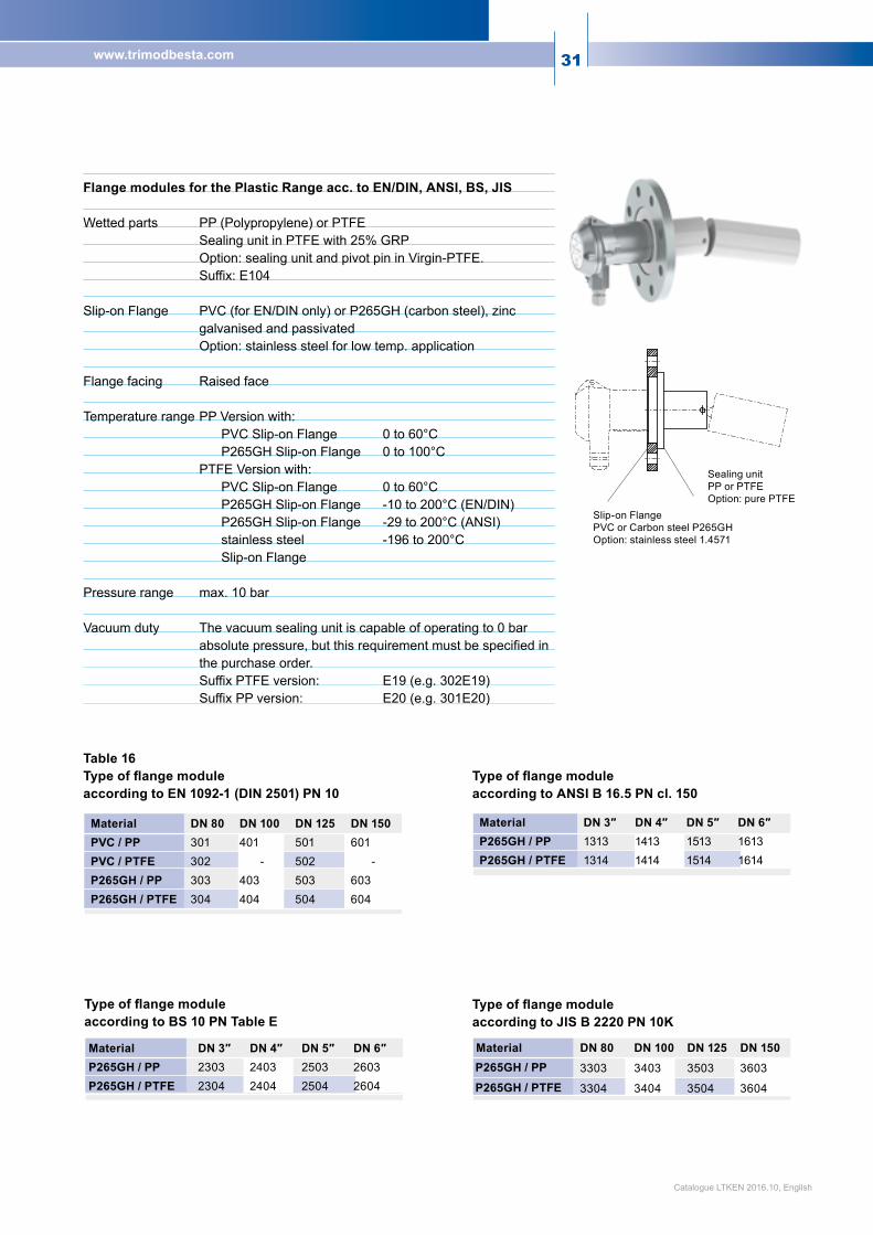
Flange modules for the Plastic Range acc. to EN/DIN, ANSI, BS, JIS Wetted parts PP (Polypropylene) or PTFE Sealing unit in PTFE with 25% GRP Option: sealing unit and pivot pin in Virgin-PTFE. Suffix: E104 Slip-on Flange PVC (for EN/DIN only) or P265GH (carbon steel), zinc galvanised and passivated Option: stainless steel for low temp. application Flange facing Raised face Temperature range PP Version with: PVC Slip-on Flange 0 to 60°C P265GH Slip-on Flange 0 to 100°C PTFE Version with: PVC Slip-on Flange 0 to 60°C P265GH Slip-on Flange -10 to 200°C (EN/DIN) P265GH Slip-on Flange -29 to 200°C (ANSI) stainless steel -196 to 200°C Slip-on Flange Pressure range max. 10 bar Vacuum duty The vacuum sealing unit is capable of operating to 0 bar
absolute pressure, but this requirement must be specified in the purchase order. Suffix PTFE version: E19 (e.g. 302E19) Suffix PP version: E20 (e.g. 301E20)
Slip-on FlangePVC or Carbon steel P265GHOption:stainlesssteel1.4571
Sealing unitPP or PTFEOption: pure PTFE
Table 16Type of flange module according to EN 1092-1 (DIN 2501) PN 10
Type of flange module according to ANSI B 16.5 PN cl. 150
Type of flange module according to JIS B 2220 PN 10K
Type of flange module according to BS 10 PN Table E
Material DN 80 DN 100 DN 125 DN 150PVC / PP 301 401 501 601PVC / PTFE 302 - 502 -P265GH / PP 303 403 503 603P265GH / PTFE 304 404 504 604
Material DN 3″ DN 4″ DN 5″ DN 6″P265GH / PP 2303 2403 2503 2603P265GH / PTFE 2304 2404 2504 2604
Material DN 80 DN 100 DN 125 DN 150P265GH / PP 3303 3403 3503 3603
P265GH / PTFE 3304 3404 3504 3604
Material DN 3″ DN 4″ DN 5″ DN 6″P265GH / PP 1313 1413 1513 1613P265GH / PTFE 1314 1414 1514 1614
Catalogue LTKEN 2016.10, English
32
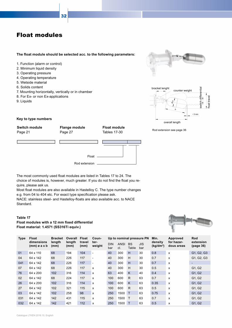
The float module should be selected acc. to the following parameters: 1. Function (alarm or control) 2. Minimum liquid density 3. Operating pressure 4. Operating temperature 5. Wetside material 6. Solids content 7.Mountinghorizontally,verticallyorinchamber8. For Ex- or non Ex-applications9. Liquids
ThemostcommonlyusedfloatmodulesarelistedinTables17to24.Thechoiceofmodulesis,however,muchgreater.Ifyoudonotfindthefloatyoure-quire, please ask us. MostfloatmodulesarealsoavailableinHastelloyC.Thetypenumberchangese.g.from04to404etc.Forexacttypespecificationpleaseask. NACE:stainlesssteel-andHastelloy-floatsarealsoavailableacc.toNACEStandard.
Table 17 Float modules with a 12 mm fixed differential Float material: 1.4571 (SS316Ti equiv.)
Float
Rod extension
Rod extension see page 36
Float modules
Key to type numbers
Switch module Page 21
Float module Tables17-30
Flange module Page27
overall length
bracket lenghtcounter weight
switc
h di
ffere
ntia
l
float
trav
el
Type Floatdimensions(mm) ø a x b
Bracketlength(mm)
Overalllength(mm)
Floattravel(mm)
Coun-ter-weight
Up to nominal pressure PN Min.density(kg/dm³)
Approvedfor hazar-dous areas
Rodextension(page 36)DIN
barANSIcl.
BSTable
JIS bar
01 64 x 110 68 194 104 - 40 300 H 30 0.8 x G1, G2, G304 64 x 142 68 226 117 - 40 300 H 30 0.7 x G1, G2, G3041 64 x 142 68 226 117 - 40 300 H 30 0.7 x -07 64 x 142 68 226 117 x 40 300 H 30 0.5 x G1, G276 64 x 200 102 316 114 x 63 400 K 40 0.4 x G1, G202 64 x 142 68 224 117 x 100 600 R 63 0.7 x G1, G226 64 x 200 102 316 114 x 100 600 K 63 0.35 x G1, G227 64 x 142 102 321 115 x 100 600 R 63 0.5 x G1, G203 64 x 142 102 258 98 x 250 1500 T 63 0.75 x G1, G2031 64 x 142 142 431 115 x 250 1500 T 63 0.7 x G1, G2032 64 x 142 142 421 112 x 250 1500 T 63 0.5 x G1, G2
Catalogue LTKEN 2016.10, English
33www.trimodbesta.com
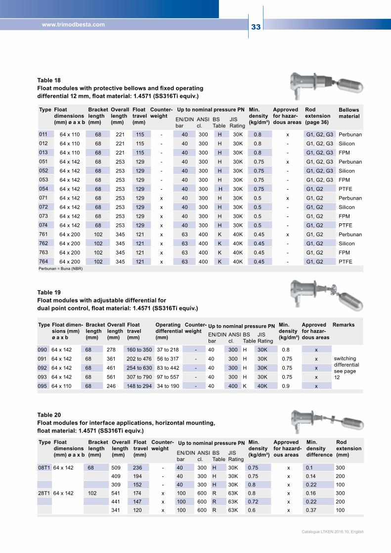
Table 18 Float modules with protective bellows and fixed operating differential 12 mm, float material: 1.4571 (SS316Ti equiv.)
Table 20 Float modules for interface applications, horizontal mounting, float material: 1.4571 (SS316Ti equiv.)
Table 19 Float modules with adjustable differential for dual point control, float material: 1.4571 (SS316Ti equiv.)
Type Floatdimensions(mm) ø a x b
Bracketlength(mm)
Overalllength(mm)
Floattravel(mm)
Counter-weight
Up to nominal pressure PN Min.density(kg/dm³)
Approved for hazar-dous areas
Rodextension(page 36)
BellowsmaterialEN/DIN
barANSIcl.
BSTable
JIS Rating
011 64 x 110 68 221 115 - 40 300 H 30K 0.8 x G1, G2, G3 Perbunan
012 64 x 110 68 221 115 - 40 300 H 30K 0.8 - G1, G2, G3 Silicon
013 64 x 110 68 221 115 - 40 300 H 30K 0.8 - G1, G2, G3 FPM
051 64 x 142 68 253 129 - 40 300 H 30K 0.75 x G1, G2, G3 Perbunan
052 64 x 142 68 253 129 - 40 300 H 30K 0.75 - G1, G2, G3 Silicon
053 64 x 142 68 253 129 - 40 300 H 30K 0.75 - G1, G2, G3 FPM
054 64 x 142 68 253 129 - 40 300 H 30K 0.75 - G1, G2 PTFE
071 64 x 142 68 253 129 x 40 300 H 30K 0.5 x G1, G2 Perbunan
072 64 x 142 68 253 129 x 40 300 H 30K 0.5 - G1, G2 Silicon
073 64 x 142 68 253 129 x 40 300 H 30K 0.5 - G1, G2 FPM
074 64 x 142 68 253 129 x 40 300 H 30K 0.5 - G1, G2 PTFE
761 64 x 200 102 345 121 x 63 400 K 40K 0.45 x G1, G2 Perbunan
762 64 x 200 102 345 121 x 63 400 K 40K 0.45 - G1, G2 Silicon
763 64 x 200 102 345 121 x 63 400 K 40K 0.45 - G1, G2 FPM
764 64 x 200 102 345 121 x 63 400 K 40K 0.45 - G1, G2 PTFEPerbunan = Buna (NBR)
Type Float dimen-sions (mm) ø a x b
Bracketlength(mm)
Overalllength(mm)
Float travel(mm)
Operating differential (mm)
Counter-weight
Up to nominal pressure PN Min.density(kg/dm³)
Approved for hazar-dous areas
Remarks
EN/DINbar
ANSIcl.
BSTable
JIS Rating
090 64 x 142 68 278 160 to 350 37to218 - 40 300 H 30K 0.8 xswitching differential see page 12
091 64 x 142 68 361 202to476 56to317 - 40 300 H 30K 0.75 x
092 64 x 142 68 461 254 to 630 83 to 442 - 40 300 H 30K 0.75 x
093 64 x 142 68 561 307to790 97to557 - 40 300 H 30K 0.75 x
095 64 x 110 68 246 148 to 294 34 to 190 - 40 400 K 40K 0.9 x
Type Floatdimensions(mm) ø a x b
Bracket length(mm)
Overalllength(mm)
Floattravel(mm)
Counter-weight
Up to nominal pressure PN Min.density(kg/dm³)
Approvedfor hazard-ous areas
Min.densitydifference
Rodextension(mm)EN/DIN
barANSIcl.
BSTable
JIS Rating
08T1 64 x 142 68 509 236 - 40 300 H 30K 0.75 x 0.1 300409 194 - 40 300 H 30K 0.75 x 0.14 200309 152 - 40 300 H 30K 0.8 x 0.22 100
28T1 64 x 142 102 541 174 x 100 600 R 63K 0.8 x 0.16 300441 147 x 100 600 R 63K 0.72 x 0.22 200341 120 x 100 600 R 63K 0.6 x 0.37 100
Catalogue LTKEN 2016.10, English
34
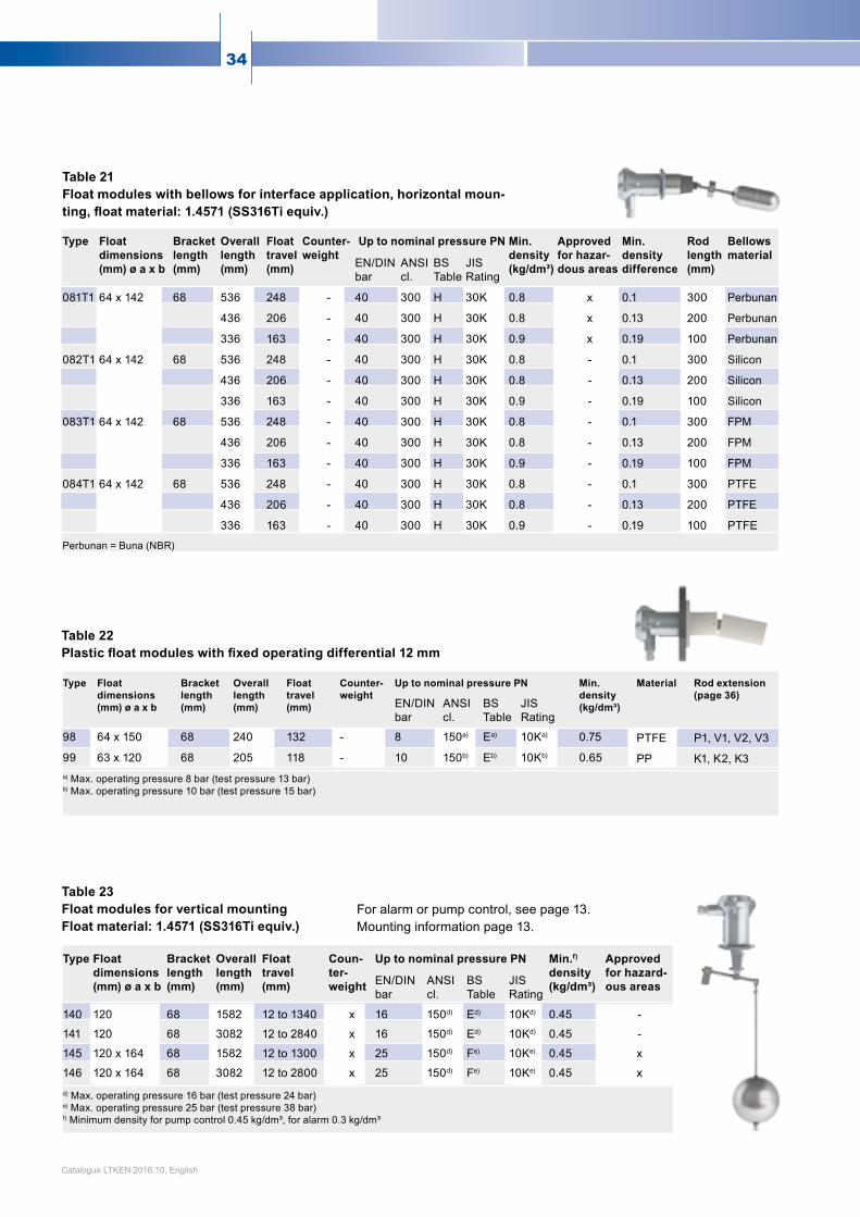
Table 21Float modules with bellows for interface application, horizontal moun-ting, float material: 1.4571 (SS316Ti equiv.)
Table 22Plastic float modules with fixed operating differential 12 mm
For alarm or pump control, see page 13. Mounting information page 13.
Table 23Float modules for vertical mountingFloat material: 1.4571 (SS316Ti equiv.)
Type Floatdimensions(mm) ø a x b
Bracketlength(mm)
Overalllength(mm)
Floattravel(mm)
Counter-weight
Up to nominal pressure PN Min.density(kg/dm³)
Approvedfor hazar-dous areas
Min.densitydifference
Rodlength(mm)
Bellowsmaterial
EN/DINbar
ANSIcl.
BSTable
JIS Rating
081T1 64 x 142 68 536 248 - 40 300 H 30K 0.8 x 0.1 300 Perbunan
436 206 - 40 300 H 30K 0.8 x 0.13 200 Perbunan
336 163 - 40 300 H 30K 0.9 x 0.19 100 Perbunan
082T1 64 x 142 68 536 248 - 40 300 H 30K 0.8 - 0.1 300 Silicon
436 206 - 40 300 H 30K 0.8 - 0.13 200 Silicon
336 163 - 40 300 H 30K 0.9 - 0.19 100 Silicon
083T1 64 x 142 68 536 248 - 40 300 H 30K 0.8 - 0.1 300 FPM
436 206 - 40 300 H 30K 0.8 - 0.13 200 FPM
336 163 - 40 300 H 30K 0.9 - 0.19 100 FPM
084T1 64 x 142 68 536 248 - 40 300 H 30K 0.8 - 0.1 300 PTFE
436 206 - 40 300 H 30K 0.8 - 0.13 200 PTFE
336 163 - 40 300 H 30K 0.9 - 0.19 100 PTFE
Perbunan = Buna (NBR)
Type Floatdimensions(mm) ø a x b
Bracketlength(mm)
Overalllength(mm)
Floattravel(mm)
Counter-weight
Up to nominal pressure PN Min.density(kg/dm³)
Material Rod extension(page 36)
EN/DINbar
ANSIcl.
BSTable
JIS Rating
98 64 x 150 68 240 132 - 8 150a) Ea) 10Ka) 0.75 PTFE P1, V1, V2, V3
99 63 x 120 68 205 118 - 10 150b) Eb) 10Kb) 0.65 PP K1, K2, K3a) Max. operating pressure 8 bar (test pressure 13 bar)b) Max. operating pressure 10 bar (test pressure 15 bar)
Type Floatdimensions(mm) ø a x b
Bracketlength(mm)
Overalllength(mm)
Floattravel(mm)
Coun-ter-weight
Up to nominal pressure PN Min.f)
density (kg/dm³)
Approvedfor hazard-ous areasEN/DIN
barANSIcl.
BSTable
JIS Rating
140 120 68 1582 12 to 1340 x 16 150d) Ed) 10Kd) 0.45 -
141 120 68 3082 12 to 2840 x 16 150d) Ed) 10Kd) 0.45 -
145 120 x 164 68 1582 12 to 1300 x 25 150d) Fe) 10Ke) 0.45 x
146 120 x 164 68 3082 12 to 2800 x 25 150d) Fe) 10Ke) 0.45 xd) Max. operating pressure 16 bar (test pressure 24 bar)e) Max. operating pressure 25 bar (test pressure 38 bar)f) Minimum density for pump control 0.45 kg/dm³, for alarm 0.3 kg/dm³
Catalogue LTKEN 2016.10, English
35www.trimodbesta.com
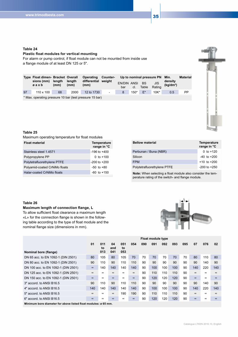
LTable 26 Maximum length of connection flange, L To allow sufficient float clearance a maximum length «L» for the connection flange is shown in the follow-ing table according to the type of float module and the nominal flange size (dimensions in mm).
Table 25Maximum operating temperature for float modules
Table 24 Plastic float modules for vertical mounting For alarm or pump control, if float module can not be mounted from inside use aflangemoduleofatleastDN125or5″.
Type Float dimen-sions (mm)ø a x b
Bracket length (mm)
Overalllength(mm)
Operatingdifferential(mm)
Counter-weight
Up to nominal pressure PN Min.density(kg/dm³)
Material
EN/DINbar
ANSIcl.
BSTable
JIS Rating
97 110 x 100 68 2000 12to1730 - 8 150* E* 10K* 0.5 PP* Max. operating pressure 10 bar (test pressure 15 bar)
Float material Temperaturerange in °C
Stainlesssteel1.4571 -196 to +400Polypropylene PP 0 to +100PolytetrafluorethylenePTFE -200 to +200Polyamid-coatedCrNiMofloats -50 to +80Halar-coatedCrNiMofloats -60 to +150
Bellow material Temperaturerange in °C
Perbunan / Buna (NBR) 0 to +120Silicon -40 to +200FPM +10 to +200PolytetrafluorethylenePTFE -200 to +250
Note: Whenselectingafloatmodulealsoconsiderthetem-peratureratingoftheswitch-andflangemodule.
Nominal bore (flange)
Float module type01 011
to 013
04 and 041
051 to
053
054 090 091 092 093 095 07 076 02
DN 65 acc. to EN 1092-1 (DIN 2501) 80 105 80 105 70 70 70 70 70 70 80 110 80DN 80 acc. to EN 1092-1 (DIN 2501) 90 110 90 110 110 90 90 90 90 90 90 140 90DN 100 acc. to EN 1092-1 (DIN 2501) 140 140 140 140 90 100 100 100 90 140 220 140DN 125 acc. to EN 1092-1 (DIN 2501) 90 110 110 110 90 DN 150 acc. to EN 1092-1 (DIN 2501) 90 120 120 120 90 3″accord.toANSIB16.5 90 110 90 110 110 90 90 90 90 90 90 140 904″accord.toANSIB16.5 140 140 140 140 140 90 100 100 100 90 140 220 1405″accord.toANSIB16.5 190 190 90 110 110 110 90 6″accord.toANSIB16.5 90 120 120 120 90 Minimum bore diameter for above listed float modules: ø 65 mm.
Catalogue LTKEN 2016.10, English

36
Rod extensions Wherethefloatpivotneedstobeprotectedfromcontaminatedmediaortoprovideanincreasedswitchingdifferentialthefloatcanbeequippedwitharodextension.
Table 27Type of rod extensions (Dimensions in mm)
Table 30Minimum density for float module 04G3 (kg/dm³)
Sincerodextensionsadd-onweighttothefloat,theminimumvalueforthedensitywillchangeaccordingtothefollowingtables.Tables28to30listtheminimumdensitiesforfloatmodule04withextensionsG1,G2andG3only.Forotherfloatmodules and rod extensions with other dimensions or materials, please consult the factory.
Table 28 Minimum density for float module 04G1
Table 29 Minimum density for float module 04G2 (kg/dm³)
Rod length A (mm) 100 200 300 400 500 600 700 800 900 1000
Min. density (kg/dm ) 0.66 0.66 0.67 0.69 0.71 0.74 0.76 0.79 0.81 0.84
A (mm) 100 200 300 400 500 600 700 800
B (mm)100 0.69 0.68 0.70 0.71 0.72 0.74 0.75 -200 0.67 0.67 0.68 0.69 0.70 0.71 0.72 0.73300 0.68 0.69 0.69 0.70 0.71 0.71 0.72400 0.70 0.70 0.71 0.71 0.72 0.73500 0.72 0.73 0.73 0.73 0.74600 0.74 0.75 0.75 0.75700 0.77 0.77 0.77800 0.79 0.80900 0.82
A (mm) 50-500 600 700 800
B (mm)50 0.71 - - -
100 0.69 - - -200 0.68 0.68 0.68 0.68300 0.69 0.69 0.69400 0.71 0.71500 0.73600 0.75700 0.77800 0.80900 0.82950 0.83
Catalogue LTKEN 2016.10, English
Rod extensionmaterial
To matchfloat modules
Stainless steel (CrNiMo)
Stainless steel (CrNiMo)
Type: G1 A max: 1000 Type: G2 A+B max: 1000 A/B: ≤4 A min: 100 B min: 100
*Type: G3 A+B max: 1000 A/B: ≤4 A min: 50 B min: 60
PP PP Type: K1 A min: 100 A max: 1000
Type: K2 A+B max: 1000 A min: 100 B min: 200
Type: K3 A+B max: 1000 A/B: ≤3 A min: 100 B min: 100
PVDF PTFE Type: V1 A min: 100 A max: 1000
Type: V2 A+B max: 1000 A min: 100 B min: 200
Type: V3 A+B max: 1000 A/B: ≤4 A min: 100 B min: 100
PTFE PTFE Type: P1 A min: 100 A max: 300
--
--
* Rod extension type G3 is available with 90° or 135° angle.

37www.trimodbesta.com
IfyouhaveaspecialrequirementforaTrimodBestalevelswitch,pleasesendusacompletedcopyofthisspecificationsheet together with any relevant drawing etc. and we will respond with a quotation.
Specification sheet
Liquid _________________________________ Operating/ambient temperature ___________°C / _________ °C
Density___________________________ kg/dm³ Tank material ______________________________________
Operating pressure _____________________ bar Tank measurement __________________________________
Application Type of mounting
High alarm Interface application Side mounted
Low alarm Regulating (pneumatic) Top mounted
2-point control In float chamber (by-pass)
Switch module type Electric Electronic Pneumatic
Contact type SPDT 2 x SPDT I IE9 On/Off
Silver Gold plated IN INE9 proportional
Safety Integrity Level (SIL) SIL 1 SIL 2
Approval classification Ex ed IIC T6…T5 (Hermetically sealed)
Ex ia IIC T6…T2 (Intrinsically safe circuits)
Ex de IIC T6 (Flameproof)
Cable gland M20 x 1.5 3/4″NPT
Enclosure material Die cast aluminium Die cast aluminium, chromated Stainless steel
Enclosure rating IP65 IP66/IP67 IP68, cable length _________________________________
Remarks __________________________________________________________________________________
Flange module type
Flange type Square flange 92 x 92 Fixed Flange Slip-on Flange
DN/PN ANSI EN/DIN DN _______ PN _______ Seal type __________
Wetted parts material CrNiMo Hastelloy C PP PTFE Other ___________
Slip-on Flange material Carbon steel P265GH zinc galvanized and passivated Other ___________
Remarks __________________________________________________________________________________
Float module type
Float material CrNiMo Hastelloy C PP PTFE
Differential Fixed 12 mm Variable between ____________________________________________________
Bellows Perbunan (NBR) Silicon FPM PTFE
Remarks __________________________________________________________________________________
Options
Float rod extension G1 G2 G3 Dim. A mm Dim. B mm
Counterflanges Carbon steel CrNiMo
Test actuators CrNiMo / FPM CrNiMo / EPDM
Test certificates T-100 (2.2) T-101 (3.1) T-110 (test certi-ficate)
Tag No. ______________________________ ________________________________________________Catalogue LTKEN 2016.10, English
38
Accessories
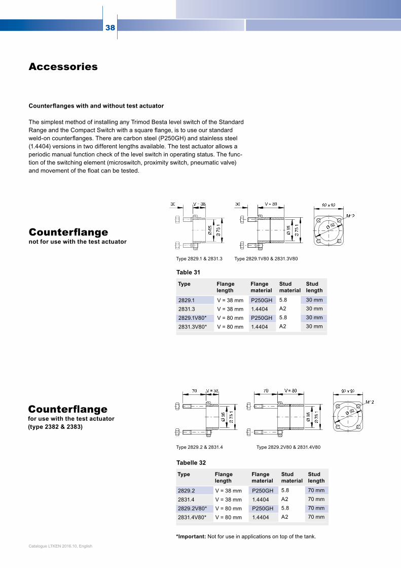
Counterflanges with and without test actuator
The simplest method of installing any Trimod Besta level switch of the Standard Range and the Compact Switch with a squareflange,istouseourstandardweld-oncounterflanges.Therearecarbon steel (P250GH) and stainless steel (1.4404) versions in two different lengths available. The test actuator allows a periodic manual function check of the level switch in operating status. The func-tion of the switching element (microswitch, proximity switch, pneumatic valve) andmovementofthefloatcanbetested.
*Important: Not for use in applications on top of the tank.
Table 31
Tabelle 32
Type Flange length
Flange material
Stud material
Stud length
2829.1 V = 38 mm P250GH 5.8 30 mm
2831.3 V = 38 mm 1.4404 A2 30 mm
2829.1V80* V = 80 mm P250GH 5.8 30 mm
2831.3V80* V = 80 mm 1.4404 A2 30 mm
Type Flange length
Flange material
Stud material
Stud length
2829.2 V = 38 mm P250GH 5.8 70mm
2831.4 V = 38 mm 1.4404 A2 70mm
2829.2V80* V = 80 mm P250GH 5.8 70mm
2831.4V80* V = 80 mm 1.4404 A2 70mm
Counterflangenot for use with the test actuator
Counterflangefor use with the test actuator (type 2382 & 2383)
Type 2829.1 & 2831.3 Type 2829.1V80 & 2831.3V80
Type 2829.2 & 2831.4 Type 2829.2V80 & 2831.4V80
Catalogue LTKEN 2016.10, English
39www.trimodbesta.com
Ø
76.
1
150
40 2
O-Ring
FlanschdichtungBlue-Gard BG3000
150
L1
= 65
ø 76
.2 ø 65
V=50 30
M12
14.5
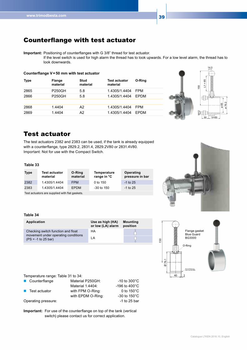
Table 34
Table 33
Application Use as high (HA)or low (LA) alarm
Mounting position
Checking switch function and float movement under operating conditions (PS = -1 to 25 bar)
HA
LA
Test actuator
Type Test actuator material
O-Ring material
Temperature range in °C
Operating pressure in bar
2382 1.4305/1.4404 FPM 0 to 150 -1 to 252383 1.4305/1.4404 EPDM -30 to 150 -1 to 25Test actuators are supplied with flat gaskets.
Flange gasket Blue Guard BG3000
The test actuators 2382 and 2383 can be used, if the tank is already equipped withacounterflange,type2829.2,2831.4,2829.2V80or2831.4V80.Important: Not for use with the Compact Switch.
Temperature range: Table 31 to 34: Counterflange MaterialP250GH: -10to300°C Material 1.4404: -196 to 400°C Test actuator with FPM O-Ring: 0 to 150°C with EPDM O-Ring: -30 to 150°COperating pressure: -1 to 25 bar
Important:Foruseofthecounterflangeontopofthetank(verticalswitch) please contact us for correct application.
Catalogue LTKEN 2016.10, English
Type Flange material
Stud material
Test actuator material
O-Ring
2865 P250GH 5.8 1.4305/1.4404 FPM2866 P250GH 5.8 1.4305/1.4404 EPDM
2868 1.4404 A2 1.4305/1.4404 FPM2869 1.4404 A2 1.4305/1.4404 EPDM
Counterflange with test actuator
Important: PositioningofcounterflangeswithG3/8”threadfortestactuator. If the level switch is used for high alarm the thread has to look upwards. For a low level alarm, the thread has to look downwards.
Counterflange V = 50 mm with test actuator
40
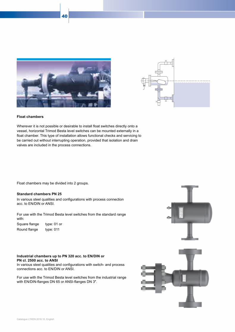
Float chambers Wherever it is not possible or desirable to install float switches directly onto a vessel, horizontal Trimod Besta level switches can be mounted externally in a float chamber. This type of installation allows functional checks and servicing to be carried out without interrupting operation, provided that isolation and drain valves are included in the process connections.
Float chambers may be divided into 2 groups.
Standard chambers PN 25In various steel qualities and configurations with process connection acc. to EN/DIN or ANSI.
For use with the Trimod Besta level switches from the standard range with:Square flange type: 01 orRound flange type: 011
Industrial chambers up to PN 320 acc. to EN/DIN or PN cl. 2500 acc. to ANSIIn various steel qualities and configurations with switch- and process connections acc. to EN/DIN or ANSI.
For use with the Trimod Besta level switches from the industrial range withEN/DIN-flangesDN65orANSI-flangesDN3″.
Catalogue LTKEN 2016.10, English

41www.trimodbesta.com
C D
E F
G H
B
C D
E F
G H
A B
A
Types AccordingtofiguresAtoHProcess connections DN 25, 50 in accordance with EN/DIN DN1″,2″inaccordancewithANSIMaterial Carbon steel High temperature steel CrNi steel CrNiMo steelFlange facing of in accordance with EN 1092-1 (DIN 2526) and ANSI B16.5process connections Options Special dimensions Vent and drain connection Long studs for mounting a test actuator Float chambers for low temperature applications Float chambers with max. hardness of HRC 22 in accordance with NACE
Table 37 Standard chambers PN 25
Table 38 Industrial chambers PN 40 to 100 and ANSI PN cl. 150 to 600
Types AccordingtofiguresAtoHProcess connections DN 25, 50 in accordance with EN/DIN DN1″,2″inaccordancewithANSIMaterial Carbon steel High temperature steel CrNi steel CrNiMo steelFlange facing of in accordance with EN 1092-1 (DIN 2526) and ANSI B16.5process connections Options Special dimensions Vent and drain connection Chambers up to PN 320 in accordance with EN/DIN, PN cl.
2500 with ANSI Float chambers for low temperature applications Float chambers with max. hardness of HRC 22 in accordance with NACE
Catalogue LTKEN 2016.10, English

42
For float chambers in Tables 37 and 38, the following options, tests and documentation are available: Test report in accordance with EN 10204-2.2
InspectioncertificateinaccordancewithEN10204-3.1 Non destructive testing such as ultrasonic, X-ray, dye penetrant or magnetic particle examination Material testing including charpy, tensile and hardness Design-examination for PED in accordance with 2014/68/EU Coatings
Catalogue LTKEN 2016.10, English

43www.trimodbesta.com
Flameproof Trimod Besta Level Switches Flameproof Trimod Besta level switches are designed in accordance with ATEX, IECEx and EAC Ex standards and are tested and approved.
Protection classifications: Ex de IIC T6 Ga/Gb for switch modules XA..8 etc. EPS 09 ATEX 1238 XEx ia d IIC T6 Ga/Gb for switch modules XB..8, XI..8, XIE9..8 etc. EPS 09 ATEX 1238 XExdeIICT6Ga/Gb forswitchmodulesXA...5etc. IECExEPS15.0037XExiadIICT6Ga/Gb forswitchmodulesXB...5,XI...5,XIE9...5etc.IECExEPS15.0037X Ga/Gb Ex de IIC T6 X for switch modules XA..1 etc. TCRUC-CH.ГБ05.B.00783Ga/Gb Ex ia d IIC T6 X for switch modules XB..1, XI..1, XIE9..1 etc. TCRUC-CH.ГБ05.B.00783For type designations or details see page 25. Hermetically sealed Trimod Besta Level Switches These switches are available in three versions.
Protection classifications:Ex ed IIC T5...T6 Ga/Gb for switch modules Z..8 etc. EPS 12 ATEX 1430 XEx ed IIC T5...T6 Ga/Gb for switch modules Z..5 etc. IECEx EPS 15.0038 XGa/Gb Ex ed IIC T6...T5 X for switch modules Z..1 etc. TCRUC-CH.ГБ05.B.00783For type designations or details see page 24.
Trimod Besta Level Switches for use in intrinsically safe installations Level switches with proximity switches acc. to NAMUR (type range I.. and IE9.. etc.) or micro switches with gold plated contacts (type range B) are for connection to intrinsically safe circuits and approved, depending on national regulations, for Zone 1, floats in Zone 0. Protection classifications:Ex ia IIC T6…T2 Ga/Gb for switch modules I..8, IE9..8 etc. EPS 12 ATEX 1430 XEx ia IIC T6 Ga/Gb for switch modules B...8 etc. EPS 12 ATEX 1430 XEx ia IIC T6...T2 Ga/Gb for switch modules I...5, IE9...5 etc. IECEx EPS 15.0038 XEx ia IIC T6 Ga/Gb for switch modules B...5 etc. IECEx EPS 15.0038 XFor type designations or details see pages 21 and 23.
Pneumatic Trimod Besta Level Switches and Level Controllers Pneumatic level switches of the type ranges FP and FM are approved for installation in Zone 1, floats in Zone 0.For type designations and details see page 26. Mode of installation All Trimod Besta level switches of the Ex-proof range may be side or top mounted.
Trimod Besta Level Switchesin hazardous areas
For level monitoring in hazardous areas, the following Trimod Besta level switches are available:
Flameproof version
Hermetically sealed version
For intrinsically safe installation
Pneumatic version
Catalogue LTKEN 2016.10, English
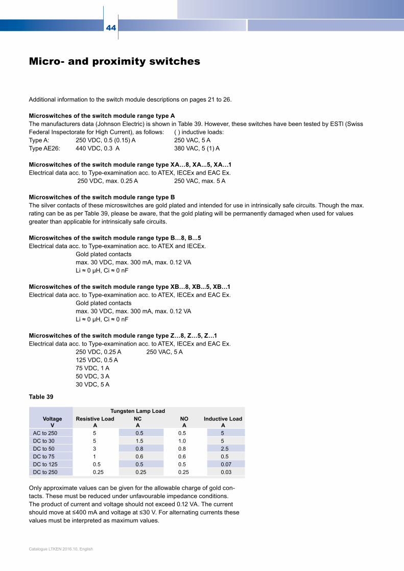
44
Additional information to the switch module descriptions on pages 21 to 26. Microswitches of the switch module range type A The manufacturers data (Johnson Electric) is shown in Table 39. However, these switches have been tested by ESTl (Swiss Federal Inspectorate for High Current), as follows: ( ) inductive loads: Type A: 250 VDC, 0.5 (0.15) A 250 VAC, 5 A Type AE26: 440 VDC, 0.3 A 380 VAC, 5 (1) A Microswitches of the switch module range type XA…8, XA...5, XA…1 Electrical data acc. to Type-examination acc. to ATEX, IECEx and EAC Ex. 250 VDC, max. 0.25 A 250 VAC, max. 5 A Microswitches of the switch module range type B The silver contacts of these microswitches are gold plated and intended for use in intrinsically safe circuits. Though the max. rating can be as per Table 39, please be aware, that the gold plating will be permanently damaged when used for values greater than applicable for intrinsically safe circuits. Microswitches of the switch module range type B…8, B...5 Electrical data acc. to Type-examination acc. to ATEX and IECEx. Gold plated contacts max. 30 VDC, max. 300 mA, max. 0.12 VA Li≈0µH,Ci≈0nF Microswitches of the switch module range type XB…8, XB...5, XB…1 Electrical data acc. to Type-examination acc. to ATEX, IECEx and EAC Ex. Gold plated contacts max. 30 VDC, max. 300 mA, max. 0.12 VA Li≈0µH,Ci≈0nF Microswitches of the switch module range type Z…8, Z…5, Z…1 Electrical data acc. to Type-examination acc. to ATEX, IECEx and EAC Ex. 250 VDC, 0.25 A 250 VAC, 5 A 125 VDC, 0.5 A 75VDC,1A 50 VDC, 3 A 30 VDC, 5 A
Table 39
Only approximate values can be given for the allowable charge of gold con-tacts. These must be reduced under unfavourable impedance conditions. The product of current and voltage should not exceed 0.12 VA. The current shouldmoveat≤400mAandvoltageat≤30V.Foralternatingcurrentsthesevalues must be interpreted as maximum values.
Micro- and proximity switches
Tungsten Lamp LoadVoltage
VResistive Load
ANCA
NOA
Inductive Load A
AC to 250 5 0.5 0.5 5DC to 30 5 1.5 1.0 5DC to 50 3 0.8 0.8 2.5DCto75 1 0.6 0.6 0.5DC to 125 0.5 0.5 0.5 0.07DC to 250 0.25 0.25 0.25 0.03
Catalogue LTKEN 2016.10, English

45www.trimodbesta.com
Electrical data of inductive proximity switches Nominal voltage UN 8.2 VDC ±5% Operating voltage UB 5 to 25 VDC Current consumption sensoruncovered ≥2.2mA sensorcovered ≤1mA Controlline:resistance≤50Ω
Inductive proximity switches acc. to NAMUR/EN 60947-5-6 The switch modules of the type ranges I and IE9 are especially suitable for ap-plications in hazardous areas*. The switching element, an inductive proximity sensor (Pepperl+Fuchs) contains only the oscillator. The signal is processed by a remote mounted relay amplifier unit as shown in the connection diagram. *(ATEX/IECEx) Connection diagram Special self checking failsafe features If the switch is connected for maximum current/voltage in the non alarm state the circuit can be monitored constantly for line and/or instrument failure to initiate operation of a safety shutdown. The sensor circuit of the switch modules IE9, INE9, and IIE9, are also self checkingandapprovedforsafetycircuits(TÜVtested).Withthesesensors,au-tomatic switching to the alarm state in the event of component failure is guaran-teed. When specifying a safety circuit, approved amplifiers and transistor relays must be incorporated. For use in hazardous areas the following data should be observed for Trimod Besta level switches with inductive proximity sensors: Type I, IN, II: Umax. 16VDC Li≤50µH Ci≤45nF Type IE9, INE9, IIE9: Umax.16VDC Li≤150µH Ci≤50nF
Output Input voltage
Proximity sensor
ActuatorControl circuit intrinsically safe
Amplifier unit
Relay
Catalogue LTKEN 2016.10, English

Bachofen AG Ackerstrasse 42 CH-8610 UsterSwitzerlandPhone +41 44 944 11 11Fax +41 44 944 12 [email protected]
HomepageFind your local sales and service partner underwww.trimodbesta.com
Quality ManagementThe Bachofen quality management system acc. to ISO 9001 was established in 1994.
Registered Trade MarksTrimod and Besta are registered trade marks of Bachofen AG, Switzerland.
Technical specifications are for information only and may change without notice.Catalogue LTKEN 2016.10, English
Side mounted switches for high or low alarm duties. With Lloyds Register Approval.
Opto-electronic level sensors for hori-zontal and vertical installation. Sensi-tivityadjustableviapotentiometer.
Limit switches with electric, electronic and pneumatic switch elements.Numerous shipbuilding and explosion proof approvals and registrations.