level tek ii model 5318b - robertshaw industrial · level tek ii, capacitance level switch 909gf295...
TRANSCRIPT
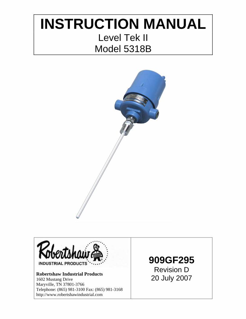
INSTRUCTION MANUAL Level Tek II
Model 5318B
Robertshaw Industrial Products 1602 Mustang Drive Maryville, TN 37801-3766 Telephone: (865) 981-3100 Fax: (865) 981-3168 http://www.robertshawindustrial.com
909GF295 Revision D
20 July 2007
MODEL 5318B INSTRUCTION MANUAL Level Tek II, Capacitance Level Switch 909GF295
Page i
RECORD OF CHANGES
Revision
Design Engineer’s Approval
Engineering Manager’s Approval
Approval Date
COS Number Brief Description
C P. Kronau B. Evans 4/20/07 96435 Corrected various typing errors.
D P. Kronau B. Evans 13AUG07 96469 Revised to include setpoint “tweaking” and new variants.
MODEL 5318B INSTRUCTION MANUAL Level Tek II, Capacitance Level Switch 909GF295
Page ii
Table of Contents
SECTION I – DESCRIPTION ................................................................................................... 1
1.1 GENERAL................................................................................................................... 1
1.2 MODEL IDENTIFICATION.......................................................................................... 1
SECTION II – SPECIFICATIONS ............................................................................................ 2
2.1 ENVIRONMENTAL ..................................................................................................... 2
2.2 PERFORMANCE ........................................................................................................ 2
2.3 ELECTRICAL.............................................................................................................. 2
2.4 ENCLOSURE.............................................................................................................. 2
2.5 APPROVALS .............................................................................................................. 2
SECTION III – INSTALLATION ............................................................................................... 3
3.1 GENERAL................................................................................................................... 3
3.2 PROBE MOUNTING ................................................................................................... 3
3.2.1 HORIZONTAL MOUNTING ..................................................................................... 3
3.2.2 VERTICAL MOUNTING ........................................................................................... 3
3.3 INSTRUMENT MOUNTING ........................................................................................ 4
3.3.1 PROBE MOUNTED ................................................................................................. 4
3.3.2 REMOTE MOUNTED ............................................................................................... 4
3.4 ELECTRICAL CONNECTION .................................................................................... 5
SECTION IV -- OPERATION 4.1 GENERAL................................................................................................................... 6
4.2 DISPLAYS AND INDICATORS .................................................................................. 6
4.2.1 LED INDICATORS ................................................................................................... 6
4.2.2 LCD DISPLAY ......................................................................................................... 6
4.3 SWITCHES ................................................................................................................. 6
4.4 SETUP ........................................................................................................................ 6
4.4.1 DETERMINING THE MEASUREMENT RANGE ..................................................... 7
4.4.2 CHOOSING THE DISPLAY FORMAT..................................................................... 7
4.4.3 ADJUSTING THE SETUP VALUES ........................................................................ 8
4.4.3.1 ACCESSING THE SETUP VALUES .................................................................... 8
MODEL 5318B INSTRUCTION MANUAL Level Tek II, Capacitance Level Switch 909GF295
Page iii
4.4.3.1.1 SELECTING THE DISPLAY FORMAT .............................................................. 8
4.4.3.1.2 SELECTING THE SAMPLING RATE ................................................................ 9
4.4.3.1.3 FAIL-SAFE MODE SELECTION ....................................................................... 9
4.4.3.1.4 TIME DELAYS ................................................................................................. 10
4.4.3.1.4.1 TIME DELAY ON ALARM ............................................................................ 10
4.4.3.1.4.2 TIME DELAY ON ALARM CLEAR ............................................................... 10
4.5 PERFORMING INSTRUMENT CALIBRATION........................................................ 11
4.5.1 ADJUSTABLE DIFFERENTIAL ............................................................................ 11
4.5.2 ALARM + + AND ALARM + .................................................................................. 12
4.5.3 ALARM - - AND ALARM - ..................................................................................... 13
4.5.4 CONTROL.............................................................................................................. 14
4.6 SETPOINT ADJUSTMENTS (TWEAKING) ............................................................. 14
4.6.1 SELECTING THE SETPOINT TO BE ADJUSTED ............................................... 14
4.6.2 ADJUSTING THE SETPOINT ............................................................................... 15
4.6.3 RETURNING TO THE NORMAL DISPLAY MODE............................................... 15
4.7 RECOVERING THE FACTORY DEFAULT SETTINGS ........................................... 15
SECTION V – TROUBLE SHOOTING.......................................................................... 18 5.1 STATUS LED............................................................................................................ 18
5.2 ERROR CODES........................................................................................................ 18
5.2.1 ERROR 01 – Reserved ......................................................................................... 18 5.2.2 ERROR 02 – Measurement Too High.................................................................. 18 5.2.3 ERROR 03 – Measurement Too Low .................................................................. 18 5.2.4 ERROR 04 – Low Setpoint Too Close or Reversed........................................... 18 5.2.5 ERROR 05 – High Setpoint Too Close or Reversed .......................................... 18
SECTION VI – SPARE PARTS .................................................................................... 19
SECTION VII – ACCESSORIES ................................................................................... 20

MODEL 5318B INSTRUCTION MANUAL Level Tek II, Capacitance Level Switch 909GF295
Page iv
List of Figures Figure 3-1 Horizontally Mounted Instrument ......................................................................... 3 Figure 3-2 Vertically Mounted Instrument .............................................................................. 3
Figure 3-3 Probe Mounting ...................................................................................................... 4 Figure 3-4 Remote Mounting ................................................................................................... 4
Figure 3-5 Electrical Connections........................................................................................... 5 Figure 4-1 User Controls.......................................................................................................... 6 Figure 4-2 Menu Tree ............................................................................................................. 17
Figure A-1 Installation Drawing ............................................................................................. 21
MODEL 5318B INSTRUCTION MANUAL Level Tek II, Capacitance Level Switch 909GF295
Page v
THIS PAGE IS INTENTIONALLY BLANK
MODEL 5318B INSTRUCTION MANUAL Level Tek II, Capacitance Level Switch 909GF295
Page 1
SECTION I - DESCRIPTION
1.1 GENERAL The Robertshaw Model 5318B Level-Tek is a RF capacitance point (On/Off) level switch that employs all solid state electronics for detecting predetermined product level changes in tanks, sumps, silos and other vessels or containers. The Model 5318B is capable of detecting a variety of products, including liquids, powders, granular, lump and flake materials. The product can be conductive or non-conductive, depending on the probe selection. Probes are sold separately.
The Model 5318B is self-contained and uses microprocessor based digital circuits to ensure long-term stability, reliability and reduced maintenance. Control signals are provided through the contacts of a DPDT relay. The instrument features adjustable time-delays that are individually adjustable for the "Alarm" and "Return-to-Normal" changes in state. There are both fixed and adjustable differential settings. The unit is available for either AC or DC supply voltages.
The Model 5318B allows for three (3) different control ranges: 250 pF, 500 pF and 1,000 pF. Setup and calibration can be done in either the raw measurement mode, or in the converted mode. The converted mode uses a measurement that is directly proportional to the sensed capacitance. Calibration is accomplished using an integral LCD display and four (4) pushbuttons.
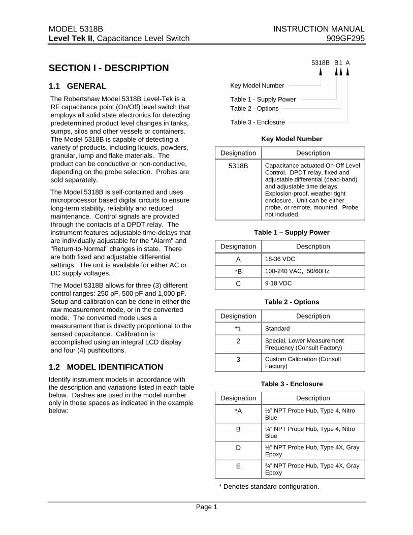
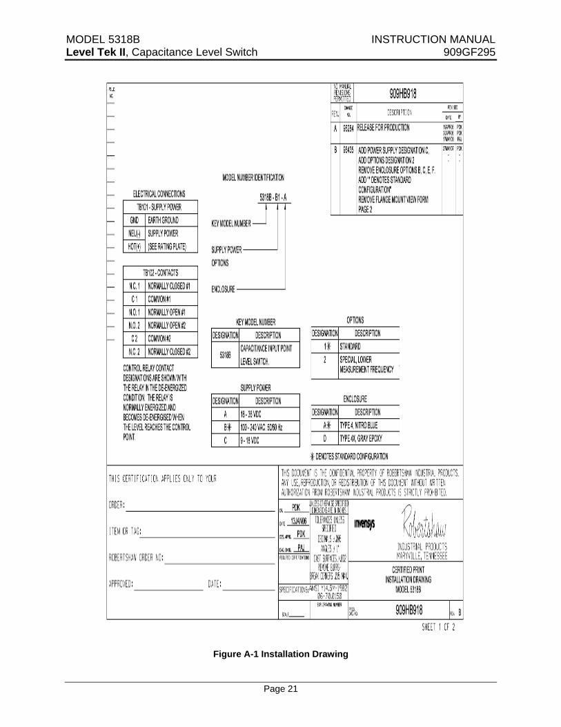
1.2 MODEL IDENTIFICATION Identify instrument models in accordance with the description and variations listed in each table below. Dashes are used in the model number only in those spaces as indicated in the example below:
Key Model Number
Table 1 - Supply PowerTable 2 - Options
Table 3 - Enclosure
5318B B1 A
Key Model Number
Designation Description
5318B Capacitance actuated On-Off Level Control. DPDT relay, fixed and adjustable differential (dead-band) and adjustable time delays. Explosion-proof, weather tight enclosure. Unit can be either probe, or remote, mounted. Probe not included.
Table 1 – Supply Power
Designation Description
A 18-36 VDC
*B 100-240 VAC, 50/60Hz
C 9-18 VDC
Table 2 - Options
Designation Description
*1 Standard
2 Special, Lower Measurement Frequency (Consult Factory)
3 Custom Calibration (Consult Factory)
Table 3 - Enclosure
Designation Description
*A ½” NPT Probe Hub, Type 4, Nitro Blue
B ¾” NPT Probe Hub, Type 4, Nitro Blue
D ½” NPT Probe Hub, Type 4X, Gray Epoxy
E ¾” NPT Probe Hub, Type 4X, Gray Epoxy
* Denotes standard configuration.
MODEL 5318B INSTRUCTION MANUAL Level Tek II, Capacitance Level Switch 909GF295
Page 2
SECTION II – SPECIFICATIONS
2.1 ENVIRONMENTAL Storage Temperature Limits....... -55ºF to +225ºF
(-48ºC to +107ºC)
Operating Temperature Limits ... -40ºF to +160ºF (-40ºC to +70ºC)
Vibration Limits.............................2 g’s to 100 Hz
Operating Humidity Limits ............... 0 to 95% RH (non-condensing)
Weight ..........................................3.5 lbs (1.6 kg)
Shipping Weight ..............................5 lbs (2.3 kg)
2.2 PERFORMANCE Temperature Coefficient.......................0.01pF/ºC
Control Point
Time Delay:
On ALARM........ Adjustable, 0 to 60 seconds
On Return ......... Adjustable, 0 to 60 seconds
Control Range ............................ User Selectable 250, 500, 1,000 pF max
Differential (dead-band):
ON/OFF (Adjustable).......................0.2 pF to 100% of Control Range
ALARM + + (fixed)...............................1.0 pF
ALARM + (fixed) ..................................0.2 pF
ALARM - (fixed)...................................0.2 pF
ALARM - - (fixed).................................1.0 pF
CONTROL (fixed)................................0.2 pF
2.3 ELECTRICAL Supply Voltage:
Standard.............. 100 to 240 VAC, 50/60 Hz
Optional ..................................... 18 - 36 VDC ........................................ 9 - 18 VDC
Supply Power................. 5 watts, 5 VA maximum
Control Relay:
Contacts ...............................DPDT (Form C)
Rating ................................... 5 A @ 28 VDC; 5 A @ 120/240 VAC, non-inductive
2.4 ENCLOSURE Standard ............Explosion proof, cast aluminum
painted with blue polyurethane enamel. Suitable for Class I, Division 1, Groups C & D,
Class II, Division 1, Groups E, F, & G hazardous areas
Dust tight CSA Enclosure 5. Meets Enclosure 4.
Optional.......................... Same as above, except painted with gray epoxy enamel.
Also meets Enclosure 4X
2.5 cETLus APPROVALS UL.................................. Standard 61010-1
CAN/CSA ....................C22.1 NO. 61010-1
RoHS Compliance ........EU Directive 2002/95/EC

MODEL 5318B INSTRUCTION MANUAL Level Tek II, Capacitance Level Switch 909GF295
Page 3
SECTION III – INSTALLATION
3.1 GENERAL
Examine the instrument for possible shipping damages.
IMPORTANT: If for any reason it is determined that parts should be returned to the factory, please notify the nearest Robertshaw Industrial Products sales representative prior to shipment. Each unit must be properly packed to prevent damage. Robertshaw assumes no responsibility for equipment damage in shipment due to improper packaging.
Choose a location in accordance with good instrument practice, avoiding extremes of temperature, humidity, and vibration. (See “Specifications”, Section II)
3.2 PROBE MOUNTING
Robertshaw probes are purchased separately from the instruments and are available in a variety of sizes and types with numerous options for the materials and construction. Each probe should be selected for the specific application in order to insure the best and most reliable operation of the system.
Probes are available with, or without insulation. Insulated probes may be used for liquid, solid or interface detection and can also be used on conductive materials. Bare probes are normally used on non-conductive materials only.
Standard type probes are installed so that the face of the packing gland is flush (or nearly so) with the vessel wall. When installing a probe in a nozzle, recess or open end well, a sheathed probe should be used, with the sheath length equal to the nozzle, recess, or well length. This insures that the “active” portion of the probe is extended into the process area and eliminates potential problems due to build-up in the nozzle, recess, or well.
CAUTION: When installing an insulated probe, care should be taken not to accidental puncture the probe insulation.
3.2.1 HORIZONTAL MOUNTING
Horizontally mounted rod-type probes must be installed in vessels at the desired point of level detection. Horizontally mounted probes provide the closest control (smallest deadband) in that a small change at, or near, the probe will produce a large capacitance change.
On applications involving viscous liquids, or materials, that have a tendency to “cling” or “build-up”, it is recommended that the probe be mounted on a slight downward angle to permit draining of the material from the probe.
Figure 3-1 Horizontally Mounted Instrument
3.2.2 VERTICAL MOUNTING
Vertically mounted rod-type probes should be installed in either the top or bottom of the vessel with the midpoint on the probe corresponding to approximately the desired level detection point.
Vertically installed probes allow a variation in the level detection point up and down the length of the probe by means of the instrument calibration.
Figure 3-1 Vertically Mounted Instrument

MODEL 5318B INSTRUCTION MANUAL Level Tek II, Capacitance Level Switch 909GF295
Page 4
3.3 INSTRUMENT MOUNTING
3.3.1 PROBE MOUNTED
The Model 5318B Level Tek II is designed to be mounted directly on the installed probe assembly as shown in Figure 3-1 and may be mounted or oriented in any position.
Prior to installing the instrument onto the probe, the probe electrical connection pin (included with the instrument) must be installed in the end of the probe as shown in Figure 3.1 to provide the electrical connection between the probe and the instrument. Do not over tighten the probe pin.
Figure 3-3 Probe Mounting
3.3.2 REMOTE MOUNTED
The Model 5318B Level Tek II may also be remotely mounted from the probe using a remote mount cable assembly (sold separately, see SECTION VII -- ACCESSORIES). This cable assembly allows the instrument to be mounted up to 15 feet from the probe. For longer distances consult the factory. Figure 3-2 shows the details of this mounting option.
Figure 3-4 Remote Mounting
MODEL 5318B INSTRUCTION MANUAL Level Tek II, Capacitance Level Switch 909GF295
Page 5
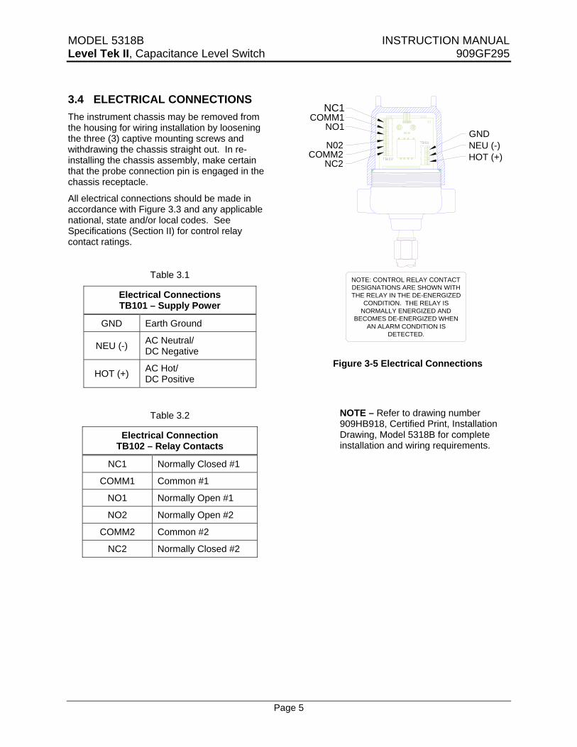
3.4 ELECTRICAL CONNECTIONS The instrument chassis may be removed from the housing for wiring installation by loosening the three (3) captive mounting screws and withdrawing the chassis straight out. In re-installing the chassis assembly, make certain that the probe connection pin is engaged in the chassis receptacle.
All electrical connections should be made in accordance with Figure 3.3 and any applicable national, state and/or local codes. See Specifications (Section II) for control relay contact ratings.
Table 3.1
Electrical Connections TB101 – Supply Power
GND Earth Ground
NEU (-) AC Neutral/ DC Negative
HOT (+) AC Hot/ DC Positive
Table 3.2
Electrical Connection TB102 – Relay Contacts
NC1 Normally Closed #1
COMM1 Common #1
NO1 Normally Open #1
NO2 Normally Open #2
COMM2 Common #2
NC2 Normally Closed #2
GNDNEU (-)HOT (+)
N02
NO1
COMM2NC2
COMM1NC1
NOTE: CONTROL RELAY CONTACT DESIGNATIONS ARE SHOWN WITH THE RELAY IN THE DE-ENERGIZED
CONDITION. THE RELAY IS NORMALLY ENERGIZED AND
BECOMES DE-ENERGIZED WHEN AN ALARM CONDITION IS
DETECTED.
Figure 3-5 Electrical Connections
NOTE – Refer to drawing number 909HB918, Certified Print, Installation Drawing, Model 5318B for complete installation and wiring requirements.

MODEL 5318B INSTRUCTION MANUAL Level Tek II, Capacitance Level Switch 909GF295
Page 6
SECTION IV – OPERATION
4.1 GENERAL All controls and indicators are located on the Measurement PCA. These controls and indicators are accessible by removing the cover of the Model 5318B.
CAUTION: UTILIZATION OF THESE CONTROLS REQUIRES THE REMOVAL OF THE COVER. REMOVING THE COVER VIOLATES THE EXPLOSION-PROOF RATING OF THE ENCLOSURE
4.2 DISPLAYS AND INDICATORS
Figure 4-1 User Controls
4.2.1 LED INDICATORS There are two (2) LED indicators located above the LCD display on the Measurement PCA. The left hand LED (DS203) indicates the health of the Model 5318B. It flashes at a rate of approximately once every two seconds.
The other LED (DS202) indicates the current state of the instrument. It is illuminated when
the Model 5318B is in the ALARM condition, relay de-energized.
4.2.2 LCD DISPLAY A 2-line by 8-character liquid crystal display, LCD, (DS201) is provided to aid in the setup and calibration of the Model 5318B. In normal operations the top line displays the current status and the bottom line displays the current input.
4.3 SWITCHES There are four (4) navigation pushbutton switches located immediately below the LCD display. These switches are identified as follows:
• LEFT [LT] (S203) • UP [UP] (S202) • DOWN [DN] (S205) • RIGHT [RT] (S204).
The function of these switches varies as the user navigates through the menus.
4.4 SETUP
The initial step in putting the Model 5318B into operation is to determine the proper configuration of the instrument. The unit is shipped from the factory with the following default setup values:
Table 4-1 Default Setup Values
Variable Standard Low Freq Custom
High Setpoint 11400 1065 26250
Low Setpoint 14400 1490 26250
Setpoint Mode Adj. Diff Adj. Diff. Control
Failsafe Mode HLFS HLFS LLFS
Alarm Delay 5 5 0
Return Delay 3 3 0
Display Mode RAW RAW RAW
Update Rate 4/sec. 4/sec. 4/sec.
MODEL 5318B INSTRUCTION MANUAL Level Tek II, Capacitance Level Switch 909GF295
Page 7
4.4.1 DETERMINING THE CONTROL RANGE
The first item that must be selected is the control range. The Model 5318B offers three (3) control ranges, but the default value should be sufficient for most typical, horizontally mounted probe, installations.
Applications involving vertically mounted probes may require use of one of the other ranges. The signal range is a function of the probe and the media being sensed. The setpoint(s) must fall within the control range selected.
The control range is determined by selecting the appropriate update rate. The relationship between the control range and update range is as follows:
20* – 250 pF ...................... 4/second 20* – 500 pF ...................... 2/second 125* – 1,000 pF ................. 1/second
* These values are 30 pF for the low frequency version.
EXAMPLE #1:
Consider a vertically mounted Model 740A-B048-N0 probe, 48 inches long used in a conductive liquid. This probe has a gland capacitance of 24 pF and the pF/Ft in air is 4.5.
Assuming that the material being sensed has a dielectric constant of 60 the pF/Ft of the length submerged in the material is 53.
With the product level below the end of the probe the capacitance input to the Model 5318B will be:
A) Gland ...........................24 pF B) Probe (4 x 4.5).............18 pF C) Total ............................42 pF
With all but 6 inches of the probe submerged in the material the capacitance input to the Model 5318B will be:
A) Gland ..................... 24.00 pF B) Probe; In Air
(0.5 x 4.5).................2.25 pF C) Probe; Immersed
(3.5 x 53)............. 185.50 pF D) Total .................... 211.75 pF
These calculations show that the input capacitance for this application will be 42 to 212 pF and the default sampling rate of 4/second (0-250 pF) will be acceptable.
EXAMPLE #2:
Consider a vertically mounted Model 740A-B120-N0 probe, 12 feet long used in water. This probe has a gland capacitance of 24 pF and the pF/Ft in air is 4.5.
Using a dielectric constant of 80 the pF/Ft of the length submerged in the material is 56.
With the product level below the end of the probe the capacitance input to the Model 5318B will be:
A) Gland...........................24 pF B) Probe (12 x 4.5) ..........54 pF C) Total ............................78 pF
With all but 1 foot of the probe submerged in the water the capacitance input to the Model 5318B will be:
A) Gland......................24.00 pF B) Probe; Air
(1 x 4.5) ...................4.50 pF C) Probe; Immersed
(11.5 x 56) ...........644.00 pF D) Total .....................672.50 pF
These calculations show that the capacitance input for this application will be 78 to 673 pF and the sampling rate of 1/second would be required.
4.4.2 CHOOSING THE DISPLAY FORMAT
During normal operation the results of the previous input conversion, measurement, are displayed on the right hand side of the bottom line of the LCD display. The user has the option of displaying this value either as the actual, RAW, measurement or as a converted, CNVRTD, value.
The actual measurement (RAW) is a non-linear function and the converted (CNVRTD) value is linear. Regardless of the display format selected the Model 5318 operates internally using the actual measurement value.
MODEL 5318B INSTRUCTION MANUAL Level Tek II, Capacitance Level Switch 909GF295
Page 8
If the converted format is selected the change in displayed value is proportional to the sensed capacitance.
For Options 1 & 3 a sampling rate of 4/second the display will change ~50 units/1 pF change in the input capacitance. This gives a resolution of ~0.02 pF/unit. For the 2/second sampling rate the change in the display will be ~25 units/pF change or ~0.04 pF/unit. Lastly at the 1/second sampling rate the display change will be ~12.5 units/pF or 0.08 pF/unit.
For Option 2 a sampling rate of 4/second the display will change ~100 units/1 pF change in the input capacitance. This gives a resolution of ~0.01 pF/unit. For the 2/second sampling rate the change will be change in the display will be ~50 units/1 pF change or ~0.02 pF/unit. Lastly at the 1/second sampling rate the display change will be ~25 units/1 pF or ~0.04 pF/unit.
The selection of the display format is up to the user’s preference and does not affect the operation of the instrument. It should be noted that setpoint values will be displayed in the same format as the measurement.
4.4.3 ADJUSTING THE SETUP VALUES Once the sampling rate and display format has been determined the next step will be to adjust the instruments setup values. These values are accessible using the navigation switches located just below the LCD display.
CAUTION: UTILIZATION OF THESE CONTROLS REQUIRES THE REMOVABLE OF THE COVER. REMOVING THE COVER VIOLATES THE EXPLOSION-PROOF RATING OF THE ENCLOSURE
4.4.3.1. ACCESSING THE SETUP VALUES
To access the setup values press the [DN] pushbutton once followed by pressing the [RT] pushbutton once. The display should now show:
High SP XXXXX
Where “XXXXX” represents the currently set High Setpoint value. It should be noted that this value is the result of calibrating the instrument.
This value can be changed, or tweaked, here. Adjusting the setpoint(s) is discussed later in this section.
4.4.3.1.1. SELECTING THE DISPLAY FORMAT
Pressing the [DN] pushbutton six (6) more times will bring the access to the display format variable. The LCD display will initially show:
Display YYYYY
Where “YYYYY” represents the currently selected display format. After a short time the top line of the display will begin scrolling the message:
“Select RAW measured frequency or CONVERTED value proportional to level”
Pressing the [RT] pushbutton once will select this value for changing and the LCD will initially show:
Display Press RT
After a short time the bottom line of the display will begin scrolling the message:
“Press RT to change mode of displayed measurement”
Pressing the [RT] pushbutton once will open the value for change and the LCD will initially show:
Display RAW
After a short time the top line of the display will begin to scroll the message:
“Select RAW measured frequency or CONVERTED value proportional to level”
The [UP] and [DN] pushbuttons can be used to scroll between the two possible value. The currently selected format is identified by an “*” appended to the end of the format. When the desired format is displayed press the [RT] pushbutton to select that format. The display will return to the previous level of the Setup menu.

MODEL 5318B INSTRUCTION MANUAL Level Tek II, Capacitance Level Switch 909GF295
Page 9
4.4.3.1.2. SELECTING THE SAMPLING RATE
Changing the sampling rate can be accessed by pressing the [DN] pushbutton once from the “Display” variable. The display will initially show:
Sampling X/sec
Where “X” represents the currently selected number of updates per second. After a short time the top line of the display will begin to scroll the message:
“Use lower sampling rate only for high capacitance probes”
Pressing the [RT] pushbutton once will select the value and the LCD will initially show:
Sampling Press RT
After a short time the bottom line of the display will begin scrolling the message:
“Press RT to change sampling rate”
Pressing the [RT] pushbutton once will open the value for change and the LCD will initially show:
Sampling X/sec*
The [UP] and [DN] pushbuttons can be used to scroll among the three possible values. The current sampling rate is identified by an “*” appended to the end of the format. When the desired sampling rate is displayed press the [RT] pushbutton to select that rate. The display will return to the previous level of the Setup menu.
4.4.3.1.3. FAIL-SAFE MODE SELECTION
Once the sampling rate and display mode have been set the next logical item to be set is the Fail-Safe Mode. The Model 5318B provides two fail-safe modes; high level (HLFS) and low level (LLFS).
HLFS is the mode in which the “Alarm” condition exists when the sensed level is above the High Setpoint. The alarm then clears, returns to normal, when the level falls bellow the Low Setpoint.
Conversely, LLFS is the mode in which the “Alarm” condition exists when the sensed level is below the Low Setpoint. The alarm then clears when the level rises above the high Setpoint.
To select the required fail-safe mode enter the Setup Menu, from the normal operating mode by pressing the [DN] pushbutton, followed be pressing the [RT] pushbutton. This action will bring you to the first item in the Setup Menu, High SP.
Pressing the [DN] pushbutton three (3) times will bring you to the ‘Alarm ON” variable. The display will initially show:
Alarm ON XXXX
Where XXXX represents the currently selected fail-safe mode. After a short time the top line of the display will begin to scroll the following message:
“Enables alarm – above HIGH setpoint or below LOW setpoint”
Pressing the [RT] pushbutton once will select the value and the LCD will initially show:
Alarm ON Press RT
After a short time the bottom line of the display will begin scrolling the message:
“Press RT to change Alarm setpoint”
Pressing the [RT] pushbutton once will open the value for change and the LCD will initially show:
Alarm ON XXXX*
Where XXXX represents the currently selected fail-safe mode. After a short time the top line of the display will begin to scroll the following message:
“Enables alarm – above HIGH setpoint or below LOW setpoint”
The [UP] and [DN] pushbuttons can be used to scroll among the two possible values. The current fail-safe mode is identified by an “*” appended to the end of the format. When the desired fail-safe mode is displayed press the [RT] pushbutton to select that rate. The display will return to the previous level of the Setup menu.
MODEL 5318B INSTRUCTION MANUAL Level Tek II, Capacitance Level Switch 909GF295
Page 10
4.4.3.1.4. TIME DELAYS
Refer to the Figure 4 - 2 to see the organization of the Setup Menu. There are two (2) more variables that can be adjusted from the Setup Menu. These are the AlarmDly and Ret. Dly, which are the time delays associated with the detecting of an alarm and the clearing of an alarm.
These delays specify the time between the detection of a change in the alarm state and the operating of the relay. When an alarm is detected the time delay will be the time that the alarm condition must exist before the relay is de-activated. When a return-to-normal condition is detected the time delay will be the time the condition must exist before the relay is activated.
The delays can be turned “off” by setting the delay to “00” and the active delay times are 1 to 60 seconds. This allows either or both delays to be turned “Off” and the delay times to be adjusted independently.
4.4.3.1.4.1. TIME DELAY ON ALARM
To select the required time delay enter the Setup Menu, from the normal operating mode by pressing the [DN] pushbutton, followed be pressing the [RT] pushbutton. This action will bring you to the first item in the Setup Menu, High SP.
Pressing the [DN] pushbutton four (4) times will bring you to the “AlarmDly” variable. The display will initially show:
AlarmDly XX
Where XX represents the currently set time delay. After a short time the top line of the display will begin scrolling the message:
“Relay delay when alarm goes ON [seconds]”
Pressing the [RT] pushbutton once will select the variable. The display will initially show:
AlarmDly Press RT
Pressing the [RT] pushbutton will open the variable for change. After a short time the bottom line of the display will begin to scroll the message:
“Press RT to change Alarm delay”
Pressing the [RT] pushbutton will allow the time delay to be changed. The display will initially show:
AlarmDly XX*
Where XX* represents the current time delay setting. After a short time the top line of the display will begin scrolling the message:
“Relay delay when alarm goes ON [seconds]”
The [UP] and [DN] pushbuttons can be used to scroll among the possible values. The current time delay is identified by an “*” appended to the end of the format. When the desired time delay value is displayed press the [RT] pushbutton to select that value. The display will return to the previous level of the Setup menu.
4.4.3.1.4.2. TIME DELAY ON ALARM CLEAR
To select the required time delay enter the Setup Menu, from the normal operating mode by pressing the [DN] pushbutton, followed be pressing the [RT] pushbutton. This action will bring you to the first item in the Setup Menu, High SP.
Pressing the [DN] pushbutton five (5) times will bring you to the “Ret. Dly” variable. The display will initially show:
Ret. Dly XX
Where XX represents the currently set time delay. After a short time the top line of the display will begin scrolling the message:
“Relay delay when alarm goes OFF [seconds]”
Pressing the [RT] pushbutton once will select the variable. The display will initially show:
Ret. Dly Press RT
Pressing the [RT] pushbutton will open the variable for change. After a short time the bottom line of the display will begin to scroll the message:
“Press RT to change return delay”
MODEL 5318B INSTRUCTION MANUAL Level Tek II, Capacitance Level Switch 909GF295
Page 11
Pressing the [RT] pushbutton will allow the time delay to be changed. The display will initially show:
AlarmDly XX*
Where XX* represents the current time delay setting. After a short time the top line of the display will begin scrolling the message:
“Relay delay when alarm goes OFF [seconds]”
The [UP] and [DN] pushbuttons can be used to scroll among the possible values. The current time delay is identified by an “*” appended to the end of the format. When the desired time delay value is displayed press the [RT] pushbutton to select that value. The display will return to the previous level of the Setup menu.
4.5. Performing Instrument Calibration
Once the instrument has been setup the next step is calibrate the instrument to the vessel/process. The Model 5318B provides for several calibration procedures. Some of the procedures require varying the level in the vessel, while others do not. These calibration procedures are as follows:
• Adjustable Differential – this procedure is typically used when the level difference or deadband between the high and low setpoints on vertically mounted probe is desired. Typically used for applications involving motor or pump control.
• Alarm + + – Used to provide single point control. This procedure allows high setpoint calibration when the current level is below the desired setpoint. This procedure is typically used with high dielectric materials and a horizontally mounted probe.
• Alarm + – Same as the procedure above except for use with a low dielectric material.
• Alarm - – Used to provide single point control. This procedure allows low setpoint calibration when the current level is above the desired setpoint. This procedure is typically used with low dielectric materials and a horizontally mounted probe.
• Alarm - - – Same as the procedure above except for use with a High dielectric material.
• Control – Used to set a single setpoint on a probe. This procedure is typically used with a vertically mounted probe.
All of these procedures involve a fixed differential, except Adjustable Differential.
Once the applicable calibration procedure has been selected the calibration is performed using the appropriate description below.
4.5.1. ADJUSTABLE DIFFERENTIAL
This procedure requires physically varying the level in the vessel. This procedure is begun with the level in the vessel at any level.
CAUTION: UTILIZATION OF THESE CONTROLS REQUIRES THE REMOVAL OF THE COVER. REMOVING THE COVER VIOLATES THE EXPLOSION-PROOF RATING OF THE ENCLOSURE
To access this calibration procedure you must first be sure that the instrument’s LCD display is in the normal mode. This can be confirmed by pressing the [LT] pushbutton until the normal display is reached.
To reach the Calibration menu first press the [DN] pushbutton twice, followed by pressing the [RT] pushbutton once. The display will now show:
Step 1 RT
The bottom line will be scrolling the following message:
“Select method of setpoint calibration”

MODEL 5318B INSTRUCTION MANUAL Level Tek II, Capacitance Level Switch 909GF295
Page 12
Press the [RT] pushbutton once to enter the methods submenu. The display will now show:
Exit
The bottom line will be scrolling the following message:
“Scroll down to select mode, then press RT to enter or LT to exit”
Pressing the [DN] pushbutton once will access the desired procedure and the display will show:
AdjDiff
If this is the last procedure used to calibrate the instrument, there will be an “*” at the end of the top line. The bottom line will be scrolling the message:
“Calibrate high and low setpoints separately”
Press the [RT] pushbutton to begin the procedure. The display will show:
First Sp High RT
After a short period of time the top line of the display will scroll the following message:
“Select setpoint for first measurement”
Using the [UP] and [DN] pushbuttons, scroll between the two (2) possible setpoints. When the desired setpoint is displayed press the [RT] pushbutton. If the high setpoint is selected the display will show:
High SP XXXXX
“XXXXX” represents the current measurement. After a short period of time the top line of the display will begin scrolling the message:
“Fill tank to HIGH setpoint, then press RT”
With the level is at the desired setpoint press [RT] to enter the save setpoint mode. The display will show:
Save Sp-? YES RT
Press the [RT] pushbutton to store the value or the [LT] to abort.
After the [RT] pushbutton is pressed the display will show:
Low SP XXXXX
“XXXXX” represents the current measurement. After a short period of time the top line of the display will begin scrolling the message:
“Fill tank to LOW setpoint, then press RT”
With the level is at the desired setpoint press [RT] to enter the save setpoint mode. The display will show:
Save Sp-? YES RT
Press the [RT] pushbutton to store the value or the [LT] to abort.
When the value has been successfully stored the display will return to the normal mode.
4.5.2. ALARM + + AND ALARM +
These two modes are typically used with the level in the vessel is below the horizontally mounted probe. These procedures take the current measured level and subtract a predetermined offset to determine the setpoint. The same value is stored into both setpoints.
This procedure is entered from the normal mode by depressing the [DN] pushbutton twice, followed by pressing the [RT] pushbutton once. The display will show:
Step 1 RT
The bottom line will be scrolling the following message:
“Select method of setpoint calibration”
Press the [RT] pushbutton once to enter the methods submenu. The display will now show:
Exit
The bottom line will be scrolling the following message:
“Scroll down to select mode, then press RT to enter or LT to exit”

MODEL 5318B INSTRUCTION MANUAL Level Tek II, Capacitance Level Switch 909GF295
Page 13
Pressing the [DN] pushbutton twice accesses the ALARM++ procedure. The display will show:
Alarm++ XXXXX
– or –
Pressing the [DN] pushbutton three times will access the Alarm+ procedure. The display will show:
Alarm+ XXXXX
“XXXXX” represents the current measurement. After a short period of time the bottom line of the display will begin scrolling the message:
“Calibrate horizontal probe in air for high dielectric materials”
– or –
“Calibrate horizontal probe in air for low dielectric materials”
Pressing the [RT] pushbutton will enter the save setpoint procedure. The display will show:
High SP XXXXX
“XXXXX” represents the current measurement. After a short period of time the top line of the display will begin scrolling the message:
“Fill tank to HIGH setpoint, then press RT”
Since the level is already at the desired setpoint press [RT] to enter the save setpoint mode. The display will show:
Save Sp-? YES RT
Press the [RT] pushbutton to store the value or the [LT] to abort. After pressing the [RT] pushbutton the setpoint will be stored and the display will return to the normal mode.
4.5.3. ALARM - - AND ALARM -
These two modes are typically used with the level in the vessel is above the horizontally mounted probe. These procedures take the current measured level and add a predetermined offset to determine the setpoint. The same value is stored into both setpoints.
This procedure is entered from the normal mode by depressing the [DN] pushbutton twice, followed by pressing the [RT] pushbutton once. The display will show:
Step 1 RT
The bottom line will be scrolling the following message:
“Select method of setpoint calibration”
Press the [RT] pushbutton once to enter the methods submenu. The display will now show:
Exit
The bottom line will be scrolling the following message:
“Scroll down to select mode, then press RT to enter or LT to exit”
Pressing the [DN] pushbutton four times accesses the ALARM - procedure. The display will show:
Alarm- XXXXX
– or –
Pressing the [DN] pushbutton five times will access the Alarm - - procedure. The display will show:
Alarm - - XXXXX
“XXXXX” represents the current measurement. After a short period of time the bottom line of the display will begin scrolling the message:
“Calibrate submerged horizontal probe for low dielectric materials”
– or –
“Calibrate submerged horizontal probe for high dielectric materials”
Pressing the [RT] pushbutton will enter the save setpoint procedure. The display will show:
Low SP XXXXX

MODEL 5318B INSTRUCTION MANUAL Level Tek II, Capacitance Level Switch 909GF295
Page 14
“XXXXX” represents the current measurement. After a short period of time the top line of the display will begin scrolling the message:
“Fill tank to LOW setpoint, then press RT”
Since the level is already at the desired setpoint press [RT] to enter the save setpoint mode. The display will show:
Save Sp-? YES RT
Press the [RT] pushbutton to store the value or the [LT] to abort. After pressing the [RT] pushbutton the setpoint will be stored and the display will return to the normal mode.
4.5.4. CONTROL
This mode provides a fixed differential at a control point determined by the calibrated level. It is typically used with vertically mounted probes.
The procedure is entered from the normal mode by pressing the [DN] pushbutton twice, followed by the [RT] pushbutton once. The display will show:
Step 1 RT
The bottom line will be scrolling the following message:
“Select method of setpoint calibration”
Press the [RT] pushbutton once to enter the methods submenu. The display will now show:
Exit
The bottom line will be scrolling the following message:
“Scroll down to select mode, then press RT to enter or LT to exit”
Pressing the [DN] pushbutton six times will access the CONTROL procedure. The display will show:
Control
The bottom line of the display will be scrolling the message:
“Calibrate vertical probe with fixed differential”
Pressing the [RT] pushbutton will access the save setpoint procedure. The display will show:
Set SP XXXXX
“XXXXX” represents the current measurement. After a short period of time the top line of the display will begin scrolling the message:
“Fill tank to setpoint, then press RT”
With the level at the desired setpoint, press the [RT] pushbutton. The display will show:
Save Sp-? YES RT
After a short period of time the top line of the display will begin scrolling the message:
“Do you want to save measured setpoint?”
Press the [RT] pushbutton to store the value or the [LT] to abort. After pressing the [RT] pushbutton the setpoint will be stored and the display will return to the normal mode.
4.6. SETPOINT ADJUSTMENTS (TWEAKING)
It is sometimes desirable to make small adjustments to the setpoint(s) once the Model 5318B is in “normal” operation. Setpoint “tweaking” enables changing the setpoint by up to 10%, in 0.1% increments.
4.6.1. SELECTING THE SETPOINT TO BE ADJUSTED
The setpoints are adjusted from the setup menu. The adjustment procedure is entered from the normal mode by pressing the [DN] pushbutton once, followed by pressing the [RT] pushbutton once. The display will show:
High SP XXXXX

MODEL 5318B INSTRUCTION MANUAL Level Tek II, Capacitance Level Switch 909GF295
Page 15
“XXXXX” represents the current measurement. If the low setpoint is to be adjust the press the [DN] once. The display will show:
Low SP XXXXX
“XXXXX” represents the current measurement.
4.6.2. ADJUSTING THE SETPOINT
Once the desired setpoint is displayed, the adjustment procedure is entered by pressing the [RT] pushbutton once. For these instructions we will assume the low setpoint is to be adjusted. After a short period of time the bottom line of the display will scroll the message:
“Press RT to adjust setpoint”
Pressing the [RT] pushbutton will begin the adjustment procedure. The display will show:
Low SP DN 0.0%
After a short period of time the top line of the display will scroll the following message:
“Press RT to save or LT to quit”
At this point the [UP] and [DN] pushbuttons can be used to determine the amount the setpoint is to be changed. The amount of change will scroll in increments of 0.1%.
The lower line of the display will change to show the amount of change (YY X.X%). Where “YY” is the direction of the change, “DN” or “UP” and “X.X%” is the amount of change to be applied.
Pressing the [RT] pushbutton will apply the change and the display will return to the display of the adjusted setpoint value:
Low SP XXXXX
“XXXXX” represents the adjusted setpoint value.
- Or -
Pressing the [LT] pushbutton will exit the adjustment procedure without making any
change and the display will return to the display of the setpoint value:
Low SP XXXXX
“XXXXX” represents the unadjusted setpoint value.
4.6.3. RETURNING TO THE NORMAL DISPLAY MODE
Pressing the [LT] pushbutton twice will return the display to the normal operating mode.
4.7. RECOVERING THE FACTORY DEFAULT SETTINGS
Under certain conditions it may be desirable to restore the instrument to its factory default settings.
Care should be taken when executing this feature since it will erase all existing settings and calibration.
This function can be found at the end of the Setup Menu. It is accessed from the normal mode by pressing the [DN] pushbutton once, the [RT] pushbutton once and the [DN] pushbutton eight times. The display will show:
CalibCLR NO
After a short period of time the top line of the display will scroll the message:
“Selecting RESET erase current settings and calibration”
Pressing the [RT] pushbutton will enter the function. The display will show:
CalibCLR Press RT
After a short period of time the bottom line of the display will scroll the message:
“Press RT to erase calibration and set default setup”
MODEL 5318B INSTRUCTION MANUAL Level Tek II, Capacitance Level Switch 909GF295
Page 16
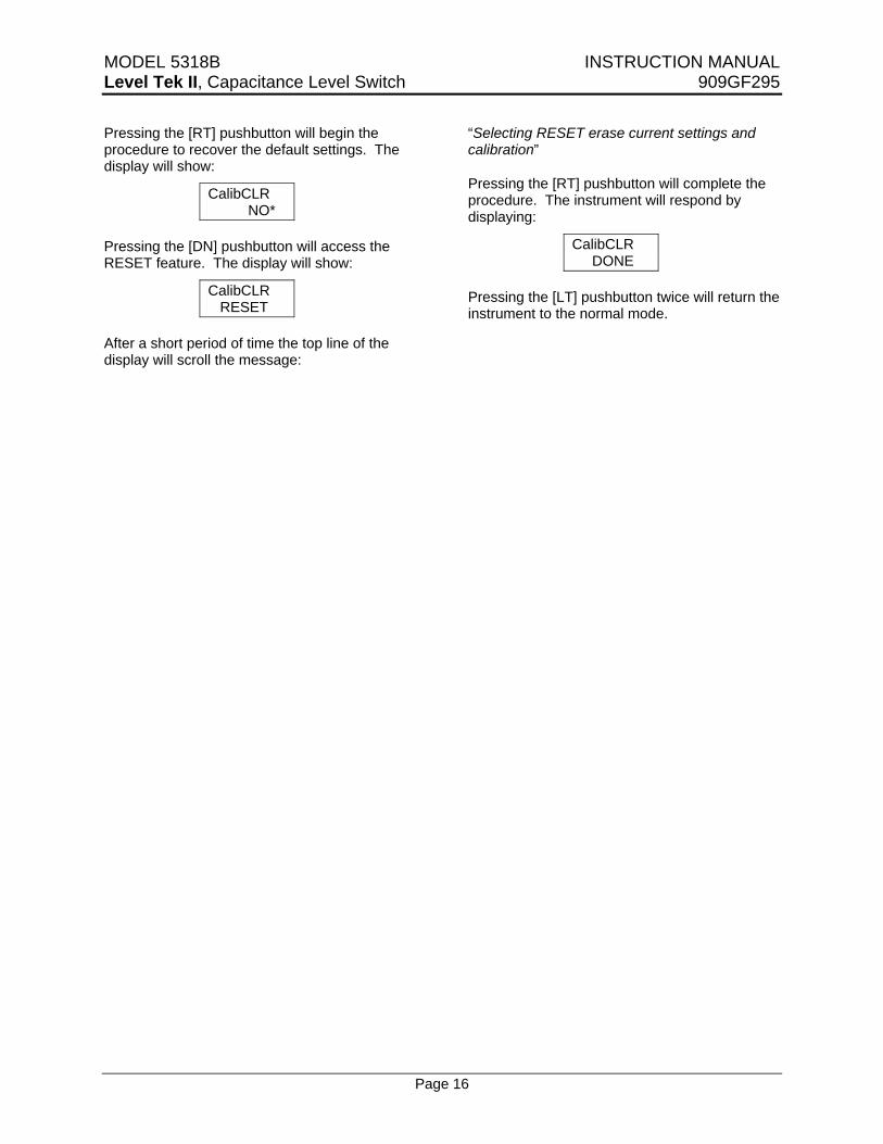
Pressing the [RT] pushbutton will begin the procedure to recover the default settings. The display will show:
CalibCLR NO*
Pressing the [DN] pushbutton will access the RESET feature. The display will show:
CalibCLR RESET
After a short period of time the top line of the display will scroll the message:
“Selecting RESET erase current settings and calibration”
Pressing the [RT] pushbutton will complete the procedure. The instrument will respond by displaying:
CalibCLR DONE
Pressing the [LT] pushbutton twice will return the instrument to the normal mode.
MODEL 5318B INSTRUCTION MANUAL Level Tek II, Capacitance Level Switch 909GF295
Page 17
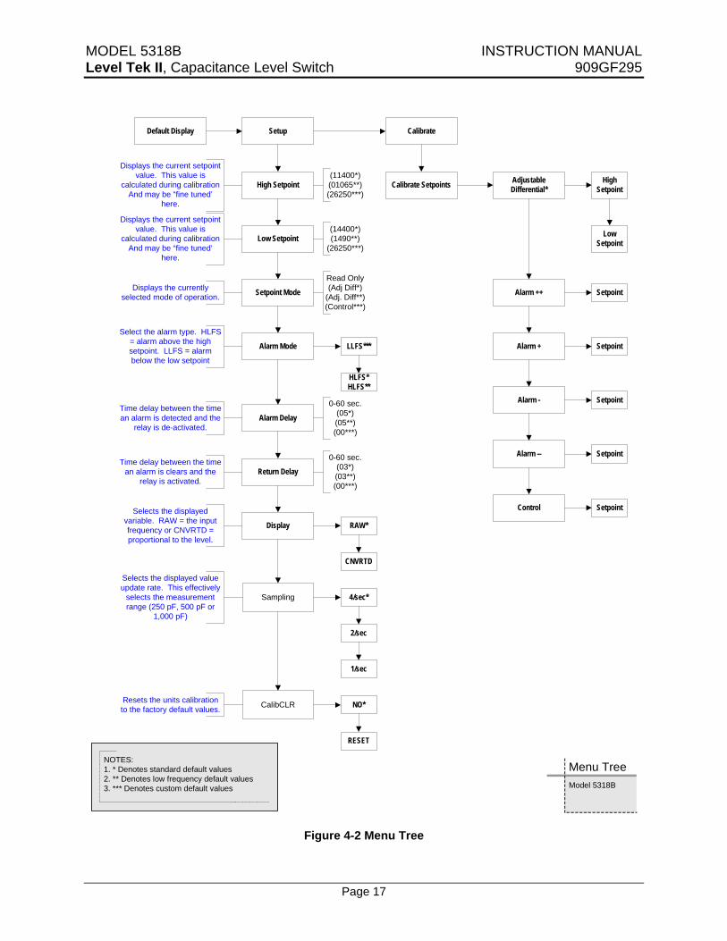
Default Display Setup Calibrate
High Setpoint
Low Setpoint
Alarm Mode LLFS***
HLFS*HLFS**
Alarm Delay
Return Delay
Display RAW*
CNVRTD
(11400*)(01065**)(26250***)
(14400*)(1490**)
(26250***)
Setpoint Mode
Read Only(Adj Diff*)
(Adj. Diff**)(Control***)
Calibrate Setpoints AdjustableDifferential*
High Setpoint
Low Setpoint
Alarm ++ Setpoint
Alarm + Setpoint
Alarm - Setpoint
Alarm -- Setpoint
Control Setpoint
Model 5318B
Menu Tree
0-60 sec.(05*)(05**)(00***)
0-60 sec.(03*)(03**)(00***)
Sampling 4/sec*
2/sec
1/sec
CalibCLR NO*
RESET
Selects the displayed value update rate. This effectively
selects the measurement range (250 pF, 500 pF or
1,000 pF)
Selects the displayed variable. RAW = the input frequency or CNVRTD = proportional to the level.
Resets the units calibration to the factory default values.
Time delay between the time an alarm is detected and the
relay is de-activated.
Time delay between the time an alarm is clears and the
relay is activated.
Select the alarm type. HLFS = alarm above the high setpoint. LLFS = alarm below the low setpoint
Displays the current setpoint value. This value is
calculated during calibrationAnd may be “fine tuned’
here.
Displays the current setpoint value. This value is
calculated during calibrationAnd may be “fine tuned’
here.
Displays the currently selected mode of operation.
NOTES:1. * Denotes standard default values2. ** Denotes low frequency default values3. *** Denotes custom default values
Figure 4-2 Menu Tree
MODEL 5318B INSTRUCTION MANUAL Level Tek II, Capacitance Level Switch 909GF295
Page 18
SECTION V – TROUBLE SHOOTING
5.1 STATUS LED
The Model 5318B is constantly checking its status. The STATUS LED (DS203) will flash at the rate of approximately once every two (2) seconds to indicate that the electronics are functioning correctly.
If the LED is not flashing the instrument may be reset by removing power from the instrument for a minimum of 10 seconds. If the LED is still not flashing contact your nearest ROBERTSHAW Industrial Products Representative for replacement parts.
5.2 ERROR CODES
There are also a number of Error Codes that are displayed to indicate various detected out of range values.
5.2.1. ERROR 01 – Reserved
This error code is reserved for future use.
5.2.2. ERROR 02 – Measurement Too High
This error code alerts that the current raw measurement value is too high (the sensed capacitance is too low).
The most common cause of this error is an open circuit to the probe and the most common cause is a failure to install the probe pin.
If the probe pin is installed contact your nearest ROBERTSHAW Industrial Products Representative for assistance.
5.2.3. ERROR 03 – Measurement Too Low
This error code alerts that the current raw measurement is too low (the sensed capacitance is too high).
The most common cause of this error is improper control range selection. If this error occurs refer to paragraph 4.4.1.
Another cause of this error is a shorted probe. To check for a shorted probe follow the following procedure:
• Remove power from the instrument.
• Remove the cover from the instrument.
• Remove the electronics assembly from the base of the housing by loosening the three (3) captive screws and pulling it straight up, out of the base.
• With a Multi-Meter measure the resistance between the probe pin and the base. This value should be greater than 3 Megohms.
If changing the control range or a shorted probe is detected, contact your nearest ROBERTSHAW Industrial Products Representative for assistance.
5.2.4. ERROR 04 – Low Setpoint Too Close or Reversed.
This error code alerts that the low setpoint level being calibrated is higher than the high setpoint level.
5.2.5. ERROR 05 – High Setpoint Too Close or Reversed
This error code alerts that the high setpoint level being calibrated is lower than the low setpoint level.

MODEL 5318B INSTRUCTION MANUAL Level Tek II, Capacitance Level Switch 909GF295
Page 19
SECTION VI – SPARE PARTS PART NUMBER DESCRIPTION USED ON
044KX350-11 PCA, MEASUREMENT & HMI, STD 5318B-x1-x
044KX350-21 PCA, MEASUREMENT & HMI, LOW FREQUENCY 5318B-x2-x
044KX350-31 PCA, MEASUREMENT & HMI, CUSTOM CALIBRATION 5318B-x3-x
044KX353-01 PCA, POWER SUPPLY & RELAY, AC POWERED 5318B-Ax-x
044KX353-02 PCA, POWER SUPPLY & RELAY, 18-36 VDC 5318B-Bx-x
044KX353-03 PCA, POWER SUPPLY & RELAY, 9-18 VDC 5318B-Cx-x
044KX355-11 ELECTRONICS ASSY, AC POWERED , STD 5318B-B1-x
044KX355-12 ELECTRONICS ASSY, 18-36 VDC, STD 5318B-A1-x
044KX355-13 ELECTRONICS ASSY, 9-18 VDC POWERED, STD 5318B-C1-x
044KX355-21 ELECTRONICS ASSY, AC POWERED , SPECIAL 5318B-B2-x
044KX355-22 ELECTRONICS ASSY, 18-36 VDC, LOW FREQ 5318B-A2-x
044KX355-23 ELECTRONICS ASSY, 9-18 VDC, LOW FREQ 5318B-C2-x
044KX355-31 ELECTRONICS ASSY, AC POWERED, CUSTOM CAL. 5318B-B3-x
130KB051-02 FUSE, DC POWERED UNITS 5318B-Ax-x 5318B-Cx-X
130KB051-03 FUSE, AC POWERED UNITS 5318B-Bx-x
909GM168 KIT, PROBE TERMINATION (INCLUDES PROBE PIN & SCREWDRIVER)
ANY
909GM170 KIT, SUPPRESSION (FOR INDUCTIVE LOADS) ANY
560KB051-57 O-RING, COVER ALL
MODEL 5318B INSTRUCTION MANUAL Level Tek II, Capacitance Level Switch 909GF295
Page 20
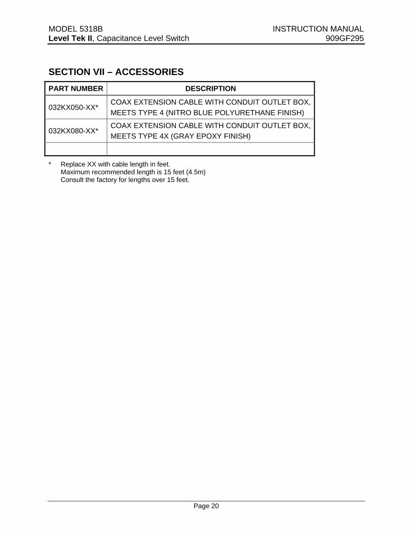
SECTION VII – ACCESSORIES PART NUMBER DESCRIPTION
032KX050-XX* COAX EXTENSION CABLE WITH CONDUIT OUTLET BOX, MEETS TYPE 4 (NITRO BLUE POLYURETHANE FINISH)
032KX080-XX* COAX EXTENSION CABLE WITH CONDUIT OUTLET BOX, MEETS TYPE 4X (GRAY EPOXY FINISH)
* Replace XX with cable length in feet. Maximum recommended length is 15 feet (4.5m) Consult the factory for lengths over 15 feet.
MODEL 5318B INSTRUCTION MANUAL Level Tek II, Capacitance Level Switch 909GF295
Page 21
Figure A-1 Installation Drawing

MODEL 5318B INSTRUCTION MANUAL Level Tek II, Capacitance Level Switch 909GF295
Page 22
Figure A-1 Installation Drawing -Continued
MODEL 5318B INSTRUCTION MANUAL Level Tek II, Capacitance Level Switch 909GF295
Page 23
THIS PAGE IS INTENTIONALLY BLANK

Q-4179 (11-14) Printed in USA