lexicon studio studio_user_guide_302.pdf… · 1 1 lexicon studio 12t system user guide getting...
TRANSCRIPT
1 2 T S y s t e m U s e r G u i d e
Unpacking and InspectionAfter unpacking the12T system modules, save all packing materials in case you ever need to ship the units. Thoroughly inspect the modules andpacking materials for signs of damage. Report any damage to the carrier at once; report equipment malfunction to your dealer.
Lexicon Part #070-12131
Copyright 1998, Lexicon Inc.All Rights Reserved.
Printed in the U.S.A.
Lexicon Inc.3 Oak ParkBedford MA 01730-1441Telephone 781-280-0300Fax 781-280-0490www.lexicon.com
NoticeThis equipment generates and uses radio frequency energy and if not installed and used properly, that is, in strict accordance with the manufacturer'sinstructions, may cause interference to radio and television reception. It has been type tested and found to comply with the limits for a Class Acomputing device in accordance with the specifications in Subpart J of Part 15 of FCC Rules, which are designated to provide reasonable protectionagainst such interference in a residential installation. However, there is no guarantee that interference will not occur in a particular installation. Ifthis equipment does cause interference to radio or television reception, which can be determined by turning the equipment OFF and ON, the useris encouraged to try to correct the interference by one or more of the following measures:
Reorient the receiving antennaRelocate the computer with respect to the receiverMove the computer away from the receiverPlug the computer into a different outlet so that the computer and receiver are on different branch circuits.
If necessary, the user should consult the dealer or an experienced radio/television technician for additional suggestions. The user may find thefollowing booklet prepared by the Federal Communications Commission helpful:
"How to identify and Resolve Radio/TV Interference Problems."
This booklet is available from the U.S. Government Printing Office, Washington, DC 20402, Stock No. 004-000-00345-4.
Le présent appareil numérique n'émet pas de bruits radioélectriques dépassant les limites applicables aux appareils numériques de la class Aprescrites dans le Règlement sur le brouillage radioélectrique édicté par le ministère des Communications du Canada.
This triangle, which appears onyour component, alerts you tothe presence of uninsulated,dangerous voltage inside theenclosure... voltage that may besufficient to constitute a risk ofshock.
CAUTIONRISK OF ELECTRIC SHOCKRISK OF ELECTRIC SHOCK
DO NOT OPENDO NOT OPEN
This triangle, which appears onyour component, alerts you toimportant operating and main-tenance instructions in this ac-companying literature.
1 2 T S y s t e m U s e r G u i d e

i
Table of Contents1 Getting Started
Introduction .......................................................... 1System Requirements .......................................... 1
Versions of Windows ..................................... 2High Performance Systems ........................... 2SCSI vs. IDE .................................................. 3
2 InstallationPrecautions .......................................................... 5Hardware Installation ........................................... 6
Setup ............................................................. 6Mount the PC-90 Card
onto the Core-32 Card ............................. 6Attach the PCI Extender ................................ 5Install the Core-32/PC-90 Assemby .............. 7Connect the LDI-12T Interface
to Audio Sources ...................................... 9Software Installation ........................................... 10
Install Supported Third PartyAudio Software ....................................... 10
Install the ASIO Lexicon Studio Driverfor Windows 95 ...................................... 10
Install the PC-90 Software for Windows 95 . 10System Connections .......................................... 11
Front Panel Connections ............................. 11Rear Panel Connections .............................. 12Typical Configurations ................................. 12
3 Core-32 BasicsSignal Routing .................................................... 15Core-32 Control Panel ....................................... 16
Ctrl I/O ......................................................... 17Reverb ............................................................... 19Punch Record .................................................... 22
Configuring the Punch Feature .................... 22The Mix Level control ................................... 23
Timecode and Synchronization .......................... 24Setting Up Cubase to Sync to Timecode ..... 25Setting the Audio Sync Clock Reference ..... 25Sample Rates .............................................. 26Word Clock .................................................. 26Word Clock Sources .................................... 27Recording .................................................... 27
4 Using the PC-90Basic Operation .................................................. 29
The Interface................................................ 29Inserting a Plug-In ........................................ 30Routing an Audio Channel through
the PC-90 ............................................... 30Selecting PC-90 and Making Settings ......... 31Naming Effects ............................................ 33Saving Effects .............................................. 33Loading Effects ............................................ 34Editing Effects .............................................. 34
Beyond the Basics ............................................. 35Routing a Plug-In ......................................... 35Automating the PC-90 ................................. 39
5 ReferencePC-90 Algorithms ............................................... 41
Ambience ..................................................... 41Chamber ...................................................... 42Concert Hall ................................................. 43Inverse ......................................................... 43Room ........................................................... 44
The Parameters ................................................. 45Chorus ......................................................... 45Crossover .................................................... 45Decay........................................................... 45Decay Lvl ..................................................... 45Definition ...................................................... 45Diffusion ....................................................... 46Duration ....................................................... 46Echo Delays ................................................. 46Echo Feedback ............................................ 46Effects Mix ................................................... 46HF Rolloff ..................................................... 46Infinite .......................................................... 47Input Lvl ....................................................... 47Link .............................................................. 47Mid RT and Bass Mult ................................. 47Pre Delay ..................................................... 47Range and Rate ........................................... 47
Reverb Level ................................................ 48Reflect Delays .............................................. 48Reflect Levels .............................................. 48Shape, Spread ............................................. 48Size .............................................................. 48Slope ............................................................ 49Spin .............................................................. 49Treble Dcy ................................................... 49
Preset Descriptions ............................................ 50Notes on Preset Design ............................... 50
Appendix AThird Party Support ............................................A1
Steinberg Cubase VST ................................ A1
Appendix BTroubleshooting .................................................B1
Installation Troubleshooting ......................... B1PC Troubleshooting .....................................B2Optimizing Windows 95 for
Audio Applications.................................. B4Common Problems and Solutions ...............B7Poor System Performance ........................... B8Pops and Clicks ........................................... B8
Appendix CSpecifications .................................................... C1
ii

Lexicon Part # 070-12131
Lexicon Inc.3 Oak ParkBedford MA 01730-1441Telephone 781-280-0300Fax 781-280-0490www.lexicon.com
1
1
Getting StartedLexicon Studio 12T System User Guide
Getting Started
IntroductionThank you for your purchase of a Lexicon Studio system. Lexicon Studio provides a line ofprofessional hardware components for computers that provides uncompromised audio quality andextensive processing capability. This family of products is designed to allow you to tailor your workingenvironment to your needs. Lexicon Studio provides I/O options, DSP, signal routing, and synchro-nization for industry leading software.
Although written to accommodate both novice and expert users, this manual assumes somefamiliarity with the software application you have selected to interface with Lexicon Studio. If you havequestions concerning the use of your software application, refer to the manufacturer’s user manualbefore using your Lexicon Studio system.
A “Read Me” file containing late-breaking information is provided on diskette with your Lexicon Studiosystem, along with On-Line documentation for the PC-90.
System RequirementsThe following system is recommended as the minimum for working with Lexicon Studio and SteinbergCubase Audio VST:
• 166 MHz Pentium Processor or compatible equivalent (Please visit our Web site for the latestinformation on compatibility.)
• 64 MB of RAM
• Audio-capable disk drive
• Microsoft Windows — 95™ or later
1
Getting Started
2
2
Lexicon
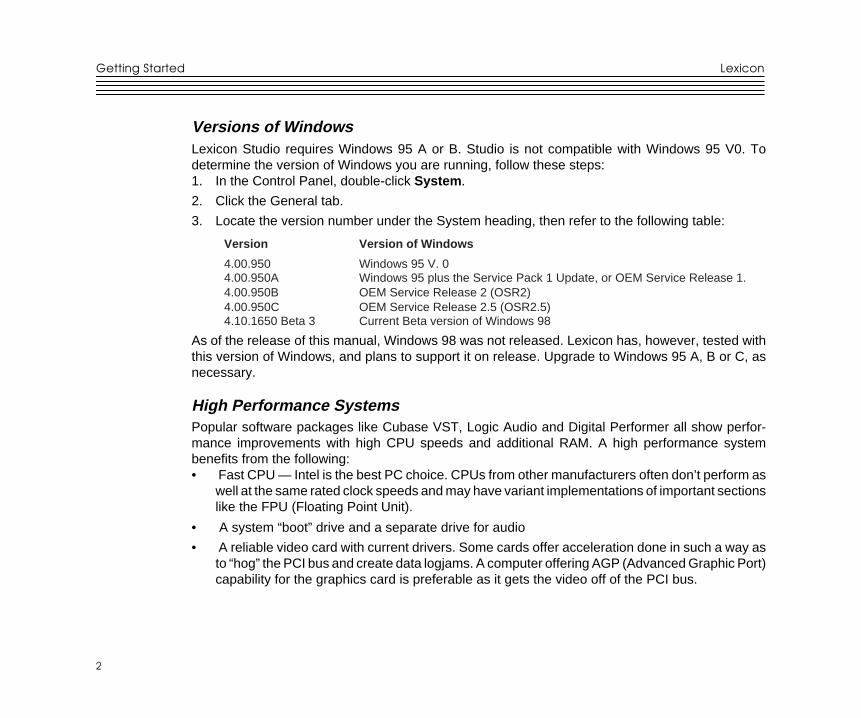
Versions of WindowsLexicon Studio requires Windows 95 A or B. Studio is not compatible with Windows 95 V0. Todetermine the version of Windows you are running, follow these steps:1. In the Control Panel, double-click System .
2. Click the General tab.
3. Locate the version number under the System heading, then refer to the following table:
Version Version of Windows
4.00.950 Windows 95 V. 04.00.950A Windows 95 plus the Service Pack 1 Update, or OEM Service Release 1.4.00.950B OEM Service Release 2 (OSR2)4.00.950C OEM Service Release 2.5 (OSR2.5)4.10.1650 Beta 3 Current Beta version of Windows 98
As of the release of this manual, Windows 98 was not released. Lexicon has, however, tested withthis version of Windows, and plans to support it on release. Upgrade to Windows 95 A, B or C, asnecessary.
High Performance SystemsPopular software packages like Cubase VST, Logic Audio and Digital Performer all show perfor-mance improvements with high CPU speeds and additional RAM. A high performance systembenefits from the following:• Fast CPU — Intel is the best PC choice. CPUs from other manufacturers often don’t perform as
well at the same rated clock speeds and may have variant implementations of important sectionslike the FPU (Floating Point Unit).
• A system “boot” drive and a separate drive for audio
• A reliable video card with current drivers. Some cards offer acceleration done in such a way asto “hog” the PCI bus and create data logjams. A computer offering AGP (Advanced Graphic Port)capability for the graphics card is preferable as it gets the video off of the PCI bus.
3
3
Getting StartedLexicon Studio 12T System User Guide
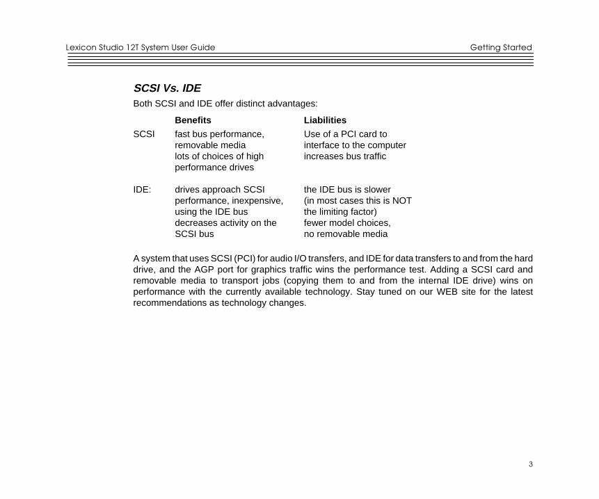
SCSI Vs. IDEBoth SCSI and IDE offer distinct advantages:
Benefits Liabilities
SCSI fast bus performance, Use of a PCI card toremovable media interface to the computerlots of choices of high increases bus trafficperformance drives
IDE: drives approach SCSI the IDE bus is slowerperformance, inexpensive, (in most cases this is NOTusing the IDE bus the limiting factor)decreases activity on the fewer model choices,SCSI bus no removable media
A system that uses SCSI (PCI) for audio I/O transfers, and IDE for data transfers to and from the harddrive, and the AGP port for graphics traffic wins the performance test. Adding a SCSI card andremovable media to transport jobs (copying them to and from the internal IDE drive) wins onperformance with the currently available technology. Stay tuned on our WEB site for the latestrecommendations as technology changes.
Getting Started
4
4
Lexicon
5
5
InstallationLexicon Studio 12T System User Guide
InstallationDepending on your computer, installation of your Lexicon Studio system should take about 20minutes. Please read through the entire procedure before performing the installation.
Precautions• Turn off and unplug your computer.
• Use the anti-static wrist strap provided with your system and make sure that you are groundedduring the entire installation process to prevent static charges that can damage components.
• Put the anti-static bags containing your cards near your computer to avoid walking around witha card after it is removed from its bag (and generating static electricity).
• Before handling any Lexicon Studio cards, discharge any personal static electricity that may beon your clothes or body by touching a grounded metal surface, such as the power supply caseinside your computer.
• Handle the cards only by their edges, as you would a CD. Avoid touching the pins on the bottomedge of the cards.
• Save the anti-static bags containing your Core-32 System card and PC-90 module. Theseprevent static electricity from damaging sensitive electronic components on the cards. Whenevercards are removed from your computer, they should be stored in these bags.
2
Installation
6
6
Lexicon
Hardware Installation
Setup1. Put on the anti-static wrist strap.
2. Place the foam from your Lexicon Studio package on top of a work surface next to your computer.(Any flat piece of static-safe foam with similar dimensions to the Core-32 card can be used).
3. Make sure that you computer is properly shut down and unplugged.
4. Remove the computer top cover and PCI slot cover(s) for the slots you’ve chosen for your LexiconStudio cards. If you do not know how to open your computer, consult your computer owner’smanual.
5. Touch the computer power supply case to discharge any personal static electricity.
6. Remove the Core-32 from its anti-static bag, holding the card only by its edges. Be careful to avoidtouching the pins on the bottom edge of the card. Place the Core-32 bag on top of the foam andplace the card on the foam with the white PC-90 connector facing up as shown below.
Mount the PC-90 card onto the Core-32 cardThe PC-90 module can only be mounted onto a Lexicon Studio Core-32 system card. Attempting toattach your PC-90 to any other type of PCI card may damage your PC-90 module.
1. Touch the computer power supply case to discharge any personal static.
2. Remove the PC-90 module from its anti-static bag, holding the card only by its edges. Place thebag on your work surface next to your computer and place the PC-90 on it with its white connectorfacing up.
3. Pick up the PC-90 card and orient it so that the connector side faces away from the palm of yourhand.
4. Pick up the Core-32 card in your other hand. Orient the cards with their connector sides facingeach other and align the connectors at the top of each card. Firmly press the cards together untilthey connect fully. The holes on the edges of the Core-32 card should be aligned with thestandoffs on the PC-90 card.
7
7
InstallationLexicon Studio 12T System User Guide
5. Once the cards are mated, place the assembly, with the Core-32 card on top, onto the Core-32anti-static bag. Use the four screws provided to attach the PC-90 to the Core-32 card. Do notovertighten the screws as you may damage the PC board.
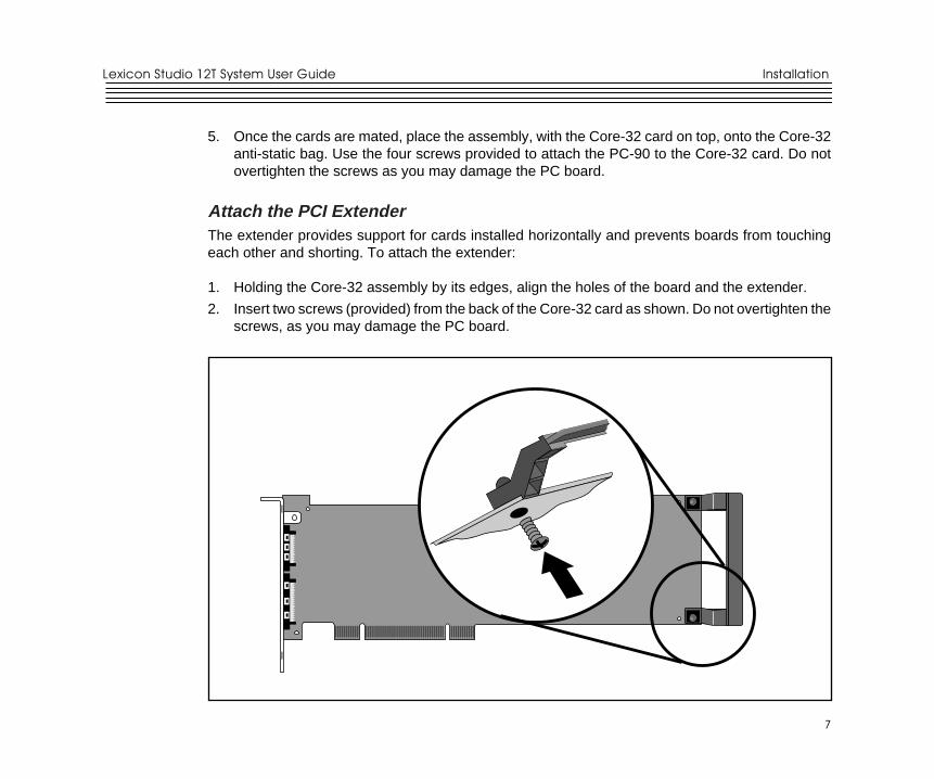
Attach the PCI ExtenderThe extender provides support for cards installed horizontally and prevents boards from touchingeach other and shorting. To attach the extender:
1. Holding the Core-32 assembly by its edges, align the holes of the board and the extender.
2. Insert two screws (provided) from the back of the Core-32 card as shown. Do not overtighten thescrews, as you may damage the PC board.
Installation
8
8
Lexicon
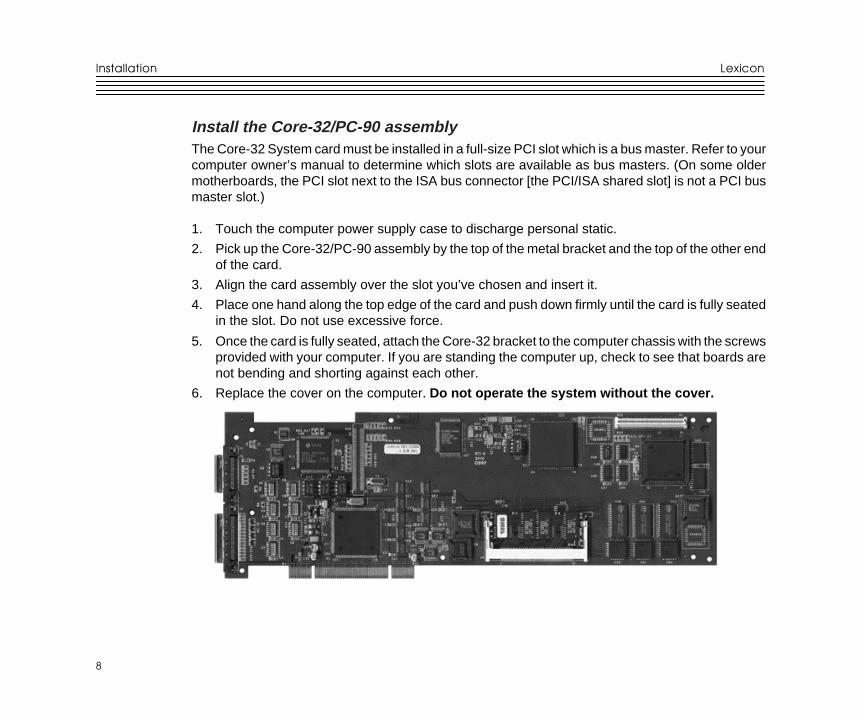
Install the Core-32/PC-90 assemblyThe Core-32 System card must be installed in a full-size PCI slot which is a bus master. Refer to yourcomputer owner’s manual to determine which slots are available as bus masters. (On some oldermotherboards, the PCI slot next to the ISA bus connector [the PCI/ISA shared slot] is not a PCI busmaster slot.)
1. Touch the computer power supply case to discharge personal static.
2. Pick up the Core-32/PC-90 assembly by the top of the metal bracket and the top of the other endof the card.
3. Align the card assembly over the slot you’ve chosen and insert it.
4. Place one hand along the top edge of the card and push down firmly until the card is fully seatedin the slot. Do not use excessive force.
5. Once the card is fully seated, attach the Core-32 bracket to the computer chassis with the screwsprovided with your computer. If you are standing the computer up, check to see that boards arenot bending and shorting against each other.
6. Replace the cover on the computer. Do not operate the system without the cover.
9
9
InstallationLexicon Studio 12T System User Guide
Connect the LDI-12T Interface to Audio SourcesCables/Connections
1. Use only the proprietary Lexicon cable (provided) to connect the Core-32 card to the LDI-12TInterface.
2. With both the computer and the LDI-12T powered down, attach the cable between the lowerconnector on the back of the Core-32 card and the Computer port on the LDI-12T rear panel.
3. Connect the 9V connector to the AC Power port on the rear panel of the LDI-12T, and plug theother end into a wall socket.
The LDI-12T supports various formats of analog and digital I/O. Make certain your cables are thecorrect types prior to connection. (Analog XLR connectors are +4dBu balanced (Pin 2 hot) , analogRCA connectors are –10dBV unbalanced). To select a source for input or output within the applicationsoftware, refer to the documentation provided with your particular software package
Installation
10
10
Lexicon
Software Installation
Install Supported Third Party Audio SoftwareLexicon Studio requires compatible front-end software (such as Cubase Audio VST) to operate.Please refer to your particular software installation guide for assistance. As Lexicon Studio installssoftware within directories of your front-end software, you should install your audio software first andverify that it launches properly before installing Lexicon Studio (even though it will not be audio-capable until installation of the Lexicon Studio system).
Install the ASIO Lexicon Studio Driver for Windows 951. With the Core-32 assembly installed, power up your computer and your LDI-12T interface. Once
your computer is fully booted, Windows 95 will identify a new PCI multimedia device (In the eventof booting problems, refer to the troubleshooting section of this manual).
2. Insert Disk 1: Lexicon Studio Drivers. Windows 95 will search the floppy drive for the .inf file. Oncethis is found, click Finish .
3. Restart your computer.
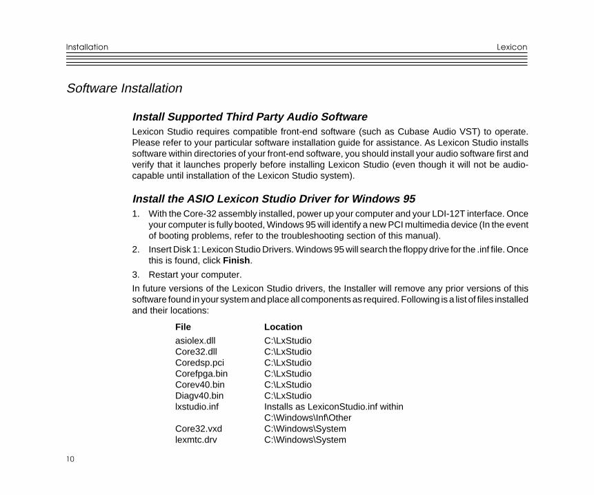
In future versions of the Lexicon Studio drivers, the Installer will remove any prior versions of thissoftware found in your system and place all components as required. Following is a list of files installedand their locations:
File Location
asiolex.dll C:\LxStudioCore32.dll C:\LxStudioCoredsp.pci C:\LxStudioCorefpga.bin C:\LxStudioCorev40.bin C:\LxStudioDiagv40.bin C:\LxStudiolxstudio.inf Installs as LexiconStudio.inf within
C:\Windows\Inf\OtherCore32.vxd C:\Windows\Systemlexmtc.drv C:\Windows\System
11
11
InstallationLexicon Studio 12T System User Guide
Install the PC-90 Software for Windows 951. Insert Disk 2: PC-90 Software Disk
2. Open the disk and double-click on Setup.exe to launch the Installer.
3. Make certain that the Installer is directed toward the desired plug-in folders (example:c:\..\Cubase Audio VST\vstplugins)
4. Click Next to install PC-90 software
5. Click Finish to complete the PC-90 software installation.
6. Restart your computer
Installing the PC-90 software will file it within the registry. To remove or update this software, removethe PC-90 install by using the Add/Remove Programs control panel, highlighting PC-90 Install , andselecting Remove . This control panel is located at Start/Settings/Control Panel/Add/RemovePrograms.
System ConnectionsThe Lexicon Studio 12T system has the following signal connections.
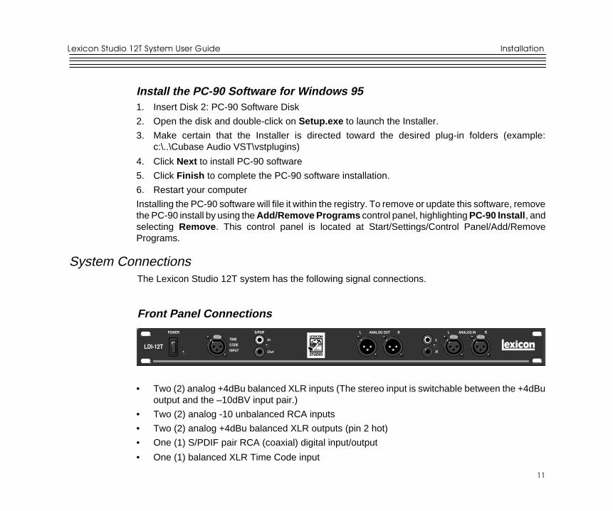
Front Panel Connections
• Two (2) analog +4dBu balanced XLR inputs (The stereo input is switchable between the +4dBuoutput and the –10dBV input pair.)
• Two (2) analog -10 unbalanced RCA inputs
• Two (2) analog +4dBu balanced XLR outputs (pin 2 hot)
• One (1) S/PDIF pair RCA (coaxial) digital input/output
• One (1) balanced XLR Time Code input
LDI-12T
L
R
In
Out
S/PDIF ANALOG OUT RL ANALOG IN RL
TIME
CODE
INPUT
POWER
PUSHPUSH PUSHPUSHPUSHPUSH
Installation
12
12
Lexicon
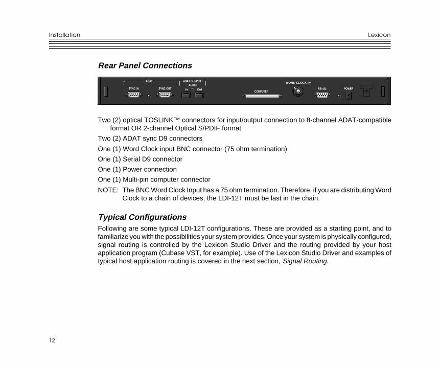
Rear Panel Connections
Two (2) optical TOSLINK™ connectors for input/output connection to 8-channel ADAT-compatibleformat OR 2-channel Optical S/PDIF format
Two (2) ADAT sync D9 connectors
One (1) Word Clock input BNC connector (75 ohm termination)
One (1) Serial D9 connector
One (1) Power connection
One (1) Multi-pin computer connector
NOTE: The BNC Word Clock Input has a 75 ohm termination. Therefore, if you are distributing WordClock to a chain of devices, the LDI-12T must be last in the chain.
Typical ConfigurationsFollowing are some typical LDI-12T configurations. These are provided as a starting point, and tofamiliarize you with the possibilities your system provides. Once your system is physically configured,signal routing is controlled by the Lexicon Studio Driver and the routing provided by your hostapplication program (Cubase VST, for example). Use of the Lexicon Studio Driver and examples oftypical host application routing is covered in the next section, Signal Routing.
SYNC IN SYNC OUT OutIn
ADAT or S/PDIFADAT
COMPUTERRS-422
AUDIO
POWER
WORD CLOCK IN
13
13
InstallationLexicon Studio 12T System User Guide
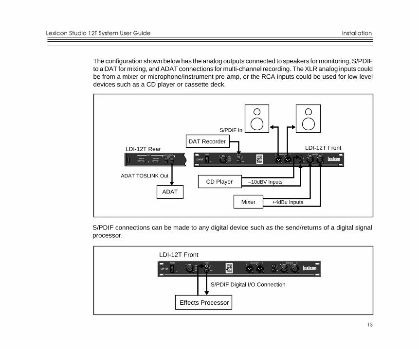
The configuration shown below has the analog outputs connected to speakers for monitoring, S/PDIFto a DAT for mixing, and ADAT connections for multi-channel recording. The XLR analog inputs couldbe from a mixer or microphone/instrument pre-amp, or the RCA inputs could be used for low-leveldevices such as a CD player or cassette deck.
S/PDIF connections can be made to any digital device such as the send/returns of a digital signalprocessor.
LDI-12T
L
R
In
Out
S/PDIF ANALOG OUT RL ANALOG IN RL
TIME
CODE
INPUT
POWER
PUSHPUSH PUSHPUSHPUSHPUSH
LDI-12T Front
Effects Processor
S/PDIF Digital I/O Connection
LDI-12T
L
R
In
Out
S/PDIF ANALOG OUT RL ANALOG IN RL
TIME
CODE
INPUT
POWER
PUSHPUSH PUSHPUSHPUSHPUSH
DAT RecorderLDI-12T Front
CD Player
Mixer
–10dBV Inputs
+4dBu Inputs
LDI-12T Rear
S/PDIF In
SYNC IN SYNC OUT OutIn
ADAT or S/PDIFADAT
AUDIO
ADAT TOSLINK Out
ADAT
Installation
14
14
Lexicon
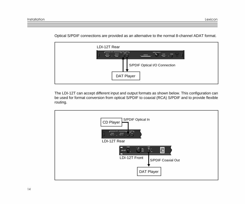
Optical S/PDIF connections are provided as an alternative to the normal 8-channel ADAT format.
The LDI-12T can accept different input and output formats as shown below. This configuration canbe used for format conversion from optical S/PDIF to coaxial (RCA) S/PDIF and to provide flexiblerouting.
SYNC IN SYNC OUT OutIn
ADAT or S/PDIFADAT
COMPUTERRS-422
AUDIO
POWER
WORD CLOCK IN
LDI-12T Rear
DAT Player
S/PDIF Optical I/O Connection
LDI-12T Rear
SYNC IN SYNC OUT OutIn
ADAT or S/PDIFADAT
AUDIO
S/PDIF Coaxial OutLDI-12T Front
LDI-12T
In
Out
S/PDIF
TIME
CODE
INPUT
POWER
PUSHPUSH
S/PDIF Optical InCD Player
DAT Player

15
15
Core-32 BasicsLexicon Studio 12T System User Guide
3Core-32 Basics
Signal RoutingUsing Cubase VST as an example of a host application, the following things determine signal routing.
1. LDI-12T connections.
2. Configuration of the Core-32 Control Panel.
3. Inputs and outputs selected and enabled in Cubase Audio VST.
Typically, all connections will appear directly in the application as available inputs and outputs alongwith the Core-32 Control Panel routing for the PC-90 and Punch Record. Details on these are coveredin the following section.
Core-32 Basics
16
16
Lexicon
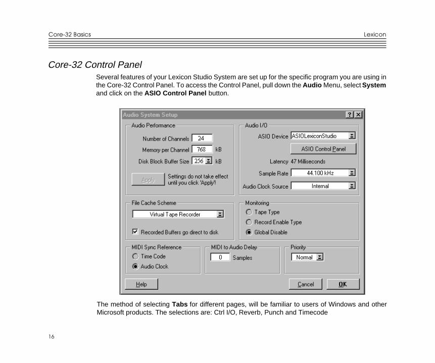
Core-32 Control PanelSeveral features of your Lexicon Studio System are set up for the specific program you are using inthe Core-32 Control Panel. To access the Control Panel, pull down the Audio Menu, select Systemand click on the ASIO Control Panel button.
The method of selecting Tabs for different pages, will be familiar to users of Windows and otherMicrosoft products. The selections are: Ctrl I/O, Reverb, Punch and Timecode
17
17
Core-32 BasicsLexicon Studio 12T System User Guide
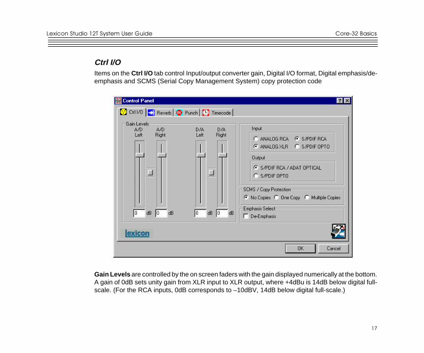
Ctrl I/OItems on the Ctrl I/O tab control Input/output converter gain, Digital I/O format, Digital emphasis/de-emphasis and SCMS (Serial Copy Management System) copy protection code
Gain Levels are controlled by the on screen faders with the gain displayed numerically at the bottom.A gain of 0dB sets unity gain from XLR input to XLR output, where +4dBu is 14dB below digital full-scale. (For the RCA inputs, 0dB corresponds to –10dBV, 14dB below digital full-scale.)
Core-32 Basics
18
18
Lexicon
Clicking the button between fader pairs links them as a stereo pair for convenient identical gain setting.Control clicking on the Link button will link the fader heads to one another while maintaining theirrelative levels. Clicking with the mouse on the fader head while holding down the ctrl key on thecomputer keyboard will set the selected fader or stereo grouped fader to 0dB. Gain levels can alsobe entered numerically by double-clicking on a numeric field, then entering a value.
Input/Output controls allow you to select S/PDIF or ADAT as the digital format for the optical inputand output connections, and to select between XLR or RCA connectors for the analog inputs.Conversion between Optical and Coaxial (RCA) S/PDIF is possible by selecting Optical input andCoaxial output, or the reverse. When Optical S/PDIF output is chosen, the RCA output remains active,creating a digital Y-cord or signal splitter. (NOTE: this is not true of the inputs —both S/PDIF inputscannot be used at the same time.)
Emphasis Select enables de-emphasis to be applied to the analog output. This function applies onlyto the analog converter, and does not affect signals from the S/PDIF or ADAT interface.
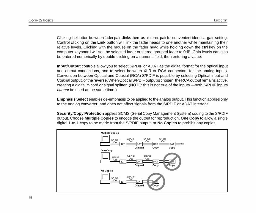
Security/Copy Protection applies SCMS (Serial Copy Management System) coding to the S/PDIFoutput. Choose Multiple Copies to encode the output for reproduction, One Copy to allow a singledigital 1-to-1 copy to be made from the S/PDIF output, or No Copies to prohibit any copies.
12T DAT
Original
Multiple Copies
One Copy
DAT
Copy
DAT
Copy
S/PDIFOut
S/PDIFOut
S/PDIFOut
S/PDIFOut
etc.
12T DAT
Original
DAT
Copy
DAT
Copy
S/PDIFOut
S/PDIFOut
S/PDIFOut
No Copies
12T DAT
Original
DAT
Copy
S/PDIFOut
S/PDIFOut
19
19
Core-32 BasicsLexicon Studio 12T System User Guide
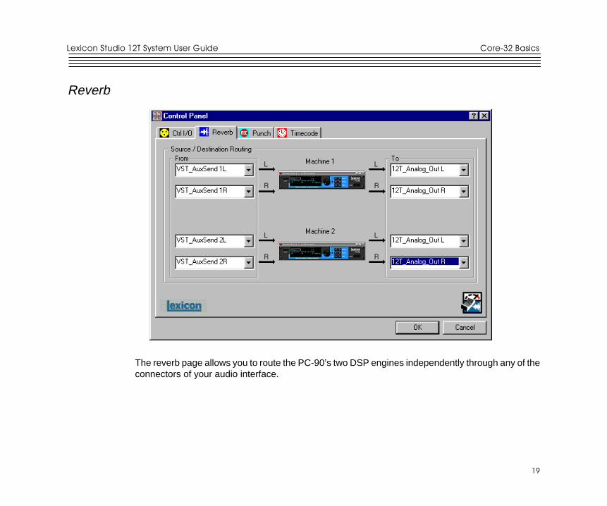
Reverb
The reverb page allows you to route the PC-90’s two DSP engines independently through any of theconnectors of your audio interface.
Core-32 Basics
20
20
Lexicon
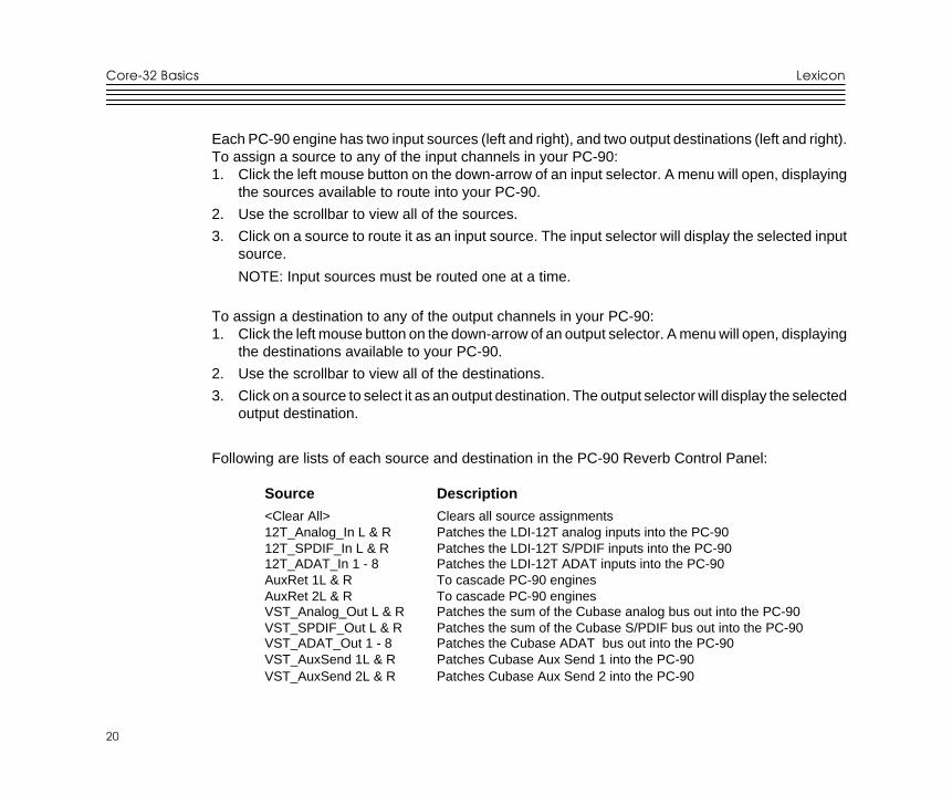
Each PC-90 engine has two input sources (left and right), and two output destinations (left and right).To assign a source to any of the input channels in your PC-90:1. Click the left mouse button on the down-arrow of an input selector. A menu will open, displaying
the sources available to route into your PC-90.
2. Use the scrollbar to view all of the sources.
3. Click on a source to route it as an input source. The input selector will display the selected inputsource.
NOTE: Input sources must be routed one at a time.
To assign a destination to any of the output channels in your PC-90:1. Click the left mouse button on the down-arrow of an output selector. A menu will open, displaying
the destinations available to your PC-90.
2. Use the scrollbar to view all of the destinations.
3. Click on a source to select it as an output destination. The output selector will display the selectedoutput destination.
Following are lists of each source and destination in the PC-90 Reverb Control Panel:
Source Description
<Clear All> Clears all source assignments12T_Analog_In L & R Patches the LDI-12T analog inputs into the PC-9012T_SPDIF_In L & R Patches the LDI-12T S/PDIF inputs into the PC-9012T_ADAT_In 1 - 8 Patches the LDI-12T ADAT inputs into the PC-90AuxRet 1L & R To cascade PC-90 enginesAuxRet 2L & R To cascade PC-90 enginesVST_Analog_Out L & R Patches the sum of the Cubase analog bus out into the PC-90VST_SPDIF_Out L & R Patches the sum of the Cubase S/PDIF bus out into the PC-90VST_ADAT_Out 1 - 8 Patches the Cubase ADAT bus out into the PC-90VST_AuxSend 1L & R Patches Cubase Aux Send 1 into the PC-90VST_AuxSend 2L & R Patches Cubase Aux Send 2 into the PC-90
21
21
Core-32 BasicsLexicon Studio 12T System User Guide
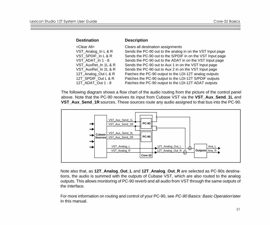
Destination Description
<Clear All> Clears all destination assignmentsVST_Analog_In L & R Sends the PC-90 out to the analog in on the VST Input pageVST_SPDIF_In L & R Sends the PC-90 out to the S/PDIF in on the VST Input pageVST_ADAT_In 1 - 8 Sends the PC-90 out to the ADAT in on the VST Input pageVST_AuxRet_In 1L & R Sends the PC-90 out to Aux 1 in on the VST Input pageVST_AuxRet_In 2L & R Sends the PC-90 out to Aux 2 in on the VST Input page12T_Analog_Out L & R Patches the PC-90 output to the LDI-12T analog outputs12T_SPDIF_Out L & R Patches the PC-90 output to the LDI-12T S/PDIF outputs12T_ADAT_Out 1 - 8 Patches the PC-90 output to the LDI-12T ADAT outputs
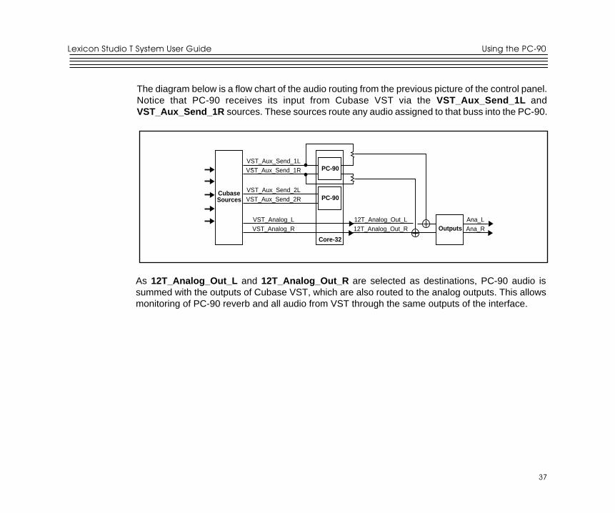
The following diagram shows a flow chart of the audio routing from the picture of the control panelabove. Note that the PC-90 receives its input from Cubase VST via the VST_Aux_Send_1L andVST_Aux_Send_1R sources. These sources route any audio assigned to that bus into the PC-90.
Note also that, as 12T_Analog_Out_L and 12T_Analog_Out_R are selected as PC-90s destina-tions, the audio is summed with the outputs of Cubase VST, which are also routed to the analogoutputs. This allows monitoring of PC-90 reverb and all audio from VST through the same outputs ofthe interface.
For more information on routing and control of your PC-90, see PC-90 Basics: Basic Operation laterin this manual.
CubaseSources
Core-32
VST_Aux_Send_1LVST_Aux_Send_1R
VST_Aux_Send_2LVST_Aux_Send_2R
VST_Analog_LVST_Analog_R
12T_Analog_Out_L12T_Analog_Out_R
Ana_LAna_R
PC-90
PC-90
Outputs
Core-32 Basics
22
22
Lexicon
Punch RecordThis page lets you select Input sources for Punch or overdub recording and Output monitor selectionsfor the sources selected for Punch or overdub recording. The Punch feature lets you perform overdubor punch recording by directly connecting to a Lexicon Studio interface — No external mixer isrequired.
The Windows 95 operating system has a delay when applications use host processing. (You canobserve the latency of your particular computer configuration on the System Setup page in Cubase.)This means that, when playing along with previously recorded tracks, the track you are playing willsound delayed while you are performing. This delay can be overcome by using an external mixer, orby using the Punch feature.
The punch feature mixes the input signals directly with the outputs selected for your monitor system(speakers or headphones) to avoid the inherent processing delay from the card to the computerapplication and back.
Unlike monitoring through a tape deck the input signal is monitored all the time. (With tape, the inputis typically monitored when the transport is in Stop or Record and muted during Play.)
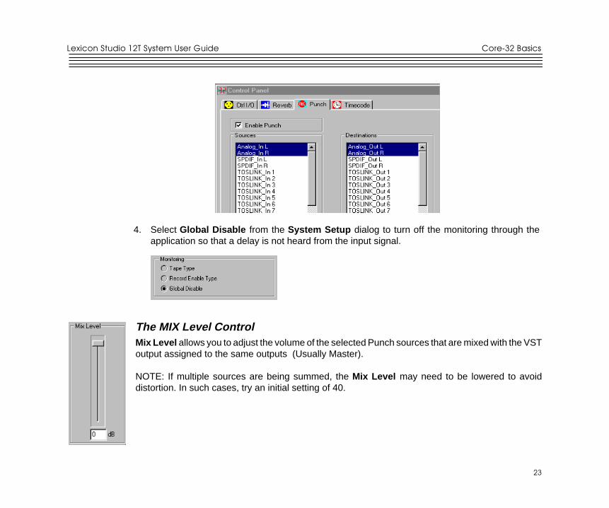
Configuring the Punch feature1. Select Enable Punch to turn on monitoring.
2. Select as many input sources as you like, using the shift or Ctrl key and mouse for multipleselections.
3. Select the outputs you are using for monitoring. (Often the analog left and right outputs will beconnected to an amp and speakers — digital connection to a mixer is, of course, also possible.)A mono mix of the selected inputs will be sent to the outputs.
23
23
Core-32 BasicsLexicon Studio 12T System User Guide
The MIX Level ControlMix Level allows you to adjust the volume of the selected Punch sources that are mixed with the VSToutput assigned to the same outputs (Usually Master).
NOTE: If multiple sources are being summed, the Mix Level may need to be lowered to avoiddistortion. In such cases, try an initial setting of 40.
4. Select Global Disable from the System Setup dialog to turn off the monitoring through theapplication so that a delay is not heard from the input signal.
Core-32 Basics
24
24
Lexicon
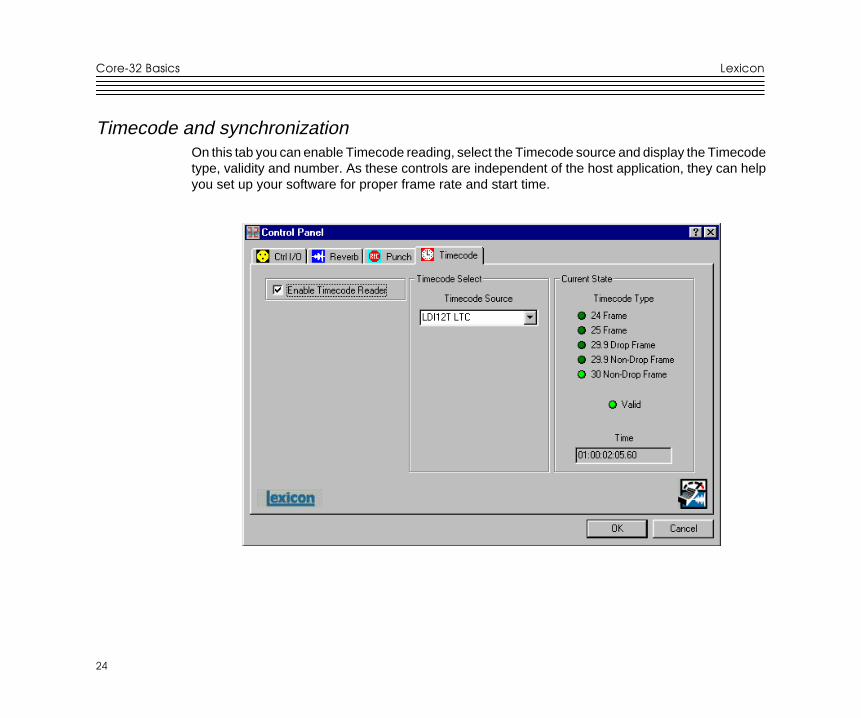
Timecode and synchronizationOn this tab you can enable Timecode reading, select the Timecode source and display the Timecodetype, validity and number. As these controls are independent of the host application, they can helpyou set up your software for proper frame rate and start time.
25
25
Core-32 BasicsLexicon Studio 12T System User Guide
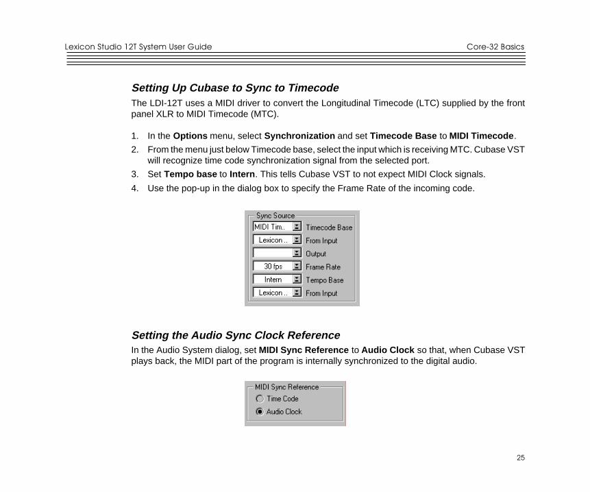
Setting Up Cubase to Sync to TimecodeThe LDI-12T uses a MIDI driver to convert the Longitudinal Timecode (LTC) supplied by the frontpanel XLR to MIDI Timecode (MTC).
1. In the Options menu, select Synchronization and set Timecode Base to MIDI Timecode .
2. From the menu just below Timecode base, select the input which is receiving MTC. Cubase VSTwill recognize time code synchronization signal from the selected port.
3. Set Tempo base to Intern . This tells Cubase VST to not expect MIDI Clock signals.
4. Use the pop-up in the dialog box to specify the Frame Rate of the incoming code.
Setting the Audio Sync Clock ReferenceIn the Audio System dialog, set MIDI Sync Reference to Audio Clock so that, when Cubase VSTplays back, the MIDI part of the program is internally synchronized to the digital audio.
Core-32 Basics
26
26
Lexicon
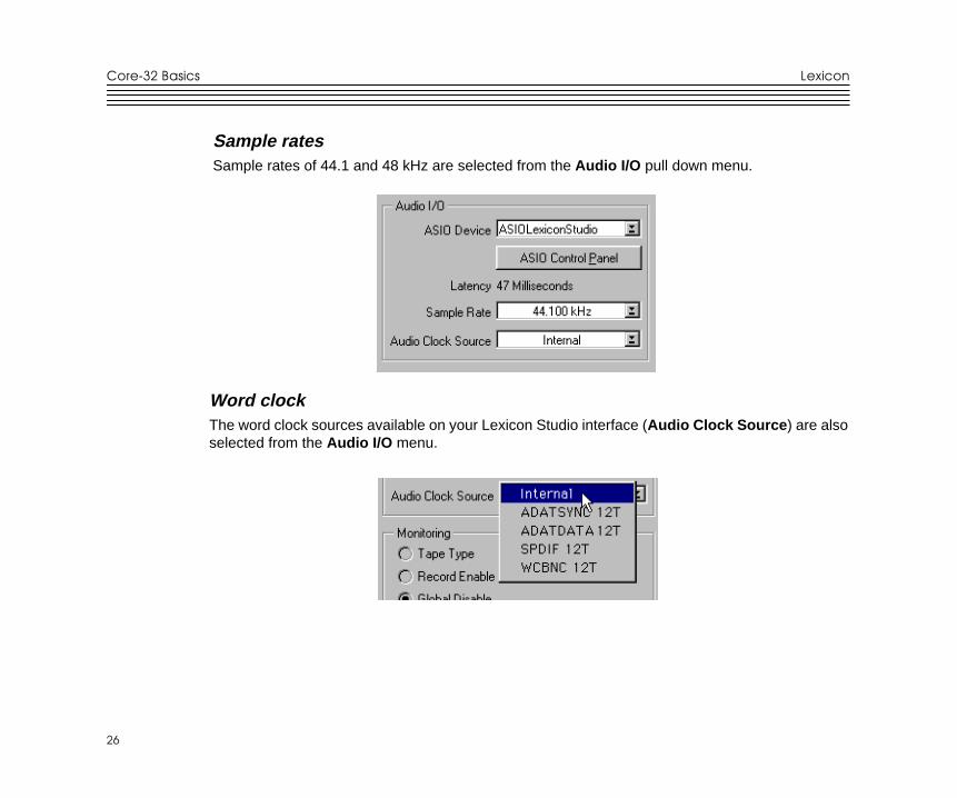
Sample ratesSample rates of 44.1 and 48 kHz are selected from the Audio I/O pull down menu.
Word clockThe word clock sources available on your Lexicon Studio interface (Audio Clock Source ) are alsoselected from the Audio I/O menu.
27
27
Core-32 BasicsLexicon Studio 12T System User Guide
Word Clock SourcesINTERNAL Selects the word clock generated by Cubase as the system master.
ADATSYNC 12T Selects the word clock provided on the ADAT Sync connector as the systemclock.
ADATDATA 12T Selects the word clock provided on the ADAT optical data connector as thesystem clock.
SPDIF 12T Selects the word clock provided by the S/PDIF signal (RCA or optical) as thesystem clock.
WCBNC 12T Selects the word clock provided on the Word Clock BNC connector as thesystem clock. This connector provides 75 ohm termination to the Word Clockchain.
RecordingGenerally, the system is locked to the incoming word clock source. For example, if you weretransferring 8 tracks from an ADAT, you would select the ADAT data as the word clock source. Thesame would be true for an S/PDIF source. With analog input , the internal setting is used, as thereis no incoming clock.
In larger systems with a digital mixer (such as Yamaha O2R or O3D), it is convenient to use the wordclock output and connect it to the BNC word clock input on the LDI-12T, selecting WCBNC 12T asthe word clock source. This provides centralized clocking of the connected units.

Core-32 Basics
28
28
Lexicon
29
29
Using the PC-90Lexicon Studio T System User Guide
4Using the PC-90
Basic OperationThe PC-90 combines the quality and power of Lexicon reverb on dedicated hardware with the easeand elegance of a software plug-in interface. Unlike software-based plug-ins, PC-90 providesoutstanding sonic quality with no burden on the system performance of your computer’s processor.
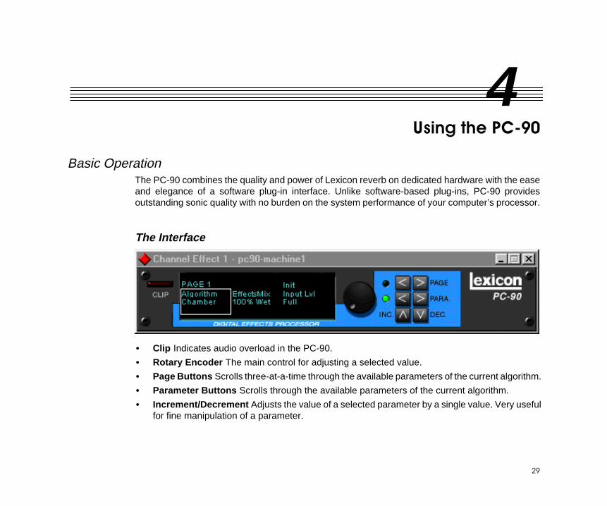
The Interface
• Clip Indicates audio overload in the PC-90.
• Rotary Encoder The main control for adjusting a selected value.
• Page Buttons Scrolls three-at-a-time through the available parameters of the current algorithm.
• Parameter Buttons Scrolls through the available parameters of the current algorithm.
• Increment/Decrement Adjusts the value of a selected parameter by a single value. Very usefulfor fine manipulation of a parameter.
Using the PC-90
30
30
Lexicon
Inserting a Plug-inThe interface for the PC-90 is available as a plug-in. Plug-ins are accessed differently in differentsoftware applications. To open a PC-90 plug-in in Cubase VST, you need to follow these steps:
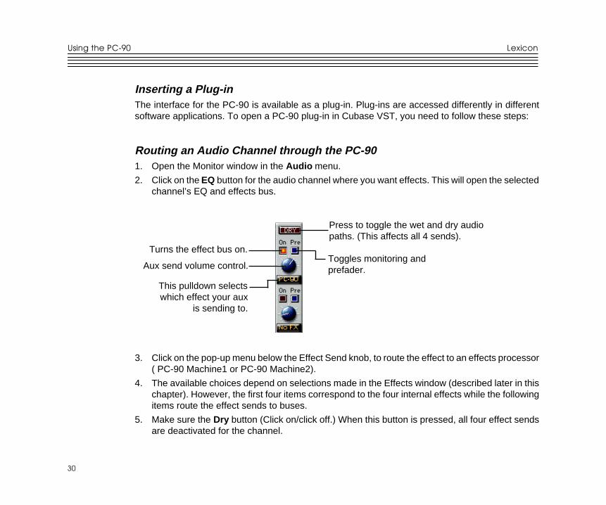
Routing an Audio Channel through the PC-901. Open the Monitor window in the Audio menu.
2. Click on the EQ button for the audio channel where you want effects. This will open the selectedchannel’s EQ and effects bus.
Aux send volume control.
Press to toggle the wet and dry audiopaths. (This affects all 4 sends).
Toggles monitoring andprefader.
Turns the effect bus on.
This pulldown selectswhich effect your aux
is sending to.
3. Click on the pop-up menu below the Effect Send knob, to route the effect to an effects processor( PC-90 Machine1 or PC-90 Machine2).
4. The available choices depend on selections made in the Effects window (described later in thischapter). However, the first four items correspond to the four internal effects while the followingitems route the effect sends to buses.
5. Make sure the Dry button (Click on/click off.) When this button is pressed, all four effect sendsare deactivated for the channel.
31
31
Using the PC-90Lexicon Studio T System User Guide
6. Click On for each effect send you want to activate and turn the corresponding Send Level knobto a moderate value.
7. If you want the signal to be sent to the effects before the faders, click on the Pre button for thesend.
8. With Pre-fader effect sends, the amount of effect for the channel is not affected by the volumefader. With Post-fader effect sends (Pre button not pressed), the amount of effect is proportionalto the channel volume, and will change with the volume fader movements.
The next step is to select programs and set the parameters for the effect processors. Since you willprobably need to adjust the send levels while doing this, leave the EQ window open.
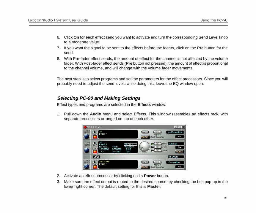
Selecting PC-90 and Making SettingsEffect types and programs are selected in the Effects window:
1. Pull down the Audio menu and select Effects. This window resembles an effects rack, withseparate processors arranged on top of each other.
2. Activate an effect processor by clicking on its Power button.
3. Make sure the effect output is routed to the desired source, by checking the bus pop-up in thelower right corner. The default setting for this is Master .
Using the PC-90
32
32
Lexicon
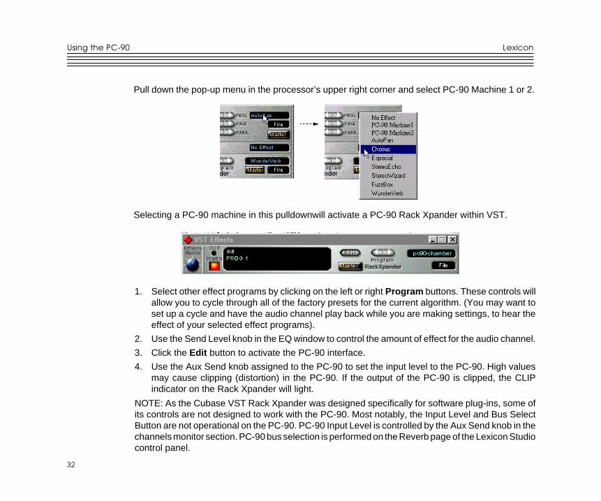
Pull down the pop-up menu in the processor’s upper right corner and select PC-90 Machine 1 or 2.
Selecting a PC-90 machine in this pulldownwill activate a PC-90 Rack Xpander within VST.
1. Select other effect programs by clicking on the left or right Program buttons. These controls willallow you to cycle through all of the factory presets for the current algorithm. (You may want toset up a cycle and have the audio channel play back while you are making settings, to hear theeffect of your selected effect programs).
2. Use the Send Level knob in the EQ window to control the amount of effect for the audio channel.
3. Click the Edit button to activate the PC-90 interface.
4. Use the Aux Send knob assigned to the PC-90 to set the input level to the PC-90. High valuesmay cause clipping (distortion) in the PC-90. If the output of the PC-90 is clipped, the CLIPindicator on the Rack Xpander will light.
NOTE: As the Cubase VST Rack Xpander was designed specifically for software plug-ins, some ofits controls are not designed to work with the PC-90. Most notably, the Input Level and Bus SelectButton are not operational on the PC-90. PC-90 Input Level is controlled by the Aux Send knob in thechannels monitor section. PC-90 bus selection is performed on the Reverb page of the Lexicon Studiocontrol panel.
33
33
Using the PC-90Lexicon Studio T System User Guide
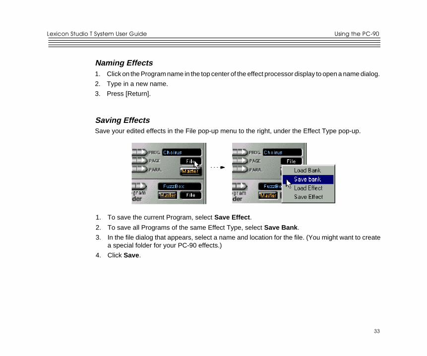
Naming Effects1. Click on the Program name in the top center of the effect processor display to open a name dialog.
2. Type in a new name.
3. Press [Return].
Saving EffectsSave your edited effects in the File pop-up menu to the right, under the Effect Type pop-up.
1. To save the current Program, select Save Effect .
2. To save all Programs of the same Effect Type, select Save Bank .
3. In the file dialog that appears, select a name and location for the file. (You might want to createa special folder for your PC-90 effects.)
4. Click Save.
Using the PC-90
34
34
Lexicon
Loading EffectsLoad effects from disk into the PC-90 as follows:1. Pull down the File menu.
2. To load a single Program, select Load Effect .
3. To load a complete Program Bank, select Load Bank .
4. In the file dialog that appears, find and click on the file you want to load.
The Effect settings are saved with your Song. If you want to use your edited effects in other Songs,you can save and load them separately.
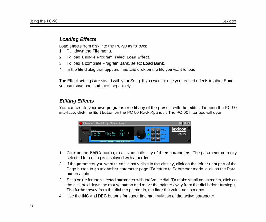
Editing EffectsYou can create your own programs or edit any of the presets with the editor. To open the PC-90interface, click the Edit button on the PC-90 Rack Xpander. The PC-90 Interface will open.
1. Click on the PARA button, to activate a display of three parameters. The parameter currentlyselected for editing is displayed with a border.
2. If the parameter you want to edit is not visible in the display, click on the left or right part of thePage button to go to another parameter page. To return to Parameter mode, click on the Para.button again.
3. Set a value for the selected parameter with the Value dial. To make small adjustments, click onthe dial, hold down the mouse button and move the pointer away from the dial before turning it.The further away from the dial the pointer is, the finer the value adjustments.
4. Use the INC and DEC buttons for super fine manipulation of the active parameter.
35
35
Using the PC-90Lexicon Studio T System User Guide
Beyond the Basics
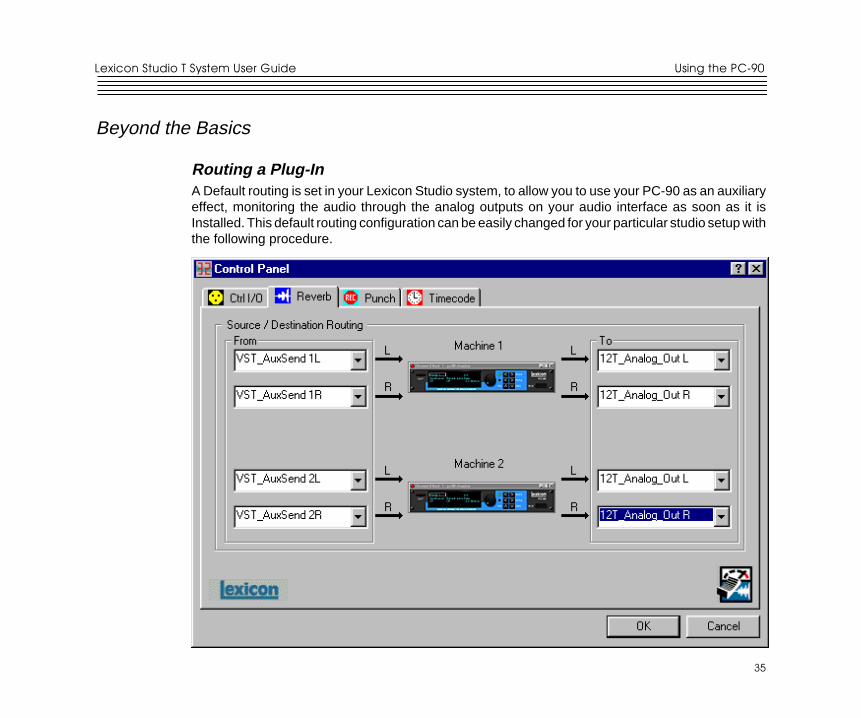
Routing a Plug-InA Default routing is set in your Lexicon Studio system, to allow you to use your PC-90 as an auxiliaryeffect, monitoring the audio through the analog outputs on your audio interface as soon as it isInstalled. This default routing configuration can be easily changed for your particular studio setup withthe following procedure.
Using the PC-90
36
36
Lexicon
The Reverb page on the Core-32 Control Panel allows you to route the two PC-90 DSP engines independentlythrough any of the connectors of your audio interface.
For each PC-90 engine, there are two input sources (left and right), and two output destinations (left and right). Toassign a source to any of the input channels in your PC-90:
1. Clicking the left mouse button on the down-arrow of an input selector will open a menu displaying all sourcesavailable to route into your PC-90.
2. Use the scrollbar to view the available sources.3. Click on a source to route it as an input source. The input selector will display your selection as the input source.
NOTE: Input sources can only be be routed one at a time.
To assign a destination to any of the output channels in your PC-90:
1. Click the left mouse button on the down-arrow of an output selector to open a menu of available destinations.2. Use the scrollbar to view the available destinations.3. Click on a source to route it as an output destination. The output selector will display your selection as the input
source.
37
37
Using the PC-90Lexicon Studio T System User Guide
The diagram below is a flow chart of the audio routing from the previous picture of the control panel.Notice that PC-90 receives its input from Cubase VST via the VST_Aux_Send_1L andVST_Aux_Send_1R sources. These sources route any audio assigned to that buss into the PC-90.
As 12T_Analog_Out_L and 12T_Analog_Out_R are selected as destinations, PC-90 audio issummed with the outputs of Cubase VST, which are also routed to the analog outputs. This allowsmonitoring of PC-90 reverb and all audio from VST through the same outputs of the interface.
CubaseSources
Core-32
VST_Aux_Send_1LVST_Aux_Send_1R
VST_Aux_Send_2LVST_Aux_Send_2R
VST_Analog_LVST_Analog_R
12T_Analog_Out_L12T_Analog_Out_R
Ana_LAna_R
PC-90
PC-90
Outputs
Using the PC-90
38
38
Lexicon
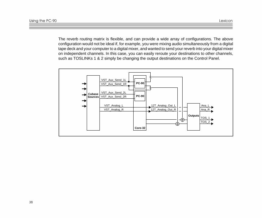
The reverb routing matrix is flexible, and can provide a wide array of configurations. The aboveconfiguration would not be ideal if, for example, you were mixing audio simultaneously from a digitaltape deck and your computer to a digital mixer, and wanted to send your reverb into your digital mixeron independent channels. In this case, you can easily reroute your destinations to other channels,such as TOSLINKs 1 & 2 simply be changing the output destinations on the Control Panel.
CubaseSources
Core-32
VST_Aux_Send_1LVST_Aux_Send_1R
VST_Aux_Send_2LVST_Aux_Send_2R
VST_Analog_LVST_Analog_R
12T_Analog_Out_L12T_Analog_Out_R
Ana_LAna_R
TOS_1TOS_2
PC-90
PC-90
Outputs

39
39
Using the PC-90Lexicon Studio T System User Guide
Automating the PC-90The PC-90 Digital Reverberator can be completely automated within any control software thatsupports automation. Refer to the user guide for your particular software package for support offeredfor this functionality. The following section describes PC-90 automation within Cubase VST.
To write enable the channel that PC-90 is assigned to, open the Cubase VST Mixer window and clickthe Write button.
Changes made to PC-90 parameters will be recorded to an Audio Mix Part. Any changes (even thosemade while the transport is in Stop) are recorded, as long as the Write button is enabled.
If you check the Arrange window after you stop playback, you will note that a special Mixer Track calledAudiomix has been created. This Track contains one long Part named Audiomix, in which all yourMonitor mixer actions are stored. Don’t worry about the length of this Part — it will automatically belengthened if you record past its end.
Please note that there is only one Audiomix Part/Track, created the first time you use the Writefunction in your Arrangement. No new Parts are created the next time you use the Write function —information is added to the existing Part.
To stop writing automation events, click the Write button a second time, or close the Mixer window.All changes to this track and its plug-ins will cease to record.
Using the PC-90
40
40
Lexicon
To playback automation in your mix:
1. Check that the Audiomix Track or Part are not muted.
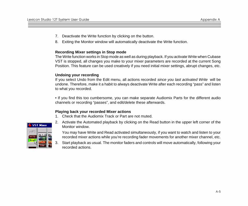
2. Activate Automated playback by clicking on the Read button in the upper left corner of the Monitorwindow.
If you want to watch and listen to your recorded mixer actions while you’re recording fader movementsfor another mixer channel, etc., you can activate Read and Write simultaneously.
Begin playback as usual. The monitor faders and controls will move automatically, following yourrecorded actions. You will also hear your plug-in automation events playing back with your audio.
41
41
ReferenceLexicon Studio 12T System User Guide
5Reference
PC-90 Algorithms
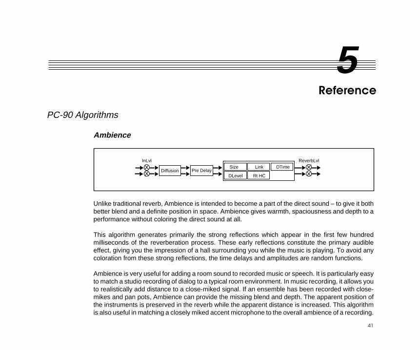
Ambience
Unlike traditional reverb, Ambience is intended to become a part of the direct sound – to give it bothbetter blend and a definite position in space. Ambience gives warmth, spaciousness and depth to aperformance without coloring the direct sound at all.
This algorithm generates primarily the strong reflections which appear in the first few hundredmilliseconds of the reverberation process. These early reflections constitute the primary audibleeffect, giving you the impression of a hall surrounding you while the music is playing. To avoid anycoloration from these strong reflections, the time delays and amplitudes are random functions.
Ambience is very useful for adding a room sound to recorded music or speech. It is particularly easyto match a studio recording of dialog to a typical room environment. In music recording, it allows youto realistically add distance to a close-miked signal. If an ensemble has been recorded with close-mikes and pan pots, Ambience can provide the missing blend and depth. The apparent position ofthe instruments is preserved in the reverb while the apparent distance is increased. This algorithmis also useful in matching a closely miked accent microphone to the overall ambience of a recording.
InLvl ReverbLvlDTimeSize
DLevel Rt HC
LinkPre DelayDiffusion
Reference
42
42
Lexicon
This allows a soloist to be increased in level without changing the apparent distance. Ambience canbe used in a recording situation any time a close-miked sound is undesirable.
When using Ambience in a mix, it is best to use a stereo send to the PC-90, carefully matching thepanning of the various close-miked sources to their positions in the mix. Leave the Mix control at 100%wet. the apparent distance of each source can be controlled by the level of its feed.
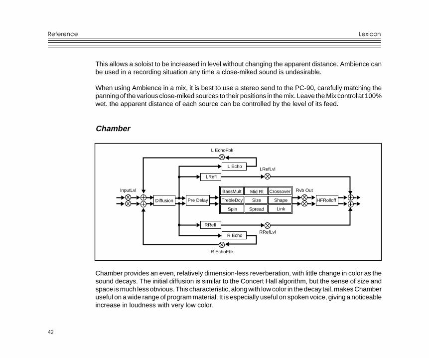
Chamber
L Echo
L EchoFbk
R EchoFbk
LRefl
Diffusion
InputLvl Rvb Out
LRefLvl
RRefLvl
Crossover
Shape
Link
TrebleDcy
Spin Spread
SizePre Delay HFRolloff
Mid RtBassMult
RRefl
R Echo
Chamber provides an even, relatively dimension-less reverberation, with little change in color as thesound decays. The initial diffusion is similar to the Concert Hall algorithm, but the sense of size andspace is much less obvious. This characteristic, along with low color in the decay tail, makes Chamberuseful on a wide range of program material. It is especially useful on spoken voice, giving a noticeableincrease in loudness with very low color.
43
43
ReferenceLexicon Studio 12T System User Guide
Concert Hall
InLvl ReverbLvlCrossover
Spread
Chorus
Size
Spin Link
Rt Hc
Def
Depth
Diffusion
ShapePre Delay
Mid RtBassMult
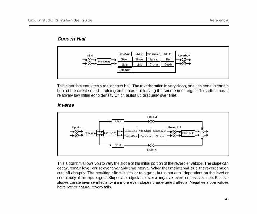
This algorithm emulates a real concert hall. The reverberation is very clean, and designed to remainbehind the direct sound – adding ambience, but leaving the source unchanged. This effect has arelatively low initial echo density which builds up gradually over time.
Inverse
HFRolloff
LRefl
Diffusion
InputLvl
LRefLvl
ReverbLvl
RRefLvl
Pre DelayCrossover
ShapeTrebleDcy Duration
Mid SlopeLowSlope
RRefl
This algorithm allows you to vary the slope of the initial portion of the reverb envelope. The slope candecay, remain level, or rise over a variable time interval. When the time interval is up, the reverberationcuts off abruptly. The resulting effect is similar to a gate, but is not at all dependent on the level orcomplexity of the input signal. Slopes are adjustable over a negative, even, or positive slope. Positiveslopes create inverse effects, while more even slopes create gated effects. Negative slope valueshave rather natural reverb tails.
Reference
44
44
Lexicon
Room
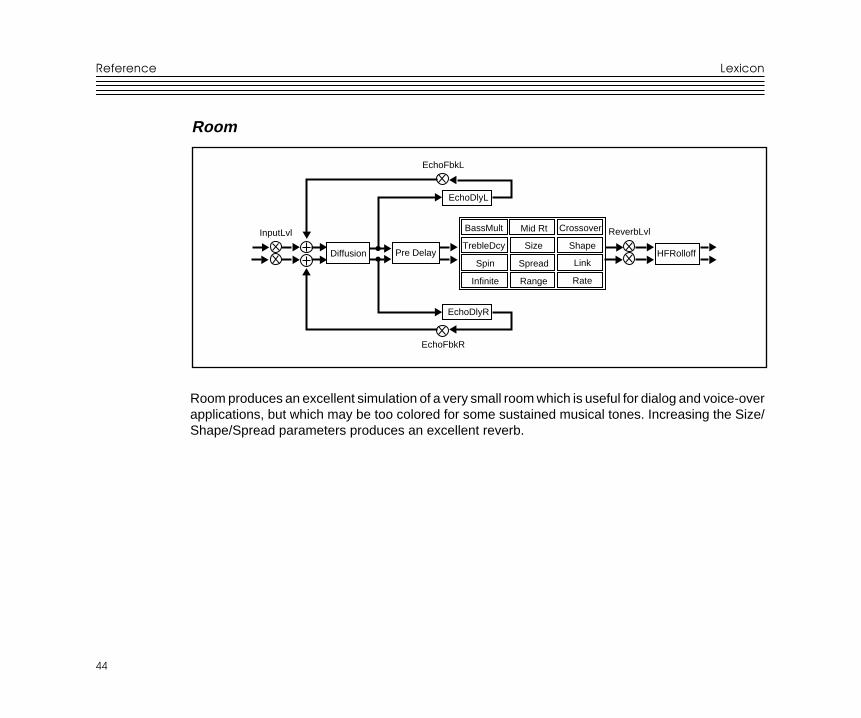
Room produces an excellent simulation of a very small room which is useful for dialog and voice-overapplications, but which may be too colored for some sustained musical tones. Increasing the Size/Shape/Spread parameters produces an excellent reverb.
EchoDlyL
EchoFbkL
EchoFbkR
Diffusion
InputLvl Crossover
Shape
Link
TrebleDcy
Spin Spread
RateInfinite Range
SizePre Delay
Mid RtBassMult
EchoDlyR
HFRolloff
ReverbLvl
45
45
ReferenceLexicon Studio 12T System User Guide
The ParametersThe PC-90 has a wide range of parameters to control the sound of your algorithms. Not all parametersare found in all algorithms.
ChorusIn the Concert Hall algorithm, Chorus randomizes delay times and introduces modulation to makereverberation sound less metallic. Increasing Chorus increases the rate of modulation. BecauseChorusing can cause pitch variation, this parameter should be set with care when using sources withvery little pitch wobble (such as guitar or piano). A good practice is to increase the setting until the pitchwobble becomes noticeable, then lower it slightly.
CrossoverCrossover sets the frequency at which the transition from Mid Rt to Low Rt takes place. This controlshould be set at least two octaves higher than the low frequency you want to boost. For example, toboost a signal at 100Hz, set Crossover to 400Hz. (This setting works well for classical music).Crossover works best around 400Hz for boosting low frequencies, and around 1.5 kHz for cutting lowfrequencies.
DecayIn Ambience, Decay controls the length of the ambience “tail”.
Decay LevelIn Ambience, Decay Level controls the level of the ambience “tail”. When Decay Level is off, ambienceconsists entirely of the early reflection signal.
DefinitionIn the Concert Hall algorithm, Definition affects the echo density buildup rate during the latter part ofthe decay period. When set to Off, the rate is determined by the program material. Raising Definitionthrough its range (1-99%) causes the sound to become choppier - the decrease in echo densitycreates increasingly distinct, repetitive echo trails.
Reference
46
46
Lexicon
DepthIn the Concert Hall algorithm, Depth sets the output amplitude envelope, changing the listener’sperspective from the front to the rear of the hall.
DiffusionA Diffusion control is provided in all algorithms. It controls the degree to which initial echo densityincreases over time. High settings of Diffusion result in initial build-up of echo density, and low settingscause low initial build-up. Echo density is also affected by Size; smaller spaces will sound denser. Toenhance percussion, use high settings of Diffusion. For clearer, more natural vocals, mixes, and pianomusic, use low or moderate settings of Diffusion. Note that, at some extreme input levels, high settingsof Diffusion may trigger the overload indicators on the Clip display.
DurationIn the Inverse algorithm, Duration determines the length of time, in milliseconds, which passes beforethe cutoff in Inverse effects.
Echo DelaysEcho Delay L and Echo Delay R provide echoes to the left and right channels. Unlike Delay andReflect, which are isolated right and left delays, left and right echoes are blended in the diffusor. Theechoes are routed both to the outputs and through a feedback path.
Echo FeedbackFbk L and Fbk R modify the levels of the echo feedback path. The range is from -100% to 0 to +100%.
Effects MixMix controls the ratio of dry and wet signal present at the PC-90 outputs. When the PC-90 is used asan effects loop, this control should always be set for 100% wet.
HF RolloffHF Rolloff sets the high frequency cutoff of a low-pass filter. This parameter affects both channels.
47
47
ReferenceLexicon Studio 12T System User Guide
InfiniteIn the Room algorithm, this control is provided to turn the Infinite effect On or Off.
Input LvlInLvl controls the level of the unprocessed (dry) signal into the effect.
LinkWhen Link is set to On, the reverb time (Mid RT) and Spread scale linearly as the Size control is varies.For some special effects, Mid RT, Spread and Size can be unlinked.
Mid Rt and Bass MultMid Rt sets the reverb time for mid-frequency signals. Because low frequency reverb time (Low Rt)is a multiplier of Mid Rt, Mid Rt acts as a master control for the reverb time. Bass Mult sets the reverbtime for low-frequency signals, as a multiplier of the Mid Rt parameter. For example, if Bass Mult isset to 2X, and Mid Rt is set to two seconds, the low frequency reverb time will be four seconds. Fora naturally sounding hall ambience, we recommend values of 1.5X or less.
Pre DelayPre Delay adjusts an additional time delay between the input of signal and the onset of reverberation.This control is not intended to mimic the time delays in natural spaces. In real rooms, the build-up ofreverberation is gradual, and the initial time gap is usually relatively short. Natural spaces are bestemulated by adjusting Spread for the desired effective predelay.
Range and RateIn the Room algorithm, these controls are used to reduce coloration for small room sizes or to reducethe sense of periodicity when the Infinite control is on. These controls allow you to set the range ofa moving delay and the speed at which it moves. High settings of either control may be unsuitable forsustained tones, like piano.
Reference
48
48
Lexicon
Reverb LevelReverb Level sets the amount of reverberation in the processed signal. It is normally FULL, but maybe reduced for effects where the pre-echoes should dominate.
Reflect DelaysIn the Chamber and Inverse algorithms, L Refl and R Refl provide pre-echoes to the left and rightchannels. In Chamber, the maximum delay value is 1.2 seconds. In Inverse, the maximum delay valueis 800 milliseconds.
Reflect LevelsL RefLvl and R RefLvl control the level of the reflections (L Refl and R Refl). The range of each levelis from Full (0dB) to -85dB, and to Off.
Shape, SpreadShape and Spread work together to control the overall ambience of the reverberation. Shapedetermines the contour of the reverberation envelope. With Shape all the way down, reverberationbuilds explosively, and decays quickly. As Shape is advanced, reverberation builds up more slowlyand sustains for the time set by the Spread. With Shape in the middle, the build-up and sustain of thereverberation envelope emulates a large concert hall (assuming that Spread is at least halfway up,and that Size is 30 meters or larger). Low Spread settings result in a rapid onset of reverberation atthe beginning of the envelope, with little or no sustain. Higher settings spread out both the buildup andsustain.
SizeSize sets the rate of build-up of diffusion after the initial period (which is controlled by Diffusion). TheSize control changes a reverb sound from very large to very small. Generally, you should set thiscontrol to approximate the size of the acoustic space you are trying to create, before adjustinganything else. The size in meters is roughly equal to the longest dimension of the space. Audio istemporarily muted when Size is changed.
49
49
ReferenceLexicon Studio 12T System User Guide
SlopeIn the Inverse algorithm, Slope determines the shape of the reverb envelope. When set to 0, the levelof reverb remains unchanged over its duration, then cuts off abruptly (depending upon the amountof Diffusion in use). Setting Slope above 0 causes the level of reverb to rise smoothly from soft to louduntil the sound is cut off. The greater the slope, the softer the initial reverberation and the morepronounced its rise. With negative values, the reverb drops from its initial level to a quieter one beforecutoff. The lower the slope, the more pronounced the drop-off.
SpinSpin affects the movement of the reverberation tail. The object of Spin is to continuously alter thetimbre of the reverberant sound. This makes the result more natural, without making the position ofthe instruments unstable. Spin should typically be set to values between 10% and 50%. Higher valuesmay make the timbre of piano, guitar and other precisely pitched instruments unstable.
Treble DcyTreble Dcy sets the frequency above which a 6dB/octave low-pass filter attenuates the reverberatedsignal. It does not attenuate Reflection Delays. High frequencies are often rolled off with thisparameter, resulting in more natural-sounding reverberation. Setting a low frequency for thisparameter can actually shorten the reverb time, as it damps the audio as it recirculates.
Reference
50
50
Lexicon
Preset Descriptions
Notes on Preset DesignPC-90 incorporates the results of a great deal of research into acoustics and reverberation.Reverberation, or reflected sound energy, gives recorded music a sense of being performed in a realacoustic location.
Using the Size and Spread ParametersIn the PC-90, the Size and Spread controls allow adjustment of the buildup and decay of the initialpart of the reverberation envelope. In the Chamber algorithm, Size acts as a master control for theapparent size of the space being created by PC-90. Both Spread and Mid Rt vary linearly with thesetting of Size. Thus, maximum reverb time and spread may require high settings of Size. To find anappropriate reverb sound, start with a preset with a similar sound to what you want to end up with.Simply varying Size is often sufficient to arrive at the exact sound you are seeking.
Once a size has been selected, Spread and Shape are used to adjust the shape and duration of theinitial reverb envelope, which together provide the major sonic impression of room size. The densityis set by the size control, and the rate of decay is set by Mid Rt.
As Shape is raised to about 1/8 of its range, the initial sharp attack of the reverberation is reduced,and reverberation builds more slowly. The envelope then sustains briefly before it begins to die awayat the rate set by Mid Rt. Spread has little or no effect on this shape.
When Shape is at 1/4 of its range, buildup is even slower and the sustain is longer. Now Spread affectsthe length of both the buildup and sustain. As a rough estimate, the sustain will be approximately thetime value indicated by the Spread display (in milliseconds).
51
51
ReferenceLexicon Studio 12T System User Guide
As Shape is raised further, the buildup and sustain remain similar, but now a secondary sustainappears in the envelope, at a lower level than the first. This secondary plateau simulates a verydiffused reflection off the back wall of a hall, and is effective in creating a sense of size and space.This reflection becomes stronger and stronger, reaching an optimal loudness when Shape is at about1/2 of its range.
The highest Shape settings are typically used for effects. Near the top of the scale the back wallreflection becomes stronger than the earlier part of the envelope, resulting in an inverse sound.
NOTE: None of these effects are audible unless Mid Rt is set short enough. Generally, Mid Rt shouldbe set to a value of about 1.2 seconds for small rooms, and up to 2.4 seconds or so for “halls”. Sizeshould also be set to a value appropriate to the desired hall size (note, however, that small sizes colorthe reverberation). 15 meters makes a very small room, and 38 meters is useful for a large hall.
Used with care, Shape and Spread allow PC-90 to produce superior ambience – a sound which isspacious and has great depth – without the long reverberation of a church.
Random Delay ElementsPC-90 incorporates random delay elements in its reverb. These elements have several effects. First,there is a reduction of long-lived modes in the reverberant decay, which makes the decay less metallicand reduces the apparent reverb time. The random elements also improve the steady-state timbreof the effect.
The speed at which the delay elements move is controlled by Spin. Settings higher than about 40-40% can cause audible pitch wobble in very critical material such as classical guitar or piano and canalso cause noise on pure tones. This noise is not audible in speech, however, and, for mixed musicor speech, values up to 48% can give an improved sound.
Creating a Realistic SoundWhen you set out to create a sound, the first and most important decision is how big a space you want.The best way to start is to listen to several presets and choose the one which sounds closest to whatyou have in mind. If necessary, use Size to make a slightly larger or smaller sound, as needed.
Reference
52
52
Lexicon
Next use Mid Rt to fine-tune the amount of time the reverberation takes to die away at the end ofmusical phrases. Actual halls vary a great deal in their Mid Rt values. The setting of Bass Mult is alsocritical in matching the sound of an existing hall. An ideal concert hall would have a Bass Mult settingof 1.2. It is rare when actual physical spaces exceed 1.5. many (if not most) good recordingenvironments have values of 1.0 or less, so a value of 0.8 could be tried when attempting to matchan existing hall.
Spread also adjusts the effective reverb time when the music is running. Higher values of Spreadproduce a longer effective reverb time, which, in turn, gives greater spaciousness to the sound.
1
A-1
Appendix ALexicon Studio 12T System User Guide
Appendix AThird Party Support
This section provides user notes and excerpts from user guides from supported third partyapplications. Documented below are several important features for Steinberg Cubase VST, such asautomation.
Steinberg Cubase VST
AutomationVolume and Pan Automation – Dynamic Events or Monitor MixerCubase VST offers two ways of automating volume and pan: the Dynamic Events set in the AudioEditor and the Write function in the Monitor Mixer. The two methods have their specific properties anduses, as described below:
Dynamic EventsThe Dynamic events allow you to control the volume and panning individually for each segment. Thisallows you to create fade-ins, fade-outs and auto-pan effects, which are then integral parts of eachsegment. This is all done in the Audio Editor.
What this means is that if you for example create a volume curve for one segment, and later copy thissegment for use in other places in the song, all copies will “inherit” the volume curve of the originalsegment. You can later adjust the curve for each individual segment, if needed.
A more advanced possibility is to use Ghost events. These are audio events which all share asegment, and thereby share a volume or pan curve. This means that if one is adjusted, they are allaffected.
If you use the Dynamic Events to control volume, you cannot go above unity gain (0.0 dB).
Appendix A
2
A-2
Lexicon
Monitor Mixer AutomationUsing the Write function in the Monitor mixer you can automate Volume and Panning (actually allmixer settings and changes) for each audio channel. All Tracks in the Arrange window that are setto play back via this audio channel will be affected likewise by these controls. This method is describedon the following pages.
Let’s say, as an example, that one channel is first used for a guitar and later in the song for vocals.If you then use the Monitor window to lower the volume in the guitar intro, you will get the same lowervolume for the vocal, since they are on the same channel.
When you are using the Monitor mixer to control volume, you can go above unity gain (actually amplifythe sound). Furthermore, you can automate Mutes and Solos.
ConclusionSo, when to use Dynamic Events and when to use the Monitor Mixer depends on what is needed atthe moment; if you need to make minute adjustment of shorter segments and repeat those in the Song,you should choose Dynamic Events. If you make longer non-repeating recordings and prefer to adjustvolumes via (on-screen) faders, you use the Monitor window.
Do not hesitate to combine the two methods of automation, simultaneously or during different partsof the Song. The settings you make in the Monitor window are relative to the volume value deliveredby the Dynamic Events automation. For example, if the Dynamic Event volume has a value of -2.0dB, and you set the Monitor window fader to -0.4 dB, the resulting volume will be -2.4 dB. l
Please note that the Monitor Mixer automation is not restricted to Volume and Pan - Mutes, Solo, EQand Effect settings can also be automated, as with the Lexicon PC-90.
3
A-3
Appendix ALexicon Studio 12T System User Guide
Automating the Monitor mixerYour actions in the Monitor mixer window can be automated in a very straightforward way: by “writing”them into a special Audiomix Part. When played back, this Part will repeat your fader movements andbutton presses just like you performed them. You will even see the faders and buttons move on thescreen, like on a physical mixer with motorized controls.
What can be automated?Mixdown in Cubase VST can be completely automated! The following parameter settings arerecorded with the Write function:
For each channel:
• Volume
• Pan
• Mute
• Solo
• EQ On switch
• 4 x Effect Send Active switches
• 4 x Effect Send levels
• 4 x Effect Send PRE switches
• Effect DRY switch
• Settings for 4 EQ modules
Global for all channels
• Master volume Left and Right
• 4 x Master Effect Send levels
• 4 x Effect On/Off
• 4 x Effect Program selection
• 4 x Effect parameters (the 16 first parameters for each Effect “processor”)

Appendix A
4
A-4
Lexicon
• 4 x Master Effect On/Off
• 4 x Master Effect Program selection
• 4 x Master Effect parameters (the 8 first parameters for each Master Effect)
The PC-90 has been enabled for complete automation. As Steinberg Cubase VST providesautomation for only the first 16 parameters of a channel effect, and the first 8 parameters for a mastereffect. Lexicon has prioritized the PC-90 parameters to take the fullest advantage of this feature.
Recording your actions1. Open the Monitor window.
2. Click on the Write button in the upper left corner to activate recording.
While the Write button is “lit” (activated), every volume, pan, mute or solo movement you makewill be recorded.
3. Start playback.
4. Move the faders and pan controls, mute and solo as you would during a manual mixdown. As youcan repeat this recording several times, it is probably easiest to mix one or a couple of channelsat a time, and stop and deactivate the Write function in between. That way, you can also Undoyour last run if you’re not satisfied, using the Undo command on the Edit menu.
5. Stop playback.
6. If you check the Arrange window, you will note that a special Mixer Track called Audiomix hasbeen created. This Track contains one long Part named Audiomix, in which all your Monitor mixeractions are stored. Don’t worry about the length of this Part; it will automatically be lengthenedif you record past its end. Please note that there is only one Audiomix Part/Track, created the firsttime you use the Write function in your Arrangement. No new Parts are created the next time youuse the Write function; information is added to the existing Part instead.
5
A-5
Appendix ALexicon Studio 12T System User Guide
7. Deactivate the Write function by clicking on the button.
8. Exiting the Monitor window will automatically deactivate the Write function.
Recording Mixer settings in Stop modeThe Write function works in Stop mode as well as during playback. If you activate Write when CubaseVST is stopped, all changes you make to your mixer parameters are recorded at the current SongPosition. This feature can be used creatively if you need initial mixer settings, abrupt changes, etc.
Undoing your recordingIf you select Undo from the Edit menu, all actions recorded since you last activated Write will beundone. Therefore, make it a habit to always deactivate Write after each recording “pass” and listento what you recorded.
• If you find this too cumbersome, you can make separate Audiomix Parts for the different audiochannels or recording “passes”, and edit/delete these afterwards.
Playing back your recorded Mixer actions1. Check that the Audiomix Track or Part are not muted.
2. Activate the Automated playback by clicking on the Read button in the upper left corner of theMonitor window.
You may have Write and Read activated simultaneously, if you want to watch and listen to yourrecorded mixer actions while you’re recording fader movements for another mixer channel, etc.
3. Start playback as usual. The monitor faders and controls will move automatically, following yourrecorded actions.
Appendix A
6
A-6
Lexicon
Moving and Muting the Audiomix Part
The Audiomix Part can be handled as any Mixer Part:
• If you want to turn off Monitor mixer automation from the Arrange window, you can mute theAudiomix Part or Track.
• You can copy recorded mixer actions to several places in your Arrangement by cutting out therelevant section of the Audiomix Part with the Scissors tool and duplicating it, placing the copieswherever you want them.
Working with one Audiomix Part for each Audio ChannelAlthough Cubase VST only creates one dedicated Audiomix Track, there is a way to structure yourMixer Automation into different Parts for different channels, which makes it easier to edit and redomixer recordings you’re not satisfied with:
1. Record your fader movements and other mixer actions for the first audio channel, as describedon the previous page.
2. Deactivate the Write function and go to the Arrange window.
3. Make a new Mixer Track. It might be a good idea to name it after the audio channel you just mixed,to avoid confusion later on.
4. Move the entire Audiomix Part to the new Track.
5. Open the Monitor again, activate the Write function and record your mixer actions for the nextaudio channel. Now Cubase VST creates a new Audiomix Part on the original, empty AudiomixTrack. If you activate the Read function, your previously recorded Part will be played back fromits new Track, so you can watch your recorded fader movements while you continue with newaudio channels.
6. Repeat steps 2 to 5 for as many channels you like.
You will end up with a number of Mixer Tracks, all playing back simultaneously, affecting differentaudio channels in the Monitor mixer. If you want to, you can keep it that way. If you like to clean upyour Arrange window, you can Merge the Parts into one.
7
A-7
Appendix ALexicon Studio 12T System User Guide
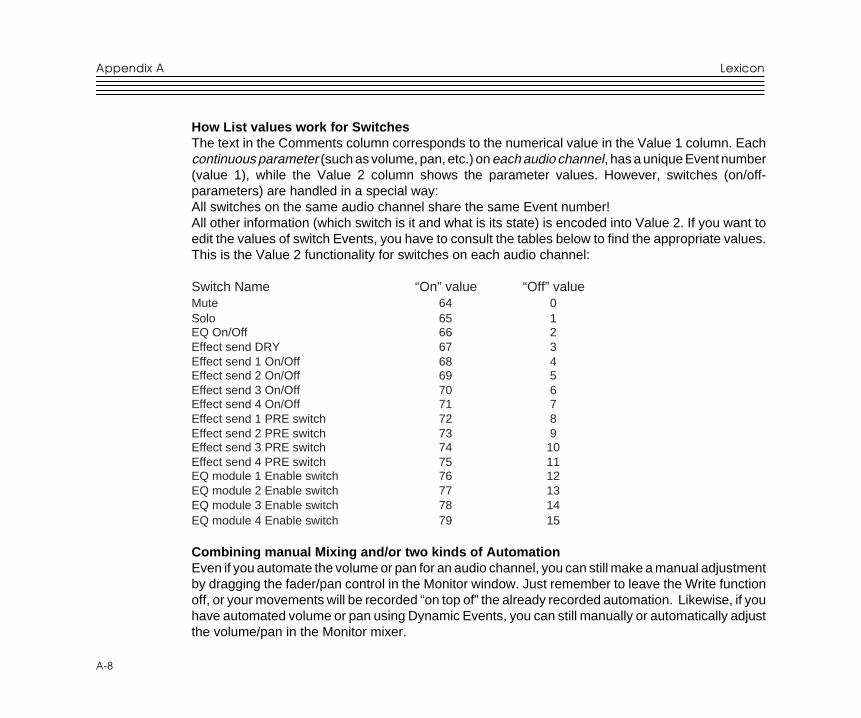
Editing the Audiomix PartThe Audiomix Part contains Mixer Events, which can be edited in List Edit:
1. Select the Audiomix Part in the Arrange Window.
2. Open List Edit.
3. Pull the divider to the right so that you can see the Comment column.
This column shows which Mixer parameter (volume, pan etc.) and audio channel each Eventcontrols.
Switch parameters (parameters with on/off values) are handled in a special way. All informationabout a switch Event (switch name, on/off) will be displayed in the Comments column, but do nottry to edit a Switch value if you are not sure about how the Value 2 encoding works.
4. Select an Event that corresponds to the fader (or other Mixer control) you want to edit.
5. Pull down the Mask pop-up menu and select “Mask It!”. This will hide all Events except those ofthe same type as the selected (that is, only Events of the same type and the same audio channelas the selected one will be shown).
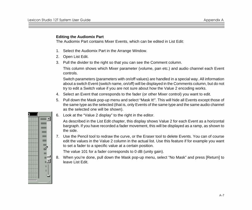
6. Look at the “Value 2 display” to the right in the editor.
As described in the List Edit chapter, this display shows Value 2 for each Event as a horizontalbargraph. If you have recorded a fader movement, this will be displayed as a ramp, as shown tothe side.
7. Use the Pencil tool to redraw the curve, or the Eraser tool to delete Events. You can of courseedit the values in the Value 2 column in the actual list. Use this feature if for example you wantto set a fader to a specific value at a certain position.
The value 101 for a fader corresponds to 0 dB (unity gain).
8. When you’re done, pull down the Mask pop-up menu, select “No Mask” and press [Return] toleave List Edit.
Appendix A
8
A-8
Lexicon
How List values work for SwitchesThe text in the Comments column corresponds to the numerical value in the Value 1 column. Eachcontinuous parameter (such as volume, pan, etc.) on each audio channel, has a unique Event number(value 1), while the Value 2 column shows the parameter values. However, switches (on/off-parameters) are handled in a special way:All switches on the same audio channel share the same Event number!All other information (which switch is it and what is its state) is encoded into Value 2. If you want toedit the values of switch Events, you have to consult the tables below to find the appropriate values.This is the Value 2 functionality for switches on each audio channel:
Switch Name “On” value “Off” valueMute 64 0Solo 65 1EQ On/Off 66 2Effect send DRY 67 3Effect send 1 On/Off 68 4Effect send 2 On/Off 69 5Effect send 3 On/Off 70 6Effect send 4 On/Off 71 7Effect send 1 PRE switch 72 8Effect send 2 PRE switch 73 9Effect send 3 PRE switch 74 10Effect send 4 PRE switch 75 11EQ module 1 Enable switch 76 12EQ module 2 Enable switch 77 13EQ module 3 Enable switch 78 14EQ module 4 Enable switch 79 15
Combining manual Mixing and/or two kinds of AutomationEven if you automate the volume or pan for an audio channel, you can still make a manual adjustmentby dragging the fader/pan control in the Monitor window. Just remember to leave the Write functionoff, or your movements will be recorded “on top of” the already recorded automation. Likewise, if youhave automated volume or pan using Dynamic Events, you can still manually or automatically adjustthe volume/pan in the Monitor mixer.
1
B-1
Appendix BLexicon Studio 12T System User Guide
Troubleshooting
Installation troubleshooting
Problems Starting AutodetectionIf there was a card installed in your system previous to this installation you should run uninstall toremove all the components that may be in your system. Uninstall will reset your system to the statethat it was in before the Core-32 card was installed. Make sure that all other devices are installed andworking properly. An existing conflict or device that is in a problem state (!) can cause problems wheninstalling additional cards.
Problems During AutodetectionIf the computer freezes when detecting new hardware it may be necessary to reset the computerhardware. To accomplish this, turn the computer off, wait three seconds, then turn the computer on.Pressing Ctrl+Alt+Delete or pressing the reset button will not reinitialize your computer hardware.
Manual DetectionIf auto detection does not work, you may have to use Manual detection by running Add New Hardwarefrom the Control Panel.
Resolving Hardware ConflictsWindows 95 may not be able to configure the Core-32 without creating conflicts with another device.This can happen as more devices are installed and system resources are depleted. Related errormessages that may appear are:• Turn off a device to make room for the new device
• Disable the new device
Appendix B
Appendix B
2
B-2
Lexicon
• Reconfigure a legacy device to make room for the new device
Use the Hardware Conflict Troubleshooter in Windows Help. The Troubleshooting Wizard walks youthrough step-by-step troubleshooting or will suggest solutions to fix the problem.
Tip: If you have a motherboard with five (5) PCI slots you may find that 2 of the slots share one IRQ.As sharing IRQs can be problematic on some devices, move the Core-32 to another slot. See yourmanufacturer’s manual for more information.
Problematic DevicesIf the Core-32 seems to configure properly but is in a problem state it will be marked with anexclamation point (!) in the Device manager. This indicates that Windows 95 tried to load a driver butfailed. Reinstall the Core-32 driver per the installation instructions.
SoftwareLED Status on Core 32There are 2 status LEDs mounted on the card. When the audio application is booted and the driversare loaded, one LED will light and the other will blink repeatedly.
PC Troubleshooting
Power Up ProblemsIf the computer will not power up after initially installing a Core-32, the Core-32 or another expansioncard may be partially dislodged from the expansion slot on the motherboard. Symptoms may includekeyboard lights on, power indicator lit, or the hard drive spinning. Remove the Core-32 and verify thatthe system boots without it installed. Verify that the expansion cards are seated securely in the slots.Remove all peripheral devices from the Core-32 including PC-90 and cables, checking for re-bootingeach time.
3
B-3
Appendix BLexicon Studio 12T System User Guide
VGA CardsScreen redraws may create pops, clicks or crashes. Many times, this can be either the bus beinglocked, or the CPU being interrupted too often to maintain a reliable stream of audio. Certain VGAcards appear to be the cause of this problem. To test for this, drag and drop one of your open windowswhile playing a multitrack session. Turn the VGA acceleration off and perform the same test. This maysolve the problem. Contact the VGA card manufacturer and obtain the most recent drivers for thatboard and report the problem.
Suggested Mother board BIOS setting suggestions.
• Disable Video BIOS/ROM shadow
• Disable Video BIOS/ROM cacheable
• Disable PCI/VGA palette snoop
• Enable PCI 2.1 Compliancy
TIP: Reporting problems to hardware manufacturersWhen reporting a problem to your hardware manufacturer, they will ask you if your motherboard bios,VGA card and other peripheral card drivers are up to date. It is a good idea to have this informationready when you first contact them.
AGP (Accelerated Graphics Port)Some PC motherboards can use an AGP graphics adapter. This standard was designed to take thegraphics operations off of the PCI bus and onto a dedicated bus — the AGP port. The AGP port isphysically and logically separate from the PCI bus. Using this port to handle graphics operations freesthe PCI bus for audio and SCSI data activity. Contact your computer manufacturer for moreinformation on the benefits of using an AGP port.
Appendix B
4
B-4
Lexicon
Optimizing Windows 95 for Audio ApplicationsFollowing are some suggestions that may improve your computers performance as a dedicatedDigital Audio Workstation. Some of these suggestions disable some Windows 95 optimizationfeatures and may slow the overall performance of your system when using non-audio applications.
Add MemoryAdding RAM to your computer will reduce the chance that Windows needs to use Virtual Memory.
Defragment Your Hard DrivesDefragment your drives on a regular basis.
Run Scan Disk RegularlyScan disk can detect and fix problems before becoming fatal.
Disconnect Any Mapped Drives That Are No Longer Connected To YourComputerDrives will appear in Explorer with a red “x” under them if the drive is no longer connected to yoursystem.
Verify no Drives are CompressedControlPanel/System/Performance: Make sure it says “Not Installed” after Disk Compression
Disable Write-Behind Disk CachingSets the number of kilobytes that Win95 reads ahead. By reading ahead the audio drive is workingharder than necessary.
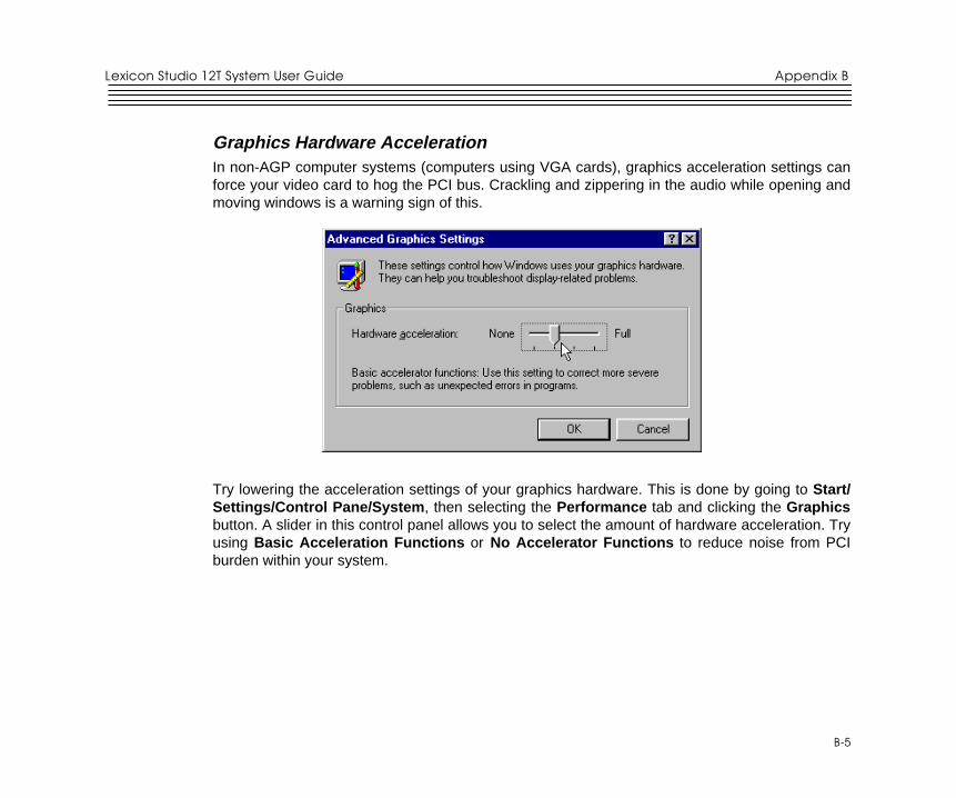
5
B-5
Appendix BLexicon Studio 12T System User Guide
Graphics Hardware AccelerationIn non-AGP computer systems (computers using VGA cards), graphics acceleration settings canforce your video card to hog the PCI bus. Crackling and zippering in the audio while opening andmoving windows is a warning sign of this.
Try lowering the acceleration settings of your graphics hardware. This is done by going to Start/Settings/Control Pane/System , then selecting the Performance tab and clicking the Graphicsbutton. A slider in this control panel allows you to select the amount of hardware acceleration. Tryusing Basic Acceleration Functions or No Accelerator Functions to reduce noise from PCIburden within your system.
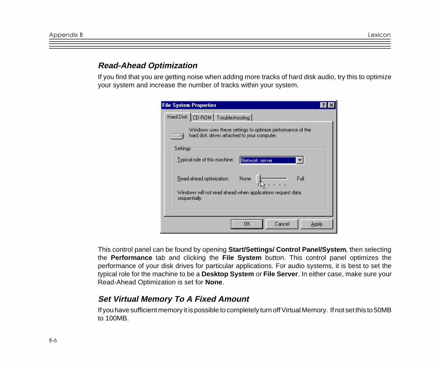
Appendix B
6
B-6
Lexicon
Read-Ahead OptimizationIf you find that you are getting noise when adding more tracks of hard disk audio, try this to optimizeyour system and increase the number of tracks within your system.
This control panel can be found by opening Start/Settings/ Control Panel/System , then selectingthe Performance tab and clicking the File System button. This control panel optimizes theperformance of your disk drives for particular applications. For audio systems, it is best to set thetypical role for the machine to be a Desktop System or File Server . In either case, make sure yourRead-Ahead Optimization is set for None .
Set Virtual Memory To A Fixed AmountIf you have sufficient memory it is possible to completely turn off Virtual Memory. If not set this to 50MBto 100MB.
7
B-7
Appendix BLexicon Studio 12T System User Guide
Common Problems and SolutionsThe Lexicon Studio Sound System is not recognized by Windows 95 when first installed.Make sure you have a Plug and Play ready BIOS that complies with V2.1 of the PCI specification.Load the default values of the BIOS and try installing the card again.
The Lexicon Studio Sound System appears in the Device Manager tagged with a yellowexclamation point.Windows tried to load a driver but failed. Reload the driver.
Check the resources page for a resource conflict. Resources in your computer may have beendepleted before the Core-32 card was installed. Try moving the board to another PCI slot or removea card to make more resources available.
A legacy device (a card with manually-set IRQs) may need to be disabled by removing the card.
The Lexicon Studio Sound System appears in the Device Manager with no resourcesassigned.Make sure you have a Plug and Play ready BIOS that complies with V2.1 of the PCI specification.Load the default values of the BIOS and try installing the card again.
Opening the Lexicon Studio ASIO Control Panel crashes the computer.This may indicate that you are running the first release of Windows 95. To determine the version ofWindows 95 you are running:1. In the Control Panel, double-click on System .
2. Click the General tab.
3. Locate the version number under the System heading and refer to the following table:
Version number Version of Windows 95
4.00.950 Windows 954.00.950A Windows 95 plus the Service Pack 1 Update, or OEM Service Release 1.4.00.950B OEM Service Release 2 (OSR2)
Upgrade to Windows 95 A or B if necessary.
Appendix B
8
B-8
Lexicon
Poor System PerformanceA computer with a fast CPU does not guarantee high performance. If your system is not performingas well as it should be, try some of these suggestions:• Quit any open applications other than your audio software.
• Use a fast IDE drive for your audio. Getting audio off the PCI bus creates more bandwidth for theLexicon Studio System. You might also try a fast SCSI drive with a PCI SCSI controller, whichwill yield performance almost as high as the IDE due to the faster speed of SCSI.
• Add memory. (Cubase VST recommends at least 64MB.)
Pops and clicksIf you have a PCI-based VGA board , screen redraws may create pops, clicks or crashes. Try turningVGA acceleration off. The Graphics accelerator slider is accessed by pressing the Graphics buttonin the Performance page of the System properties box. This may solve the problem.
Contact the VGA card manufacturer and obtain the most recent drivers for that board and to reportthe problem.
Minimize any unnecessary windows that are constantly redrawing
Use an AGP (Accelerated Graphics Port) video card if your motherboard supports this.
Verify that the SCSI card drivers are up to date.
Verify all audio and data cables are securely fastened to their respective connectors.
Try another Word clock source. Switch the word clock from internal to external or vice versa.
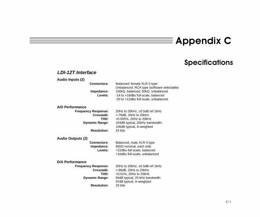
1
C-1
Appendix CLexicon Studio 12T System User Guide
Appendix C
SpecificationsLDI-12T InterfaceAudio Inputs (2)
Connectors: Balanced: female XLR-3 typeUnbalanced: RCA type (software selectable)
Impedance: 100kΩ, balanced; 50kΩ, unbalancedLevels: -14 to +18dBu full-scale, balanced
-20 to +12dBu full-scale, unbalanced
A/D PerformanceFrequency Response: 20Hz to 20kHz, ±0.5dB ref 1kHz
Crosstalk: <-76dB, 20Hz to 20kHzTHD: <0.005%, 20Hz to 20kHz
Dynamic Range: 104dB typical, 20kHz bandwidth;106dB typical, A-weighted
Resolution: 24 bits
Audio Outputs (2)Connectors: Balanced, male XLR-3 typeImpedance: 600Ω nominal, each side
Levels: +22dBu full-scale, balanced+16dBu full-scale, unbalanced
D/A PerformanceFrequency Response: 20Hz to 20kHz, ±0.5dB ref 1kHz
Crosstalk: <-86dB, 20Hz to 20kHzTHD: <0.01%, 20Hz to 20kHz
Dynamic Range: 94dB typical, 20 kHz bandwidth97dB typical, A-weighted
Resolution: 20 bits
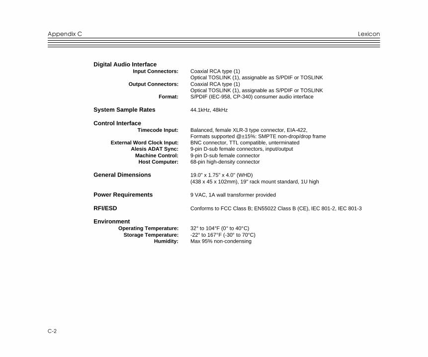
Appendix C
2
C-2
Lexicon
Digital Audio InterfaceInput Connectors: Coaxial RCA type (1)
Optical TOSLINK (1), assignable as S/PDIF or TOSLINKOutput Connectors: Coaxial RCA type (1)
Optical TOSLINK (1), assignable as S/PDIF or TOSLINKFormat: S/PDIF (IEC-958, CP-340) consumer audio interface
System Sample Rates 44.1kHz, 48kHz
Control InterfaceTimecode Input: Balanced, female XLR-3 type connector, EIA-422,
Formats supported @±15%: SMPTE non-drop/drop frameExternal Word Clock Input: BNC connector, TTL compatible, unterminated
Alesis ADAT Sync: 9-pin D-sub female connectors, input/outputMachine Control: 9-pin D-sub female connector
Host Computer: 68-pin high-density connector
General Dimensions 19.0" x 1.75" x 4.0" (WHD)(438 x 45 x 102mm), 19" rack mount standard, 1U high
Power Requirements 9 VAC, 1A wall transformer provided
RFI/ESD Conforms to FCC Class B; EN55022 Class B (CE), IEC 801-2, IEC 801-3
EnvironmentOperating Temperature: 32° to 104°F (0° to 40°C)
Storage Temperature: -22° to 167°F (-30° to 70°C)Humidity: Max 95% non-condensing
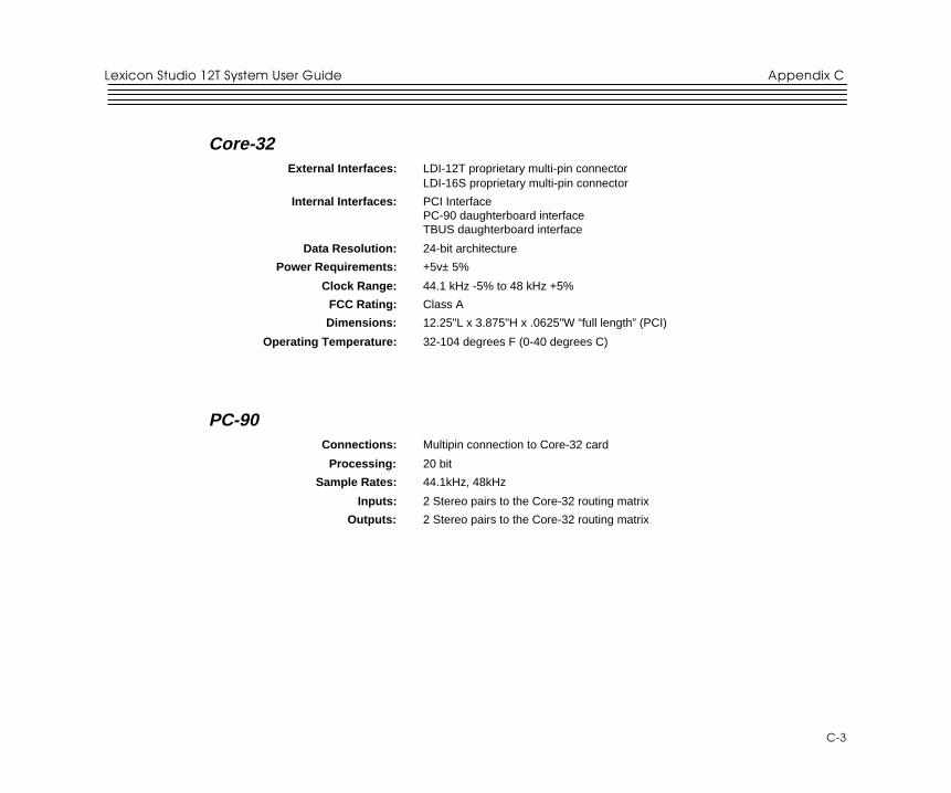
3
C-3
Appendix CLexicon Studio 12T System User Guide
Core-32External Interfaces: LDI-12T proprietary multi-pin connector
LDI-16S proprietary multi-pin connector
Internal Interfaces: PCI InterfacePC-90 daughterboard interfaceTBUS daughterboard interface
Data Resolution: 24-bit architecture
Power Requirements: +5v± 5%
Clock Range: 44.1 kHz -5% to 48 kHz +5%
FCC Rating: Class A
Dimensions: 12.25"L x 3.875"H x .0625"W “full length” (PCI)
Operating Temperature: 32-104 degrees F (0-40 degrees C)
PC-90Connections: Multipin connection to Core-32 card
Processing: 20 bit
Sample Rates: 44.1kHz, 48kHz
Inputs: 2 Stereo pairs to the Core-32 routing matrix
Outputs: 2 Stereo pairs to the Core-32 routing matrix
Appendix C
4
C-4
Lexicon