lgb11xx series gigabit managed enet switch · lgb11xx series gigabit managed enet switch...
TRANSCRIPT

LGB11XX SERIES
GIGABIT MANAGED ENET SWITCH
INSTALLATION AND GETTING STARTED GUIDE
24/7 TECHNICAL SUPPORT AT 1.877.877.2269 OR VISIT BLACKBOX.COM

2
NEED HELP?LEAVE THE TECH TO US
LIVE 24/7TECHNICALSUPPORT1.877.877.2269
1.877.877.2269 BLACKBOX.COM
TABLE OF CONTENTS
SAFETY INFORMATION ............................................................................................................................................................................... 4
RELATED PUBLICATIONS ............................................................................................................................................................................ 5
REVISION HISTORY ..................................................................................................................................................................................... 6
1. SPECIFICATIONS ...................................................................................................................................................................................... 7
2. OVERVIEW ............................................................................................................................................................................................... 112.1 Description ..........................................................................................................................................................................................................112.2 Switch Architecture ...........................................................................................................................................................................................112.3 Network Management Options .........................................................................................................................................................................112.4 Hardware Description ....................................................................................................................................................................................... 12 2.4.1 1000BASE-T Ports ........................................................................................................................................................................................................12 2.4.2 SFP Transceiver Slots ..................................................................................................................................................................................................12 2.4.3 Port and System Status LEDs ....................................................................................................................................................................................123. NETWORK PLANNING ........................................................................................................................................................................... 133.1 Introduction to Switching ................................................................................................................................................................................. 133.2 Application Examples ....................................................................................................................................................................................... 134. INSTALLING THE SWITCH .................................................................................................................................................................... 144.1 Selecting a Site .................................................................................................................................................................................................. 144.2 Ethernet Cabling ................................................................................................................................................................................................ 144.3 Equipment Checklist ......................................................................................................................................................................................... 144.4 Package Contents ............................................................................................................................................................................................. 154.5 Mounting ............................................................................................................................................................................................................ 15 4.5.1 Rackmounting................................................................................................................................................................................................................16 4.5.2 Desktop or Shelf Mounting .........................................................................................................................................................................................164.6 Installing an Optional SFP Transceiver ........................................................................................................................................................... 174.7 Connecting to a Power Source ......................................................................................................................................................................... 174.8 Connecting to the Console Port ....................................................................................................................................................................... 184.9 Wiring Map for Serial Cable .............................................................................................................................................................................. 184.10 Operation of Web-based Management ......................................................................................................................................................... 195. MAKING NETWORK CONNECTIONS .................................................................................................................................................... 205.1 Connecting Network Devices ........................................................................................................................................................................... 205.2 Twisted-Pair Connections ................................................................................................................................................................................ 205.3 Cabling Guidelines ............................................................................................................................................................................................ 205.4 Connecting to PCs, Servers, Hubs, and Switches .......................................................................................................................................... 205.5 Network Wiring Connections ........................................................................................................................................................................... 215.6 Fiber Optic SFP Devices ................................................................................................................................................................................... 225.7 Connectivity Rules............................................................................................................................................................................................. 225.8 1000BASE-T Cable Requirements ................................................................................................................................................................... 225.9 1000- Mbps Gigabit Ethernet Collision Domain ............................................................................................................................................. 225.10 100-Mbps Fast Ethernet Collision Domain ................................................................................................................................................... 23
3
NEED HELP?LEAVE THE TECH TO US
LIVE 24/7TECHNICALSUPPORT1.877.877.2269
1.877.877.2269 BLACKBOX.COM
TABLE OF CONTENTS
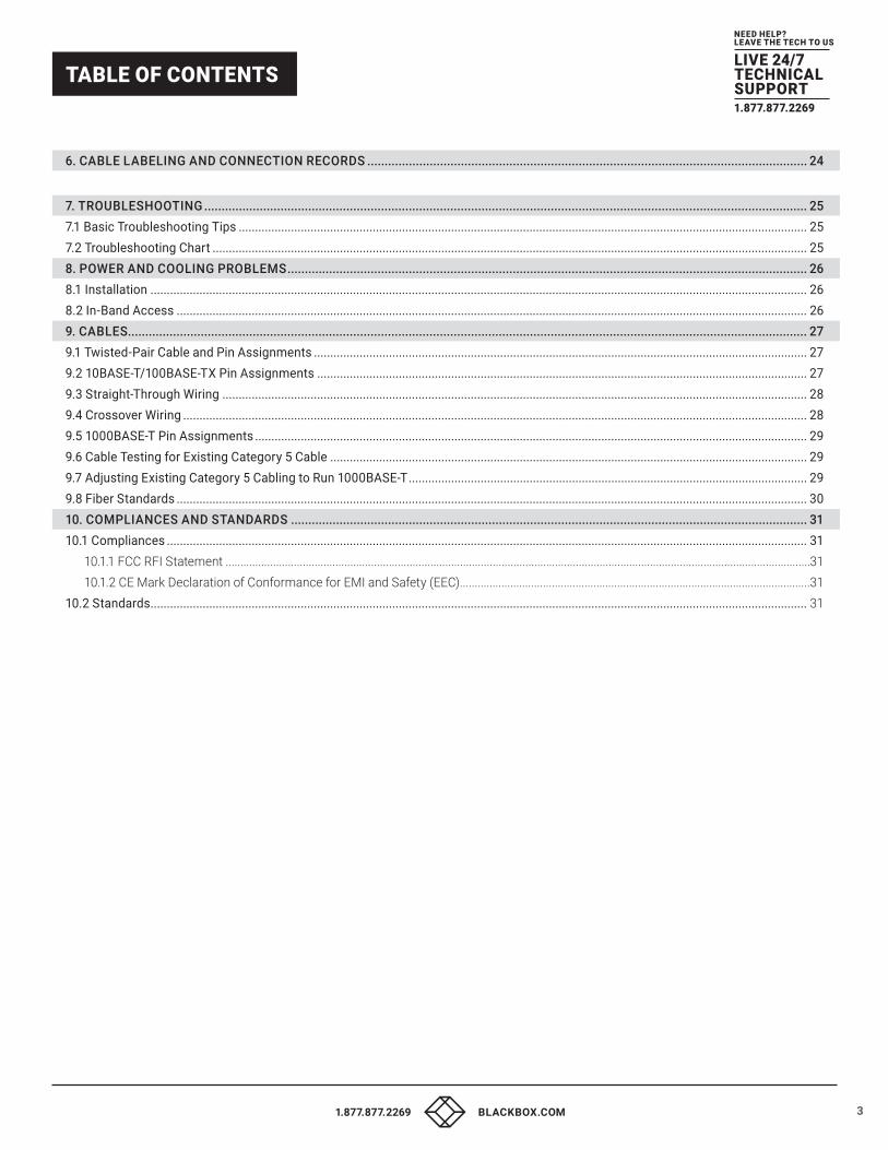
6. CABLE LABELING AND CONNECTION RECORDS ............................................................................................................................... 24
7. TROUBLESHOOTING .............................................................................................................................................................................. 257.1 Basic Troubleshooting Tips .............................................................................................................................................................................. 257.2 Troubleshooting Chart ...................................................................................................................................................................................... 258. POWER AND COOLING PROBLEMS ...................................................................................................................................................... 268.1 Installation ......................................................................................................................................................................................................... 268.2 In-Band Access ................................................................................................................................................................................................. 269. CABLES .................................................................................................................................................................................................... 279.1 Twisted-Pair Cable and Pin Assignments ....................................................................................................................................................... 279.2 10BASE-T/100BASE-TX Pin Assignments ...................................................................................................................................................... 279.3 Straight-Through Wiring ................................................................................................................................................................................... 289.4 Crossover Wiring ............................................................................................................................................................................................... 289.5 1000BASE-T Pin Assignments ......................................................................................................................................................................... 299.6 Cable Testing for Existing Category 5 Cable .................................................................................................................................................. 299.7 Adjusting Existing Category 5 Cabling to Run 1000BASE-T .......................................................................................................................... 299.8 Fiber Standards ................................................................................................................................................................................................. 3010. COMPLIANCES AND STANDARDS ..................................................................................................................................................... 3110.1 Compliances .................................................................................................................................................................................................... 31 10.1.1 FCC RFI Statement .....................................................................................................................................................................................................31 10.1.2 CE Mark Declaration of Conformance for EMI and Safety (EEC) ......................................................................................................................3110.2 Standards ......................................................................................................................................................................................................... 31

4
NEED HELP?LEAVE THE TECH TO US
LIVE 24/7TECHNICALSUPPORT1.877.877.2269
1.877.877.2269 BLACKBOX.COM
SAFETY INFORMATION
SAFETY INFORMATION
CAUTION: CIRCUIT DEVICES ARE SENSITIVE TO STATIC ELECTRICITY, WHICH CAN DAMAGE THEIR DELICATE ELECTRONICS. DRY WEATHER CONDITIONS OR WALKING ACROSS A CARPETED FLOOR MAY CAUSE YOU TO ACQUIRE A STATIC ELECTRICAL CHARGE.
TO PROTECT YOUR DEVICE, ALWAYS:
�� Touch the metal chassis of your computer to ground the static electrical charge before you pick up the circuit device.
�� Pick up the device by holding it on the left and right edges only.
NOTE: The switch is for indoor use only.
�� Self-demolition of the switch is strictly prohibited. Damage caused by self-demolition will void the warranty.
�� Do not place the switch outdoors or in a sandstorm.
�� Before installation, make sure the input power supply and product specifications are compatible with each other.
�� To reduce the risk of electric shock, disconnect all AC or DC power cords and cables to completely remove power from the unit.
�� Before importing / exporting configuration, please make sure the firmware version is always the same.
�� After firmware upgrade, the switch will replace the configuration automatically with the latest firmware version.

5
NEED HELP?LEAVE THE TECH TO US
LIVE 24/7TECHNICALSUPPORT1.877.877.2269
1.877.877.2269 BLACKBOX.COM
RELATED PUBLICATIONS
RELATED PUBLICATIONS The User’s Manual and the Management Guide give specific information on how to operate and use the management functions of the switch:
To download from the Web site:
1. Go to www.blackbox.com
2. Enter the part number (LGB1110A, LGB1126A-R2, or LGB1152A) in the search box.
3. Click on the product in the “Product Results” page.
4. Click on the “Support” tab on the product page,
and select the document you wish to download.
If you have any trouble accessing the Black Box site to download the manual, you can contact our Technical Support at 877-877-2269 or [email protected].

6
NEED HELP?LEAVE THE TECH TO US
LIVE 24/7TECHNICALSUPPORT1.877.877.2269
1.877.877.2269 BLACKBOX.COM
REVISION HISTORY
REVISION HISTORY Release Number: 6.38
Date: 10/19/2015
Revision: A1

7
NEED HELP?LEAVE THE TECH TO US
LIVE 24/7TECHNICALSUPPORT1.877.877.2269
1.877.877.2269 BLACKBOX.COM
CHAPTER 1: SPECIFICATIONS
TABLE 1-1. SPECIFICATIONS
SWITCH PART NUMBER LGB1110A LGB1126A-R2 LGB1152A
CONNECTORS
Total Ports 10 26 52
RJ-45 (10M/100M/1G) 8 24 48
Uplinks (100M/1G) (2) RJ-45/SFP combo (2) RJ-45/SFP combo (4) SFP
Console (1) RJ-45 (1) RJ-45 (1) RJ-45
HARDWARE PERFORMANCE
Forwarding Capacity 14.88 Mpps 38.68 Mpps 77.38 Mpps
Switching Capacity 20 Gbps 52 Gbps 104 Gbps
Mac Table 8K 8K 32K
Jumbo Frames 9216 Bytes 9216 Bytes 14000 Bytes
ENVIRONMENTAL
Operating Temperature 32 to 104° F (0 to 40 °C) 32 to 104° F (0 to 40 °C) 32 to 104° F (0 to 40 °C)
Storage Temperature -4 to +158 F ( -20 to +70° C) -4 to +158 F ( -20 to +70° C) -4 to +158 F ( -20 to +70° C)
Altitude <1000 ft. (<3000 m) <1000 ft. (<3000 m) <1000 ft. (<3000 m)
Operating Humidity 10 to 90%, noncondensing 10 to 90%, noncondensing 10 to 90%, noncondensing
MECHANICAL
Dimensions 1.5"H x 8.7"W x 5.28"D
(3.81 x 22.1 x 13.4 cm)
1.73"H x 17.4"W x 8.3"D
(4.4 x 44.2 x 21.1 cm)
1.73"H x 17.4"W x 11.8"D
(4.4 x 44.2 x 30 cm)
Weight 3.1 lb. (1.4 kg) 5.5 lb. (2.5 kg) 9.0 lb. (4.1 kg)
POWER
Voltage 100–240 VAC 100–240 VAC 100–240 VAC
Frequency 50–60 Hz 50–60 Hz 50–60 Hz
APPROVALS
Certification CE, FCC Part 15 Class A CE, FCC Part 15 Class A CE, FCC Part 15 Class A

8
NEED HELP?LEAVE THE TECH TO US
LIVE 24/7TECHNICALSUPPORT1.877.877.2269
1.877.877.2269 BLACKBOX.COM
CHAPTER 1: SPECIFICATIONS
TABLE 1-2. SOFTWARE FEATURESLAYER 2 SWITCHING
Spanning Tree Protocol (STP) • Standard Spanning Tree 802.1d
• Rapid Spanning Tree (RSTP) 802.1w
• Multiple Spanning Tree (MSTP) 802.1s
Trunking Link Aggregation Control Protocol (LACP) IEEE 802.3ad
• Up to 5 groups (LGB1110A), 13 groups (LGB116A-R2), or 26 groups (LGB1152A)
• Up to 2 ports (LGB1110A), 4 ports (LGB1126A-R2), or 8 ports (LGB1152A) per group
VLAN Supports up to 4K VLANs simultaneously (out of 4096 VLAN IDs)
• Port-based VLANs
• 802.1Q tag-based VLAN
• MAC-based VLAN
• Management VLAN
• Private VLAN Edge (PVE)
• Q-in-Q (double tag) VLAN
• Voice VLAN
• GARP VLAN Registration Protocol (GVRP)
DHCP Relay • Relay of DHCP traffic to DHCP server in different VLAN.
• Works with DHCP Option 82
IGMP v1/v2/v3 Snooping IGMP limits bandwidth-intensive multicast traffic to only the requesters. Supports 1024 multicast groups
IGMP Querier IGMP querier is used to support a Layer 2 multicast domain of snooping switches in the absence of a multicast router
IGMP Proxy IGMP snooping with proxy reporting or report suppression actively filters IGMP packets in order to reduce load on the multi-
cast router
MLD v1/v2 Snooping Delivers IPv6 multicast packets only to the required receivers
DEVICE MANAGEMENT SYSTEM (DMS)
Graphical Monitoring • Topology view: Support intuitive way to configure and manage switches and devices with visual relations
• Floor view: It’s easy to drag and drop PoE devices and help you to build smart workforces
• Map view: Enhance efficiency to drag and drop devices and monitor surroundings on google map
Find my Switch Search your real switches quickly and manage directly.
Traffic Monitoring Display visual chart of network traffic of all devices and monitor every port at any time from switches
Troubleshooting • Network diagnostic between master switch and devices
• Support protection mechanism, such as rate-limiting to protect your devices from brute-force downloading
LAYER 3 SWITCHING
IPv4 Static Routing IPv4 Unicast: Static routing
IPv6 Static Routing IPv6 Unicast: Static routing

9
NEED HELP?LEAVE THE TECH TO US
LIVE 24/7TECHNICALSUPPORT1.877.877.2269
1.877.877.2269 BLACKBOX.COM
CHAPTER 1: SPECIFICATIONS
TABLE 1-2 (CONTINUED). SOFTWARE FEATURESSECURITY
Secure Shell (SSH) SSH secures Telnet traffic in or out of the switch, SSH v1 and v2 are supported
Secure Sockets Layer (SSL) SSL encrypts the http traffic, allowing advanced secure access to the browser-based management GUI in the switch
IEEE 802.1X • IEEE 802.1X: RADIUS authentication, authorization and accounting, MD5 hash, guest VLAN, single/multiple host
mode and single/multiple sessions
• Supports IGMP-RADIUS based 802.1X
• Dynamic VLAN assignment
Layer 2 Isolation Private VLAN Edge PVE (also known as protected ports) provides L2 isolation between clients in the same VLAN. Supports multiple uplinks
Port Security Locks MAC addresses to ports, and limits the number of learned MAC address
IP Source Guard Prevents illegal IP address from accessing to specific port in the switch
RADIUS/ TACACS+ Supports RADIUS and TACACS+ authentication. Switch as a client
Storm Control Prevents traffic on a LAN from being disrupted by a broadcast, multicast, or unicast storm on a port
DHCP Snooping A feature acts as a firewall between untrusted hosts and trusted DHCP servers
ACLs Supports up to 256 entries. Drop or rate limitation based on:
• Source and destination MAC, VLAN ID or IP address, protocol, port,
• Differentiated services code point (DSCP) / IP precedence
• TCP/ UDP source and destination ports
• 802.1p priority
• Ethernet type
• Internet Control Message Protocol (ICMP) packets
• TCP flag
QUALITY OF SERVICE
Hardware Queue Supports 8 hardware queues
Scheduling • Strict priority and weighted round-robin (WRR)
• Queue assignment based on DSCP and class of service
Classification • Port based
• 802.1p VLAN priority based
• IPv4/IPv6 precedence / DSCP based
• Differentiated Services (DiffServ)
• Classification and re-marking ACLs
Rate Limiting • Ingress policer
• Egress shaping and rate control
• Per port
10
NEED HELP?LEAVE THE TECH TO US
LIVE 24/7TECHNICALSUPPORT1.877.877.2269
1.877.877.2269 BLACKBOX.COM
CHAPTER 1: SPECIFICATIONS
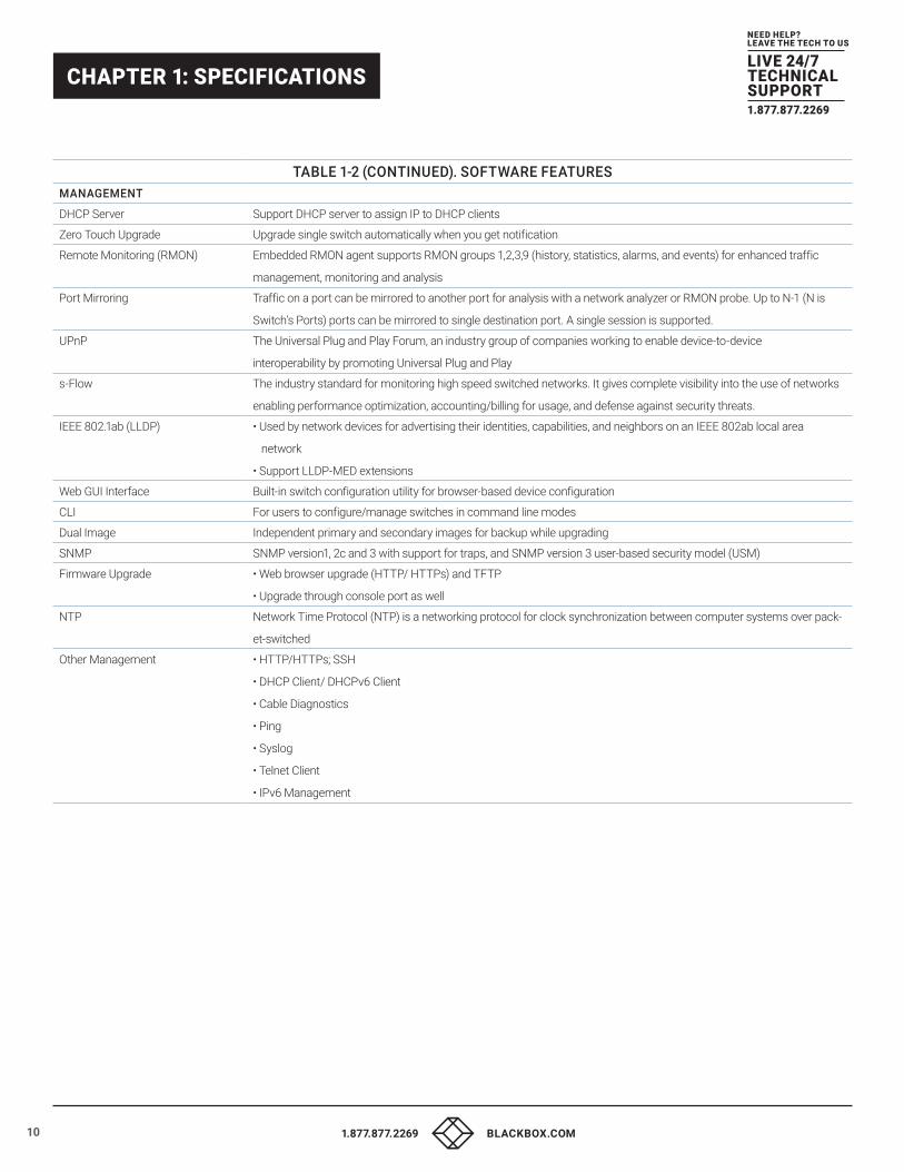
TABLE 1-2 (CONTINUED). SOFTWARE FEATURESMANAGEMENT
DHCP Server Support DHCP server to assign IP to DHCP clients
Zero Touch Upgrade Upgrade single switch automatically when you get notification
Remote Monitoring (RMON) Embedded RMON agent supports RMON groups 1,2,3,9 (history, statistics, alarms, and events) for enhanced traffic
management, monitoring and analysis
Port Mirroring Traffic on a port can be mirrored to another port for analysis with a network analyzer or RMON probe. Up to N-1 (N is
Switch’s Ports) ports can be mirrored to single destination port. A single session is supported.
UPnP The Universal Plug and Play Forum, an industry group of companies working to enable device-to-device
interoperability by promoting Universal Plug and Play
s-Flow The industry standard for monitoring high speed switched networks. It gives complete visibility into the use of networks
enabling performance optimization, accounting/billing for usage, and defense against security threats.
IEEE 802.1ab (LLDP) • Used by network devices for advertising their identities, capabilities, and neighbors on an IEEE 802ab local area
network
• Support LLDP-MED extensions
Web GUI Interface Built-in switch configuration utility for browser-based device configuration
CLI For users to configure/manage switches in command line modes
Dual Image Independent primary and secondary images for backup while upgrading
SNMP SNMP version1, 2c and 3 with support for traps, and SNMP version 3 user-based security model (USM)
Firmware Upgrade • Web browser upgrade (HTTP/ HTTPs) and TFTP
• Upgrade through console port as well
NTP Network Time Protocol (NTP) is a networking protocol for clock synchronization between computer systems over pack-
et-switched
Other Management • HTTP/HTTPs; SSH
• DHCP Client/ DHCPv6 Client
• Cable Diagnostics
• Ping
• Syslog
• Telnet Client
• IPv6 Management

11
NEED HELP?LEAVE THE TECH TO US
LIVE 24/7TECHNICALSUPPORT1.877.877.2269
1.877.877.2269 BLACKBOX.COM
CHAPTER 2: OVERVIEW
2.1 DESCRIPTION The Gigabit Managed Ethernet Switches are affordable managed switches that provide a reliable infrastructure for your business network. These switches deliver the intelligent features you need to improve the availability of your critical business applications, protect your sensitive information, and optimize your network bandwidth to deliver information and applications more effectively. Easy to set up and use, the switches are ideal for entry- level networking, including small business or enterprise applications.
The Gigabit Managed Ethernet Switches have 10, 26, or 48 ports. The switches provide advanced security management capabilities and network features that support data, voice, security, and wireless technologies.
Three Gigabit Managed Ethernet Switch models are available:
�� Gigabit Managed Ethernet Switch - 10-Ports (LGB1110A)
�� Gigabit Managed Ethernet Switch - 26-Ports (LGB1126A-R2)
�� Gigabit Managed Ethernet Switch - 52-Ports (LGB1152A)
2.2 SWITCH ARCHITECTURE The switch transports multiple wire-speed packets at low latency on all ports simultaneously. The switch also features full-duplex capability on all ports, which effectively doubles the bandwidth of each connection.
This switch uses store-and-forward technology to ensure maximum data integrity. With this technology, the entire packet must be received into a buffer and checked for validity before being forwarded. This prevents errors from being propagated throughout the network.
2.3 NETWORK MANAGEMENT OPTIONS The switch can also be managed over the network with a web browser or Telnet application. The switch includes a built-in network management agent that allows it to be managed in-band using SNMP or RMON (Groups 1, 2, 3, 9) protocols. It also has an RJ-45 console port connector on the front panel for out-of-band management. You can connect a PC to this port for configuration and monitoring out-of-band via a null-modem serial cable.
NOTE: For a detailed description of the management features, refer to the user’s manual.

12
NEED HELP?LEAVE THE TECH TO US
LIVE 24/7TECHNICALSUPPORT1.877.877.2269
1.877.877.2269 BLACKBOX.COM
CHAPTER 2: OVERVIEW
2.4 HARDWARE DESCRIPTION
2.4.1 1000BASE-T PORTS The RJ-45 ports on the switch support automatic MDI/MDI-X operation, auto-negotiation, and IEEE 802.3x auto-negotiation of flow control; it selects the optimum data rate and transmission automatically.
2.4.2 SFP TRANSCEIVER SLOTS The Gigabit Managed Ethernet Switch supports Small Form Factor Pluggable (SFP) transceiver slots. In the default configuration, if an SFP transceiver (purchased separately) is installed in a slot and has a valid link on the port, the associated RJ-45 port is disabled.
The following table shows a list of transceiver types that have been tested with the switch.
TABLE 2-1. SUPPORTED SFP TRANSCEIVERS
PART NUMBER DESCRIPTION
LFP411 SFP, 1250-Mbps Fiber with Extended Diagnostics, 850-nm Multimode, LC, 550 m
LFP412 SFP, 1250-Mbps Fiber with Extended Diagnostics, 1310-nm Multimode, LC, 2 km
LFP413 SFP, 1250-Mbps Fiber with Extended Diagnostics, 1310-nm Single-mode, LC, 10 km
LFP414 SFP, 1250-Mbps Fiber with Extended Diagnostics, 1310-nm Single-Mode, LC, 30 km
LFP418 SFP, 1250-Mbps Fiber with Extended Diagnostics, 1550-nm Single-Mode, LC, 80 km
LFP420 SFP, Simplex, 1250-Mbps Fiber with Extended Diagnostics, 1550-nm TX, 1310-nm RX, Single-Mode, LC, 10 km
2.4.3 PORT AND SYSTEM STATUS LEDS The Gigabit Managed Ethernet Switch switch includes a display panel for system and port indications that simplify installation and network troubleshooting. The LEDs are located on left hand side of the front panel for easy viewing. Details are shown below and described in the following tables.
TABLE 2-2. STATUS LEDS
LED CONDITION STATUS
Link/Act/Speed LED Green Lit green when all LEDS for each port are in Link/Act/Speed mode
Power LED GreenLit when switch is powering up; OFF when switch power is turned off

13
NEED HELP?LEAVE THE TECH TO US
LIVE 24/7TECHNICALSUPPORT1.877.877.2269
1.877.877.2269 BLACKBOX.COM
CHAPTER 3: NETWORK PLANNING
3.1 INTRODUCTION TO SWITCHING A network switch allows simultaneous transmission of multiple packets; it can partition a network more efficiently than bridges or routers.
When performance bottlenecks are caused by congestion at the network access point such as a file server, the device can be connected directly to a switched port. Using full-duplex mode, the bandwidth of the dedicated segment can be doubled to maximize throughput.
When networks are based on repeater (hub) technology, the distance between end stations is limited by a maximum hop count. A switch can subdivide the network into smaller and more manageable segments, and link them to the larger network so the hop count turns back to zero and removes the limitation.
A switch can be easily configured in any Ethernet, Fast Ethernet, or Gigabit Ethernet network to significantly increase bandwidth while using conventional cabling and network cards.
3.2 APPLICATION EXAMPLES The Gigabit Managed Ethernet Switch has 8, 24, or 48 Gigabit Ethernet TP ports with auto MDI-X. The LGB1110A and LGB1126A-R2 each have (2) dual-media ports, each consisting of (1) RJ-45 (100/1000 Mbps) and (1) SFP slot for a removable SFP module. The LGB1152A has (4) SFP (100/1000) slots.
The switch is suitable for the following applications.
�� Remote site for Enterprise or SMB
�� Peer-to-peer for two remote offices
�� Office network
�� High-performance environment
�� Advanced security for network safety
�� Data/voice and video conferencing

14
NEED HELP?LEAVE THE TECH TO US
LIVE 24/7TECHNICALSUPPORT1.877.877.2269
1.877.877.2269 BLACKBOX.COM
CHAPTER 4. INSTALLING THE SWITCH
4.1 SELECTING A SITE The switch can be mounted in a standard 19-inch equipment rack (via an optional rackmount kit) or on a flat surface. Follow the guidelines below when choosing a location.
The site should:
�� Be at the center of all the devices you want to link and near a power outlet.
�� Be able to maintain its temperature within 0 to 45°C (32 to 113 °F) and its humidity within 10% to 90%, non-condensing.
�� Be accessible for installing, cabling, and maintaining the devices.
�� Allow the status LEDs to be clearly visible.
�� Make sure the twisted-pair Ethernet cable is always routed away from power lines, radios, transmitters, or any other electrical interference.
�� Make sure that Gigabit Managed Ethernet Switch is connected to a separate grounded power outlet that provides 100 to 240 VAC, 50 to 60 Hz.
4.2 ETHERNET CABLING To ensure proper operation when installing the switch into a network, make sure that the current cables are suitable for 100BASE-TX or 1000BASE-T operation. Check the following criteria against the current installation of your network:
�� Cable type: Use unshielded twisted pair (UTP) or shielded twisted pair (STP) cable with RJ-45 connectors, Category 5 or Category 5e with maximum length of 328 feet (100 meters) for 100BASE-TX, and Category 5e or 6 with maximum length of 328 feet (100 meters) for 1000BASE-T.
�� Protection from radio frequency interference emissions.
�� Electrical surge suppression.
�� Separation of electrical wires and data based network wiring.
�� Safe connections with no damaged cables, connectors or shields.
4.3 EQUIPMENT CHECKLIST After unpacking this switch, please check the contents to be sure you have received all the components. Then, before beginning the installation, be sure you have all other necessary installation equipment.
4.4 PACKAGE CONTENTS
�� Gigabit Managed Ethernet Switch
�� Four adhesive rubber feet
�� Mounting kit (for 19” Rack Shelf, Optional)
�� This Installation Guide
�� AC power cord
�� RJ-45 console cable
WARNING: The SFP ports are Class 1 laser devices. Avoid direct eye exposure to the beam coming from the transmit port.

15
NEED HELP?LEAVE THE TECH TO US
LIVE 24/7TECHNICALSUPPORT1.877.877.2269
1.877.877.2269 BLACKBOX.COM
CHAPTER 4. INSTALLING THE SWITCH
4.5 MOUNTING
The switch can be mounted in a standard 19-inch equipment rack or on a desktop or shelf. Mounting instructions for each type of site as follows.
4.5.1 RACKMOUNTING Before rack mounting the switch, please pay attention to the following factors:
�� Temperature: Since the temperature within a rack assembly may be higher than the ambient room temperature, check that the rack environment temperature is within the specified operating temperature range 32 to 104* F (0 to 45 °C).
�� Mechanical Loading: Do not place any equipment on top of a rackmounted unit.
�� Circuit Overloading: Be sure that the supply circuit to the rack assembly is not overloaded.
�� Grounding: Rackmounted equipment should be properly grounded.
To rackmount devices:
STEP 1: Attach the brackets to the device using the screws provided in the mounting kit.
FIGURE 4-1. ATTACHING THE BRACKETS.

16
NEED HELP?LEAVE THE TECH TO US
LIVE 24/7TECHNICALSUPPORT1.877.877.2269
1.877.877.2269 BLACKBOX.COM
CHAPTER 4. INSTALLING THE SWITCH
STEP 2: Mount the device in the rack (via the optional rackmount kit), using four rackmounting screws (not provided). Be sure to secure the lower rackmounting screws first to prevent the brackets from bending caused by the weight of the switch.
FIGURE 4-2. INSTALLING THE SWITCH IN A RACK
STEP 3: If you are installing a single switch only, turn to “Connecting to a Power Source at the end of this chapter.
STEP 4: If you are installing multiple switches, mount them in the rack, one below the other, in any order.
4.5.2 DESKTOP OR SHELF MOUNTING STEP 1: Attach the four adhesive rubber feet to the bottom of the first switch.
STEP 2: Set the device on a flat surface near an AC power source, making sure there are at least two inches of space on all sides for proper air flow.
STEP 3: If you are installing a single switch only, go to “Connecting to a Power Source” at the end of this chapter.
STEP 4: If you are installing multiple switches, attach four adhesive feet to each one. Place each device squarely on top of the one below, in any order.

17
NEED HELP?LEAVE THE TECH TO US
LIVE 24/7TECHNICALSUPPORT1.877.877.2269
1.877.877.2269 BLACKBOX.COM
CHAPTER 4. INSTALLING THE SWITCH
4.6 INSTALLING AN OPTIONAL SFP TRANSCEIVER You can install or remove an SFP transceiver from an SFP transceiver slot slot without powering off the switch.
NOTES:
�� On the LGB1110A and LGB1126A-R2, the SFP slots are shared with the two 10/100/1000BASE-T RJ-45 ports. If an SFP is installed in a slot, the associated RJ-45 port is disabled and cannot be used.
�� The SFP ports operate only at full-duplex. Half-duplex operation is not supported.
�� Make sure network cable is NOT connected when you install or remove an SFP module.
CAUTION: Use only supported SFP modules with your switch.
NOTE: SFP transceivers are not included with the switch (you need to order them separately).
TABLE 4-1. SUPPORTED SFP TRANSCEIVERS
PART NUMBER DESCRIPTION
LFP411 SFP, 1250-Mbps Fiber with Extended Diagnostics, 850-nm Multimode, LC, 550 m
LFP412 SFP, 1250-Mbps Fiber with Extended Diagnostics, 1310-nm Multimode, LC, 2 km
LFP413 SFP, 1250-Mbps Fiber with Extended Diagnostics, 1310-nm Single-mode, LC, 10 km
LFP414 SFP, 1250-Mbps Fiber with Extended Diagnostics, 1310-nm Single-Mode, LC, 30 km
LFP418 SFP, 1250-Mbps Fiber with Extended Diagnostics, 1550-nm Single-Mode, LC, 80 km
LFP420 SFP, Simplex, 1250-Mbps Fiber with Extended Diagnostics, 1550-nm TX, 1310-nm RX, Single-Mode, LC, 10 km
TO INSTALL AN SFP TRANSCEIVER, FOLLOW THESE STEPS:
STEP 1: Consider network and cabling requirements to select an appropriate SFP transceiver type.
STEP 2: Insert the transceiver with the optical connector facing outward and the slot connector facing down. Note that SFP transceivers are keyed so they can only be installed in one orientation.
STEP 3: Slide the SFP transceiver into the slot until it clicks into place.
NOTE: SFP transceivers are not included with the switch (you need to order them separately).
4.7 CONNECTING TO A POWER SOURCE You can plug or remove the power cord from AC power socket to turn the switch power on and off.
STEP 1: Insert the power cable plug directly into the AC socket located on the back of the switch.
STEP 2: Plug the other end of the cable into a grounded, 3-Pin, AC power source.
STEP 3: Make sure the POWER LED on the switch is lit. If not, check that the power cable is correctly plugged in.
WARNING: For International use, you may need to change the AC line cord. You must use a line cord set that has been approved for the socket type in your country.
18
NEED HELP?LEAVE THE TECH TO US
LIVE 24/7TECHNICALSUPPORT1.877.877.2269
1.877.877.2269 BLACKBOX.COM
CHAPTER 4. INSTALLING THE SWITCH
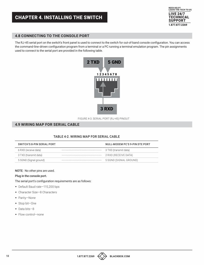
4.8 CONNECTING TO THE CONSOLE PORT The RJ-45 serial port on the switch’s front panel is used to connect to the switch for out-of-band console configuration. You can access the command-line-driven configuration program from a terminal or a PC running a terminal emulation program. The pin assignments used to connect to the serial port are provided in the following table.
2 TXD
3 RXD
5 GND
1 2 3 4 5 6 7 8
FIGURE 4-3. SERIAL PORT (RJ-45) PINOUT
4.9 WIRING MAP FOR SERIAL CABLE
TABLE 4-2. WIRING MAP FOR SERIAL CABLE
SWITCH’S 8-PIN SERIAL PORT NULL-MODEM PC’S 9-PIN DTE PORT
6 RXD (receive data) --------------------------------------------- 3 TXD (transmit data)
3 TXD (transmit data) --------------------------------------------- 2 RXD (RECEIVE DATA)
5 SGND (Signal ground) --------------------------------------------- 5 SGND (SIGNAL GROUND)
NOTE: No other pins are used.
Plug in the console port.
The serial port’s configuration requirements are as follows:
�� Default Baud rate—115,200 bps
�� Character Size—8 Characters
�� Parity—None
�� Stop bit—One
�� Data bits—8
�� Flow control—none

19
NEED HELP?LEAVE THE TECH TO US
LIVE 24/7TECHNICALSUPPORT1.877.877.2269
1.877.877.2269 BLACKBOX.COM
CHAPTER 4. INSTALLING THE SWITCH
4.10 OPERATION OF WEB-BASED MANAGEMENT The default values of the switch are listed below:
IP address: 192.168.1.1
Subnet mask: 255.255.255.0
Default gateway: 192.168.1.254
Username: admin
Password: <blank>
To access the web management of the switch, enter the default IP address in the web browser and press enter.
Example: http://192.168.1.1
Once you enter the IP address into the web browser, you will be prompted to enter a username and password to access the web management interface. Enter the default values:
Username: admin
Password: <blank>
For full configuration details of the switch, refer to the user’s manual.

20
NEED HELP?LEAVE THE TECH TO US
LIVE 24/7TECHNICALSUPPORT1.877.877.2269
1.877.877.2269 BLACKBOX.COM
CHAPTER 5: MAKING NETWORK CONNECTIONS
5.1 CONNECTING NETWORK DEVICES The switch is designed to be connected to 10, 100, or 1000 Mbps network cards in PCs and servers, as well as to other switches and hubs. It may also be connected to remote devices using optional SFP transceivers.
5.2 TWISTED-PAIR DEVICES Each device requires an unshielded twisted-pair (UTP) cable with RJ-45 connectors at both ends. Use Category 5, 5e, or 6 cables for 1000BASE-T connections, Category 5 or better for 100BASE-TX connections.
5.3 CABLING GUIDELINES The RJ-45 ports on the switch support automatic MDI/MDI-X pinout configuration, so you can use standard straight-through twisted-pair cables to connect to any other network device (PCs, servers, switches, routers, or hubs).
CAUTION: Do not plug a phone jack connector into an RJ-45 port. This will damage the switch. Use only twisted-pair cables with RJ-45 connectors that conform to FCC standards.
5.4 CONNECTING TO PCS, SERVERS, HUBS, AND SWITCHES STEP 1: Attach one end of a twisted-pair cable segment to the device’s RJ-45 connector.
STEP 2: . If the device is a network card and the switch is in the wiring closet, attach the other end of the cable segment to a modular wall outlet that is connected to the wiring closet. (See the section “Network Wiring Connections.”) Otherwise, attach the other end to an available port on the switch.
Make sure each twisted pair cable does not exceed 100 meters (328 ft) in length.
NOTE: Avoid using flow control on a port connected to a hub unless it is actually required to solve a problem. Otherwise, backpressure jamming signals may degrade overall performance for the segment attached to the hub.
STEP 3: As each connection is made, the Link LED (on the switch) corresponding to each port will light green (1000 Mbps) or amber (100 Mbps) to indicate that the connection is valid.

21
NEED HELP?LEAVE THE TECH TO US
LIVE 24/7TECHNICALSUPPORT1.877.877.2269
1.877.877.2269 BLACKBOX.COM
CHAPTER 5: MAKING NETWORK CONNECTIONS
5.5 NETWORK WIRING CONNECTIONS The punchdown block is an integral part of many equipment racks. It is actually part of the patch panel. Instructions for making connections in the wiring closet with this type of equipment follow.
STEP 1: Attach one end of a patch cable to an available port on the switch, and connect the other end to the patch panel.
STEP 2: If not already in place, attach one end of a cable segment to the back of the patch panel where the punch-down block is located, and the other end to a modular wall outlet.
STEP 3: Label the cables to simplify future troubleshooting. See “Cable Labeling and Connection Records.”
FIGURE 5-1. NETWORK WIRING CONNECTIONS

22
NEED HELP?LEAVE THE TECH TO US
LIVE 24/7TECHNICALSUPPORT1.877.877.2269
1.877.877.2269 BLACKBOX.COM
CHAPTER 5: MAKING NETWORK CONNECTIONS
5.6 FIBER OPTIC SFP DEVICES An optional Gigabit SFP transceiver can be used for a backbone connection between switches, or for connecting to a high-speed server.
Each single-mode fiber port requires 9/125 micron single-mode fiber optic cable with an LC connector at both ends. Each multimode fiber optic port requires 50/125 or 62.5/125 micron multimode fiber optic cabling with an LC connector at both ends.
WARNING: This switch uses lasers to transmit signals over fiber optic cable. The lasers are inherently eye-safe in normal operation. However, user should never look directly at a transmit port when it is powered on.
WARNING: When selecting a fiber SFP device, consider safety. Make sure that it can function at a temperature that is not less than the recommended maximum operational temperature of the product. You must also use an approved Laser SFP transceiver.
STEP 1: Remove and keep the LC port’s rubber plug. When not connected to a fiber cable, the rubber plug should be replaced to protect the optics.
STEP 2: Check that the fiber terminators are clean. You can clean the cable plugs by wiping them gently with a clean tissue or cotton ball moistened with a little ethanol. Dirty fiber terminators on fiber optic cables will impair the quality of the light transmitted through the cable and lead to degraded performance on the port.
STEP 3: Connect one end of the cable to the LC port on the switch and the other end to the LC port on the other device. Since LC connectors are keyed, the cable can be attached in only one orientation.
STEP 4: As a connection is made, check the Link LED on the switch corresponding to the port to be sure that the connection is valid.
The fiber optic ports operate at 1 Gbps. The maximum length for fiber optic cable operating at Gigabit speed will depend on the fiber type as listed under “1000 Mbps Gigabit Ethernet Collision Domain.”
5.7 CONNECTIVITY RULES When adding hubs to your network, please note that because switches break up the path for connected devices into separate collision domains, you should not include the switch or connected cabling in your calculations for cascade length involving other devices.
5.8 1000BASE-T CABLE REQUIREMENTS All Category 5 UTP cables that are used for 100BASE-TX connections should also work for 1000BASE-T, providing that all four wire pairs are connected. We recommend that for all critical connections, or any new cable installations, Category 5e or Category 6 cable should be used. The Category 5e and 6 specifications include test parameters that are only recommendations for Category 5. The first step in preparing existing Category 5 cabling for running 1000BASE-T is a simple test of the cable installation to be sure that it complies with the IEEE 802.3-2005 standards.
5.9 1000-MBPS GIGABIT ETHERNET COLLISION DOMAIN
TABLE 5-1. MAXIMUM 1000BASE-T GIGABIT ETHERNET CABLE LENGTH
CABLE TYPE MAXIMUM CABLE LENGTH CONNECTOR
Category 5, 5e or 6 100-ohm UTP or STP 100.m (328 ft) RJ-45
Power LED GreenLit when switch is powering up; OFF when switch power is turned off

23
NEED HELP?LEAVE THE TECH TO US
LIVE 24/7TECHNICALSUPPORT1.877.877.2269
1.877.877.2269 BLACKBOX.COM
CHAPTER 5: MAKING NETWORK CONNECTIONS
TABLE 5-2. MAXIMUM 1000BASE-SX GIGABIT FIBER CABLE LENGTHS
FIBER SIZE FIBER BANDWIDTH MAXIMUM CABLE LENGTH CONNECTOR
62.5/125 micron multimode fiber160 MHz/km
200 MHz/km
220 m (722 ft)
275 m (902 ft)
LC
LC
50/125 micron multimode fiber400 MHz/km
500 MHz/km
500 m (1641 ft)
550 m (1805 ft)
LC
LC
TABLE 5-3. MAXIMUM 1000BASE-LX/LHX/XD/ZX GIGABIT FIBER CABLE LENGTH
FIBER SIZE FIBER BANDWIDTH MAXIMUM CABLE LENGTH CONNECTOR
9/125 micron single-mode fiber 1310 nm N/A 10 km (6.2 miles) LC
9/125 micron single-mode fiber 1550 nm N/A30 km (18.64 miles)
50 km (31.06 miles)
LC
LC
TABLE 5-4. MAXIMUM 1000BASE-LX SINGLE FIBER GIGABIT FIBER CABLE LENGTH
FIBER SIZE FIBER BANDWIDTH MAXIMUM CABLE LENGTH CONNECTOR
Single-modeTX-1310 nm
RX-1550 nm
N/A
20 km (12.42 miles)
BIDI
LC
Single-modeTX-1550 nm
RX-1310 nm
N/A
20 km (12.42 miles)
BIDI
LC
5.10 100-MBPS FAST ETHERNET COLLISION DOMAIN
TABLE 5-5. MAXIMUM FAST ETHERNET CABLE LENGTHS
CABLE TYPE MAXIMUM CABLE LENGTH CONNECTOR
Category 5, 5e or 6 100-ohm UTP or STP 100.m (328 ft) RJ-45

24
NEED HELP?LEAVE THE TECH TO US
LIVE 24/7TECHNICALSUPPORT1.877.877.2269
1.877.877.2269 BLACKBOX.COM
CHAPTER 6: CABLE LABELING AND CONNECTION RECORDS
When planning a network installation, it is essential to label the opposing ends of cables and to record where each cable is connected. This will allow a user to easily locate interconnected devices, isolate faults, and change your topology without spending unnecessary time.
To best manage the physical implementations of your network, follow these guidelines:
�� Clearly label the opposing ends of each cable.
�� Using your building’s floor plans, draw a map of the location of all network-connected equipment. For each piece of equipment, identify the devices to which it is connected.
�� Note the length of each cable and the maximum cable length supported by the switch ports.
�� Use a location-based key when assigning prefixes to your cable labeling.
�� Use sequential numbers for cables that originate from the same equipment.
�� Differentiate between racks by naming accordingly.
�� Label each separate piece of equipment.
�� Display a copy of your equipment map, including keys to all abbreviations at each equipment rack.

25
NEED HELP?LEAVE THE TECH TO US
LIVE 24/7TECHNICALSUPPORT1.877.877.2269
1.877.877.2269 BLACKBOX.COM
CHAPTER 7: TROUBLESHOOTING
7.1 BASIC TROUBLESHOOTING TIPS Most problems are caused by the following situations. Check for these items first when starting your troubleshooting:
�� Connecting to devices that have a fixed full-duplex configuration.
�� The RJ-45 ports are configured as “Auto.” That is, when connecting to attach devices, the switch will operate in one of two ways to determine the link speed and the communication mode (half-duplex or full-duplex):
�� If the connected device is also configured to Auto-Negotiation, the switch will automatically negotiate both link speed and communication mode.
�� If the connected device has a fixed configuration, for example 100 Mbps, at half- or full-duplex, the switch will automatically sense the link speed, but will default to a communication mode of half-duplex.
Because the switch behaves in this way (in compliance with the IEEE 802.3 standard), if a device connected to the switch has a fixed configuration of full-duplex, the device will not connect correctly to the switch. The result will be high error rates and very inefficient communications between the switch and the device.
Make sure all devices connected to the switch are configured to auto-negotiate, or are configured to connect at half-duplex (all hubs are configured this way, for example).
�� Faulty or loose cables. Look for loose or obviously faulty connections. If they appear to be OK, make sure the connections are snug. If that does not correct the problem, try a different cable.
�� Non-standard cables. Non-standard and miswired cables may cause network collisions and other network problems, and can seriously impair network performance. Use a new correctly-wired cable. To ensure correct pinouts and cable wiring, we recommend using a Category 5 cable tester for every 100BASE-TX and 1000BASE-T network installation.
�� Improper Network Topologies. Make sure you have a valid network topology. If you no longer experience the problems, the new topology is probably at fault. In addition, you should make sure that your network topology contains no data path loops.
�� Check the port configuration: A port on your switch may not be operating as you expect because it has been put into a “blocking” state by Spanning Tree, GVRP (automatic VLANs), or LACP (automatic trunking). (Note that the normal operation of the Spanning Tree, GVRP, and LACP features may put the port in a blocking state.) The port just may have been configured as disabled through software.
7.2 TROUBLESHOOTING CHART
TABLE 7-1. TROUBLESHOOTING CHART
SYMPTOM ACTION
POWER LED is Off• Check connections between the switch, the power cord and the wall outlet.
• Contact Black Box Technical Support at 877-877-2269 or [email protected] for assistance.
Link LED is Off
• Verify that the switch and attached device are powered on.
• Make sure the cable is plugged into the switch and corresponding device.
• If the switch is installed in a rack, check the connections to the punchdown block and patch panel.
• Verify that the proper cable types is used and its length does not exceed specified limits.
• Check the adapter on the attached device and cable connections for possible defects. Replace the defective adapter or cable
if necessary.

26
NEED HELP?LEAVE THE TECH TO US
LIVE 24/7TECHNICALSUPPORT1.877.877.2269
1.877.877.2269 BLACKBOX.COM
CHAPTER 8: POWER AND COOLING PROBLEMS
8.1 INSTALLATION If the power indicator does not turn on when the power cord is plugged in, you may have a problem with the power outlet, power cord, or internal power supply. However, if the unit powers off after running for a while, check for loose power connections, power losses or surges at the power outlet. If you still cannot isolate the problem, the internal power supply may be defective. Verify that all system components have been properly installed. If one or more components appear to be malfunctioning (such as the power cord or network cabling), test them in an alternate environment where you are sure that all the other components are functioning properly.
8.2 IN-BAND ACCESS You can access the management agent in the switch anywhere within the attached network using Telnet, a web browser. However, you must first configure the switch with a valid IP address, subnet mask, and default gateway. If you have trouble establishing a link to the management agent, check to see if you have a valid network connection. Then verify that you entered the correct IP address. Also, make sure the port through which you are connecting to the switch has not been disabled. If it has not been disabled, then check the network cabling that runs between your remote location and the switch
NOTE: The management agent accepts up to four simultaneous Telnet sessions. If the maximum number of sessions already exists, an additional Telnet connection will not be able to log into the system.

27
NEED HELP?LEAVE THE TECH TO US
LIVE 24/7TECHNICALSUPPORT1.877.877.2269
1.877.877.2269 BLACKBOX.COM
CHAPTER 9: CABLES
9.1 TWISTED-PAIR CABLE AND PIN ASSIGNMENTS For 10/100BASE-TX connections, the twisted-pair cable must have two pairs of wires. For 1000BASE-T connections, the twisted-pair cable must have four pairs of wires. Each wire pair is identified by two different colors. For example, one wire might be green and the other green with white stripes. Also, an RJ-45 connector must be attached to both ends of the cable
CAUTION: DO NOT plug a phone jack connector into any RJ-45 port. Use only twisted-pair cables with RJ-45 connectors that conform to FCC standards.
CAUTION: Each wire pair must be attached to the RJ-45 connectors in a specific orientation
The next figure illustrates how the pins on the RJ-45 connector are numbered. Be sure to hold the connectors in the same orientation when attaching the wires to the pins.
FIGURE 9-1. RJ-45 CONNECTOR PIN NUMBERS
9.2 10BASE-T/100BASE-TX PIN ASSIGNMENTS Use unshielded twisted-pair (UTP) or shielded twisted-pair (STP) cable for RJ-45 connections: 100-ohm Category 3 or better cable for 10 Mbps connections, or 100-ohm Category 5 or better cable for 100 Mbps connections. Also make sure that the length of any twisted-pair connection does not exceed 100 meters (328 feet).
The RJ-45 ports on the switch base unit support automatic MDI/MDI-X operation, so you can use straight-through cables for all network connections to PCs or servers, or to other switches or hubs. In straight-through cable, pins 1, 2, 3, and 6, at one end of the cable are connected straight through to pins 1, 2, 3, and 6 at the other end of the cable. When using any RJ-45 port on this switch, you can use either straight-through or crossover cable.
TABLE 9-1. 10/100BASE-TX MDI AND MDI-X PORT PINOUTS
PIN # MDI SIGNAL NAME MDI-X SIGNAL NAME
1 Transmit Data plus (TD+) Receive Data plus (RD+)
2 Transmit Data minus (TD-) Receive Data minus (RD-)
3 Receive Data plus (RD+) Transmit Data plus (TD+)
6 Receive Data minus (RD-) Transmit Data minus (TD-)
4, 5, 7, 8 Not used Not used
NOTE: The “+” and “-” signs represent the polarity of the wires that make up each wire pair.
28
NEED HELP?LEAVE THE TECH TO US
LIVE 24/7TECHNICALSUPPORT1.877.877.2269
1.877.877.2269 BLACKBOX.COM
CHAPTER 9: CABLES
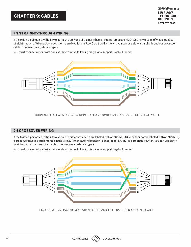
9.3 STRAIGHT-THROUGH WIRING If the twisted-pair cable will join two ports and only one of the ports has an internal crossover (MDI-X), the two pairs of wires must be straight-through. (When auto-negotiation is enabled for any RJ-45 port on this switch, you can use either straight-through or crossover cable to connect to any device type.)
You must connect all four wire pairs as shown in the following diagram to support Gigabit Ethernet.
12345678
12345678
FIGURE 9-2. EIA/TIA 568B RJ-45 WIRING STANDARD 10/100BASE-TX STRAIGHT-THROUGH CABLE
9.4 CROSSOVER WIRING If the twisted-pair cable will join two ports and either both ports are labeled with an “X” (MDI-X) or neither port is labeled with an “X” (MDI), a crossover must be implemented in the wiring. (When auto-negotiation is enabled for any RJ-45 port on this switch, you can use either straight-through or crossover cable to connect to any device type.)
You must connect all four wire pairs as shown in the following diagram to support Gigabit Ethernet.
12345678
12345678
FIGURE 9-3. EIA/TIA 568B RJ-45 WIRING STANDARD 10/100BASE-TX CROSSOVER CABLE

29
NEED HELP?LEAVE THE TECH TO US
LIVE 24/7TECHNICALSUPPORT1.877.877.2269
1.877.877.2269 BLACKBOX.COM
CHAPTER 9: CABLES
9.5 1000BASE-T PIN ASSIGNMENTS All 1000BASE-T ports support automatic MDI/MDI-X operation, so you can use straight-through cables for all network connections to PCs or servers, or to other switches or hubs.
The next table shows the 1000BASE-T MDI and MDI-X port pinouts. These ports require that all four pairs of wires be connected.
NOTE: For 1000BASE-T operation, all four pairs of wires are used for both transmit and receive.
Use 100-ohm Category 5, 5e, or 6 unshielded twisted-pair (UTP) or shielded twisted-pair (STP) cable for 1000BASE-T connections. Also be sure that the length of any twisted-pair connection does not exceed 100 meters (328 feet).
TABLE 9-2. 1000BASE-T MDI AND MDI-X PORT PINOUTS
PIN # MDI SIGNAL NAME MDI-X SIGNAL NAME
1 Bi-directional Pair A Plus (BI_DA+) Bi-directional Pair B Plus (BI_DB+)
2 Bi-directional Pair A Minus (BI_DA-) Bi-directional Pair B Minus (BI_DB-)
3 Bi-directional Pair B Plus (BI_DB+) Bi-directional Pair A Plus (BI_DA+)
4 Bi-directional Pair C Plus (BI_DC+) Bi-directional Pair D Plus (BI_DD+)
5 Bi-directional Pair C Minus (BI_DC-) Bi-directional Pair D Minus (BI_DD-)
6 Bi-directional Pair B Minus (BI_DB-) Bi-directional Pair A Minus (BI_DA-)
7 Bi-directional Pair D Plus (BI_DD+) Bi-directional Pair C Plus (BI_DC+)
8 Bi-directional Pair D Minus (BI_DD-) Bi-directional Pair C Minus (BI_DC-)
9.6 CABLE TESTING FOR EXISTING CATEGORY 5 CABLE Installed Category 5 cabling must pass tests for Attenuation, Near-End Crosstalk (NEXT), and Far-End Crosstalk (FEXT). This cable testing information is specified in the ANSI/TIA/EIA-TSB-67 standard. Additionally, cables must also pass test parameters for Return Loss and Equal-Level Far-End Crosstalk (ELFEXT). These tests are specified in the ANSI/TIA/EIA-TSB-95 Bulletin, “The Additional Transmission Performance Guidelines for 100 Ohm 4-Pair Category 5 Cabling.”
NOTE: That when testing your cable installation, be sure to include all patch cables between switches and end devices.
9.7 ADJUSTING EXISTING CATEGORY 5 CABLING TO RUN 1000BASE-T If your existing Category 5 installation does not meet one of the test parameters for 1000BASE-T, there are basically three measures that can be applied to try and correct the problem:
1. Replace any Category 5 patch cables with high-performance Category 5e or Category 6 cables.
2. Reduce the number of connectors used in the link.
3. Reconnect some of the connectors in the link.

30
NEED HELP?LEAVE THE TECH TO US
LIVE 24/7TECHNICALSUPPORT1.877.877.2269
1.877.877.2269 BLACKBOX.COM
CHAPTER 9: CABLES
9.8 FIBER STANDARDS The International Telecommunication Union (ITU-T) has standardized various fiber types for data networks. These are summarized in the following table.
TABLE 9-3. FIBER STANDARDS
ITU-T STANDARD DESCRIPTION APPLICATION
G.651Multimode Fiber: 50/125-micron core
Short-reach connections in the 1300- nm or 850-nm band
G.652Non-Dispersion-Shifted Fiber: Single-mode, 9/125-micron core
Longer spans and extended reach. Optimized for operation in the 1310- nm band. but can also be used in the 1550-nm band
G.652.CLow Water Peak Non- Dispersion-Shifted Fiber: Single-mode, 9/125-micron core
Longer spans and extended reach. Optimized for wavelength-division multiplexing (WDM) transmission across wavelengths from 1285 to 1625 nm. The zero dispersion wavelength is in the 1310-nm region.
G.653Dispersion-Shifted Fiber: Single-mode, 9/125-micron core
Longer spans and extended reach. Optimized for operation in the region from 1500 to 1600-nm.
G.6541550-nm Loss-Minimized Fiber: Single-mode, 9/125-micron core
Extended long-haul applications. Optimized for high-power transmission in the 1500 to 1600-nm region, with low loss in the 1550-nm band.
G.655Non-Zero Dispersion-Shifted Fiber: Single-mode, 9/125-micron core
Extended long-haul applications. Optimized for high-power dense wavelength-division multiplexing (DWDM) operation in the region from 1500 to 1600-nm.

31
NEED HELP?LEAVE THE TECH TO US
LIVE 24/7TECHNICALSUPPORT1.877.877.2269
1.877.877.2269 BLACKBOX.COM
CHAPTER 10: COMPLIANCES AND STANDARDS
10.1 COMPLIANCES All 1000BASE-T ports support automatic MDI/MDI-X operation, so you can use straight-through cables for all network connections to PCs or servers, or to other switches or hubs.
10.1.1 FCC RFI STATEMENT This equipment has been tested and found to comply with the limits for a Class A computing device pursuant to Subpart J of part 15 of FCC Rules, which are designed to provide reasonable protection against such interference when operated in a commercial environment.
This equipment generates, uses, and can radiate radio frequency energy and, if not installed and used in accordance with the instruction manual, may cause harmful interference to radio communications. Operation of this equipment in a residential area is likely to cause harmful interference in which case the user will be required to correct the interference at his own expense.
You are cautioned that changes or modifications not expressly approved by the party responsible for compliance could void your authority to operate the equipment.
You may use unshielded twisted-pair (UTP) for RJ-45 connections – Category 3 or better for 10 Mbps connections, Category 5 or better for 100 Mbps connections, Category 5, 5e, or 6 for 1000 Mbps connections. For fiber optic connections, you may use 50/125 or 62.5/125 micron multimode fiber or 9/125 micron single-mode fiber.
10.1.2 CE MARK DECLARATION OF CONFORMANCE FOR EMI AND SAFETY (EEC) This equipment has been tested and found to comply with the protection requirements of European Emission Standard EN55022/EN61000-3 and the Generic European Immunity Standard EN55024.
�� EMC: EN55022(2006)+A1:2007/CISPR 22:2006+A1:2006: Class A 4K V CD, 8KV, AD
�� IEC61000-4-2 (2001): 3V/m
�� IEC61000-4-3( 2002): 1KV – (power line), 0.5KV – (signal line)
�� IEC61000-4-4(2004): Line to Line: 1KV, Line to Earth: 2KV
�� IEC61000-4-5 (2001): 130dBuV(3V) Level 2
�� IEC61000-4-6 (2003): 1A/m
�� IEC61000-4-8 (2001): Voltage dips: >95%, 0.5 period, 30%, 25 periods
�� IEC61000-4-11(2001): Voltage interruptions: >95%, 250 periods
10.2 STANDARDS
�� 10BASE-T: IEEE 802.3 specification for 10 Mbps Ethernet over two pairs of Category 3, 4, or 5 UTP cable.
�� 100BASE-TX: IEEE 802.3u specification for 100 Mbps Ethernet over two pairs of Category 5 UTP cable.
�� 1000BASE-LH: Specification for long-haul Gigabit Ethernet over two strands of 9/125 micron core fiber cable
�� 1000BASE-LX: IEEE 802.3z specification for Gigabit Ethernet over two strands of 50/125, 62.5/125 or 9/125 micron core fiber cable
�� 1000BASE-SX: IEEE 802.3z specification for Gigabit Ethernet over two strands of 50/125 or 62.5/125 micron core fiber cable
�� 1000BASE-T: IEEE 802.3ab specification for Gigabit Ethernet over 100-ohm Category 5, 5e or 6 twisted-pair cable (using all four wire pairs)
�� Auto-Negotiation: Signaling method allowing each node to select its optimum operational mode (e.g., speed and duplex mode) based on the capabilities of the node to which it is connected

32
NEED HELP?LEAVE THE TECH TO US
LIVE 24/7TECHNICALSUPPORT1.877.877.2269
1.877.877.2269 BLACKBOX.COM
CHAPTER 10: COMPLIANCES AND STANDARDS
10.2 STANDARDS (CONTINUED)
�� Bandwidth: The difference between the highest and lowest frequencies available for network signals. Also synonymous with wire speed, the actual speed of the data transmission along the cable.
�� Collision Domain: Single CSMA/CD LAN segment.
�� CSMA/CD: CSMA/CD (Carrier Sense Multiple Access/Collision Detect) is the communication method employed by Ethernet, Fast Ethernet, and Gigabit Ethernet.
�� End Station: A workstation, server, or other device that does not forward traffic
�� Ethernet: A network communication system developed and standardized by DEC, Intel, and Xerox, were using baseband transmission, CSMA/CD access, logical bus topology, and coaxial cable. The successor IEEE 802.3 standard provides for integration into the OSI model and extends the physical layer and media with repeaters and implementations that operate on fiber, thin coax and twisted-pair cable.
�� Fast Ethernet: A 100 Mbps network communication system based on Ethernet and the CSMA/ CD access method.
�� Full-duplex: Transmission method that allows two network devices to transmit and receive concurrently, effectively doubling the bandwidth of that link
�� Gigabit Ethernet: A 1000 Mbps network communication system based on Ethernet and the CSMA/ CD access method.
�� IEEE: Institute of Electrical and Electronic Engineers
�� IEEE 802.3: Defines carrier sense multiple access with collision detection (CSMA/CD) access method and physical layer specifications
�� IEEE 802.3ab: Defines CSMA/CD access method and physical layer specifications for 1000BASE-T Gigabit Ethernet. (Now incorporated in IEEE 802.3-2005.)
�� IEEE 802.3u: Defines CSMA/CD access method and physical layer specifications for 100BASE- TX Fast Ethernet. (Now incorporated in IEEE 802.3-2005.)
�� IEEE 802.3x: Defines Ethernet frame start/stop requests and timers used for flow control on full-duplex links. (Now incorporated in IEEE 802.3-2005.)
�� IEEE 802.3z: Defines CSMA/CD access method and physical layer specifications for 1000BASE Gigabit Ethernet. (Now incorporated in IEEE 802.3-2005.)
�� LAN Segment: Separate LAN or collision domain.
�� LED: Light emitting diode used for monitoring a device or network condition
�� Local Area Network (LAN): A group of interconnected computer and support devices
�� Media Access Control (MAC): A portion of the networking protocol that governs access to the transmission medium, facilitating the exchange of data between network nodes.
�� MIB: An acronym for Management Information Base. It is a set of database objects that contains information about the device.
�� Modal Bandwidth: Bandwidth for multimode fiber is referred to as modal bandwidth because it varies with the modal field (or core diameter) of the fiber. Modal bandwidth is specified in units of MHz per km, which indicates the amount of bandwidth supported by the fiber for a one km distance.
�� Network Diameter: Wire distance between two end stations in the same collision domain
�� RJ-45 Connector: A connector for twisted-pair wiring.
�� Switched Ports: Ports that are on separate collision domains or LAN segments.
�� TIA: Telecommunications Industry Association.

33
NEED HELP?LEAVE THE TECH TO US
LIVE 24/7TECHNICALSUPPORT1.877.877.2269
1.877.877.2269 BLACKBOX.COM
CHAPTER 10: COMPLIANCES AND STANDARDS
�� Transmission Control Protocol/Internet Protocol (TCP/IP): Protocol suite that includes TCP as the primary transport protocol, and IP as the network layer protocol
�� User Datagram Protocol (UDP): UDP provides a datagram mode for the packet-switched communications. It uses the IP as the underlying transport mechanism to provide access to IP-like services. UDP packets are delivered just like IP packets—connection-less data grams that may be discarded before reaching their targets. UDP is useful when TCP would be too complex, too slow, or just unnecessary
�� UTP: Unshielded twisted-pair cable
�� Virtual LAN (VLAN): A Virtual LAN is a collection of network nodes that share the same collision domain regardless of their physical location or connection point in the network. A VLAN serves as a logical workgroup with no physical barriers, allowing users to share information and resources as though located on the same LAN.

34
NEED HELP?LEAVE THE TECH TO US
LIVE 24/7TECHNICALSUPPORT1.877.877.2269
1.877.877.2269 BLACKBOX.COM
NOTES
__________________________________________________________________________________________________
__________________________________________________________________________________________________
__________________________________________________________________________________________________
__________________________________________________________________________________________________
__________________________________________________________________________________________________
__________________________________________________________________________________________________
__________________________________________________________________________________________________
_
_________________________________________________________________________________________________
__________________________________________________________________________________________________
__________________________________________________________________________________________________\
__________________________________________________________________________________________________
__________________________________________________________________________________________________
__________________________________________________________________________________________________
__________________________________________________________________________________________________
_________________________________________________________________________________________________
__________________________________________________________________________________________________
__________________________________________________________________________________________________

35
NEED HELP?LEAVE THE TECH TO US
LIVE 24/7TECHNICALSUPPORT1.877.877.2269
1.877.877.2269 BLACKBOX.COM
NOTES
__________________________________________________________________________________________________
__________________________________________________________________________________________________
__________________________________________________________________________________________________
__________________________________________________________________________________________________
__________________________________________________________________________________________________
__________________________________________________________________________________________________
__________________________________________________________________________________________________
_
_________________________________________________________________________________________________
__________________________________________________________________________________________________
__________________________________________________________________________________________________\
__________________________________________________________________________________________________
__________________________________________________________________________________________________
__________________________________________________________________________________________________
__________________________________________________________________________________________________
_________________________________________________________________________________________________
__________________________________________________________________________________________________
__________________________________________________________________________________________________

© COPYRIGHT 2016 BLACK BOX CORPORATION. ALL RIGHTS RESERVED.
NEED HELP?LEAVE THE TECH TO US
LIVE 24/7TECHNICALSUPPORT1.877.877.2269