(lhd) u.s. department of energy
TRANSCRIPT

From:To: NSW Productivity FeedbackSubject: Regional rail - bi-mode technology obsoleteDate: Monday, 21 September 2020 3:44:26 PMAttachments: 990290.pdf
21/9/2020
Dear Productivity Commission,
The regional rail project is an important, expensive and long term project that locks assetsinto fuel use for significant periods of time. Getting the technology right for trains isessential.
From the outset, the plan to use bi-modal technology to reduce carbon emissions and costsis indeed moving in the right direction.
One of the largest costs for the NSW rail transport is the construction, maintenance andgenerated electricity supply to it's mostly urban trains, and the extension of those lines aspopulation grows.
Has the productivity Commission considered how much money could be saved byeliminating the need for train network electrification altogether?
The implementation of hydrogen fuel cell technology would allow an electric train to runon bi-modally either on the grid, or using the fuel cell in non electrified areas. Regionaltrains, or at least some of the regional trains for this project should be used as a pilotproject test case for making the train electricity grid work more cheaply and efficiently.
This could be used as a springboard to phase out the need for electricity on the train grid,or to use bi-modal city trains that allow the train electricity to be switched off as gridelectricity backup during peak demand. This would essentially function like a battery, orlike switching off an aluminium smelter in peak demand. It would also allow trains to usethe cheapest mode available at all times. Ie when solar energy peaks in the day, trains usegrid power where available (and perhaps generate hydrogen fuel for the trains wherepossible). When electricity is expensive, or where electrification is unnecessary orunavailable, trains use hydrogen.
Successful retrofitting of existing electric trains with hydrogen fuel cells to make them bi-modal might be quite easily achievable. The benefit may we far and above what theexisting has aimed to achieve.
If the current contractor for the regional trains could come up with a viable and testable bi-modal hydrogen fuel cell electric train system, the international interest and exportopportunities would be nothing short of astounding.
The economic benefits from this a hydrogen fuel cell - electric bi-modal trial, could beenormously far reaching, both in terms of train technology, intellectual property, andpossible exports of climate rail transition technology. This trial would ties in with thefoundations and demonstrations portion of the national hydrogen strategy, and link withhydrogen hub development through port Kembla.
Diesel just cannot offer any where near the same level of economic opportunity. Sydney isAustralia's global city, making its rail network state of the art and carbon neutral without

wasting existing infrastructure will position Australia's greater Sydney region as a major orthe major hydrogen innovation and supply capital of the world. Trials of a hydrogen fuelcell bi-modal trains is a great project for a first leap forward, and an advantage over otherhydrogen hubs.
If this train trial idea was leveraged through a hydrogen export/import terminal at PortKembla, and a hydrogen freight rail system through Dombarton, linking with a hydrogenrefueling station for aircraft at the Nancy Bird-Walton Airport in Western Sydney. Carbonneutral tourism may become an extremely important aspect of future tourismconsiderations, particularly as the frequency and intensity of climate related disastersincreasingly influence business, investment, government and personal spending patterns.However I digress...
Perhaps some contractor negotiations to get a competitive edge in one of the world's mostrapidly evolving areas of technology would be timely at these early stages of the regionalrail project. Renewable hydrogen will most certainly outpace diesel as a growth fuel.Additionally, Australia stands to be one of the world's largest potential producers andexporters of renewable hydrogen, if it can get the investment conditions right.
Germany has already installed and tested Coradia Lint trains with a range of about 1000kilometres. Below is one of plenty of internet available links. While Australia might notwant to import the whole train package, knowing who produced the train scale fuel cellsystem may make for useful time savings and business opportunities.
https://www.railwaypro.com/wp/coradia-ilint-completed-1-year-and-a-half-trial-operation-in-germany/
Other possible fuel cell producers of an industrial scale include the below ground miningresearch conducted some years ago by caterpillar and the USA govt. I have attached theresearch PDF for simplicity. They may well have advanced significantly since then.
In summary;
Conducting an intervention to the bi-modal regional rail project to conduct a trial of bi-modal hydrogen fuel cell trains may have enormous spin off strategic global economicbenefits, and.make the greater Sydney region a showcase of cutting edge technology.
Bi-modal Hydrogen Fuel Cell trains create huge opportunities for electricity savings forstate rail, both in terms of capital costs to never require the extension of electricity for berail (possibly making the airport link much cheaper).
Retrofitting the existing urban rail fleet could make the rail electric grid useful as gridbackup, and flexible to only buy power at its cheapest rate.
HFC Retrofitted urban electric trains will have greatly increased range, potentially makingthem useful as regional trains (and provide a plan B for HFC trials if the regional railcontractor is less than amenable).
I hope you will carefully consider this somewhat rushed letter, so that some provisionsmay be made quickly in the funding rounds for the hydrogen hubs.
Regards,

Fuelcell-Hybrid Mine Loader (LHD)
Final Report March 2004-December 2008
Prepared for
U.S. Department of Energy 1617 Cole Boulevard
Golden, Colorado 80401-3393
DOE-Award No. DE-FC3601GO11095
Prepared by
Vehicle Projects Inc 200 Violet Street
Golden, Colorado 80401
23 March 2009

Vehicle Projects Inc 10 June 2009 DOE‐FC3601GO11095
2
Table of Contents
Executive Summary ............................................................................................................................. 6
1) Introduction .......................................................................................................................................... 8
2) Project Partners .................................................................................................................................... 9
3) Corporate Drivers .................................................................................................................................. 9
4) Design Process .................................................................................................................................... 11
5) Design Results ..................................................................................................................................... 13
6) Development Results .......................................................................................................................... 13
7) Conclusions ......................................................................................................................................... 14
Design Review ................................................................................................................................... 16
1) Fuel Cell Power Plant Design Overview .............................................................................................. 17
2) Metal‐Hydride Hydrogen Storage Module Overview ......................................................................... 18
3) Propulsion System Design Overview .................................................................................................. 24
Baseline Propulsion System ........................................................................................................... 24
Benchmark Testing ........................................................................................................................ 25
Propulsion Configuration Options ................................................................................................. 25
Propulsion Motor Selection ........................................................................................................... 28
Propulsion Motor Performance ..................................................................................................... 29
Final Power‐Train Configuration .................................................................................................... 30
Propulsion System Installation ...................................................................................................... 31
Propulsion System Testing ............................................................................................................. 33
Baseline Propulsion Controls ......................................................................................................... 34
Prototype Operator Controls ......................................................................................................... 34
Resistor Grid ................................................................................................................................... 38
Safety Interlocks............................................................................................................................. 38
Advantages of the Prototype Propulsion System .......................................................................... 39
4) Hydraulic System Design Overview .................................................................................................... 39
LHD R1300FC Integrated LS Hydraulic System ............................................................................... 39
Background on the existing LHD R1300 mining wheel loader…………………….…………………39

Vehicle Projects Inc 10 June 2009 DOE‐FC3601GO11095
3
R1300FC Hydraulic System Design Descriptions ........................................................................... 39
Overall hydraulic system configuration……………………………….……………………….………………39
Flow sharing (LUDV) hydraulic system advantage………………..………………………………………40
5) Cooling System Design Overview ........................................................................................................ 40
Overview of Design Criteria and Schematics ................................................................................. 40
Component Specifications ............................................................................................................. 43
6) Control System Design Overview ........................................................................................................ 47
Overview ........................................................................................................................................ 47
Hardware Architecture .................................................................................................................. 47
Operator Interfaces ....................................................................................................................... 47
Communication Protocol ............................................................................................................... 48
dSpace Interface ............................................................................................................................ 47
Software Architecture .................................................................................................................... 49
Fault Matrix .................................................................................................................................... 50
H2 Detection System ..................................................................................................................... 51
H2 Detection Actions ..................................................................................................................... 51
Display Screens .............................................................................................................................. 53
7) Test Results ......................................................................................................................................... 53
8) References .......................................................................................................................................... 67
Vehicle Projects Inc 10 June 2009 DOE‐FC3601GO11095
4
FIGURES and TABLES
Figure 1: These photographs show the complete and successfully tested metal‐hydride storage (left) and
90kW power plant (right) for the underground mine vehicle at our facility in Golden, CO. ...................... 6
Figure 2: The completed hydrogen‐hybrid fuel cell‐powered switch locomotive in Topeka, KS ................ 7
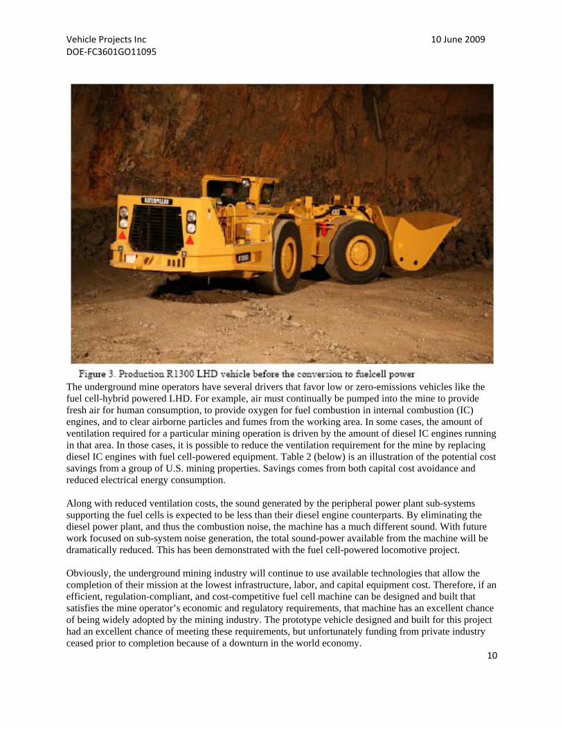
Figure 3: Production R1300 LHD vehicle before the conversion to fuel cell power ................................ 10
Figure 4: Reno, Nevada electrolysis of water into hydrogen demonstration ......................................... 11
Figure 5: R1300 truck load duty cycle .................................................................................................. 12
Figure 6: Fuel cell power plant module ................................................................................................ 17
Figure 7: Covered fuel cell power plant module .................................................................................. 17
Figure 8: Fuel cell power plant in situ with storage modules ................................................................ 18
Figure 9: Fuel cell power plant in situ with storage modules ................................................................ 18
Figure 10: Weight results of the total vehicle with the fuel cell power plant and hydrogen storage on
board ................................................................................................................................................. 18
Figure 11: Metal hydrides have high volumetric storage density, long dormancy, reversible operation for
very pure hydrogen and low storage pressure. .................................................................................... 19
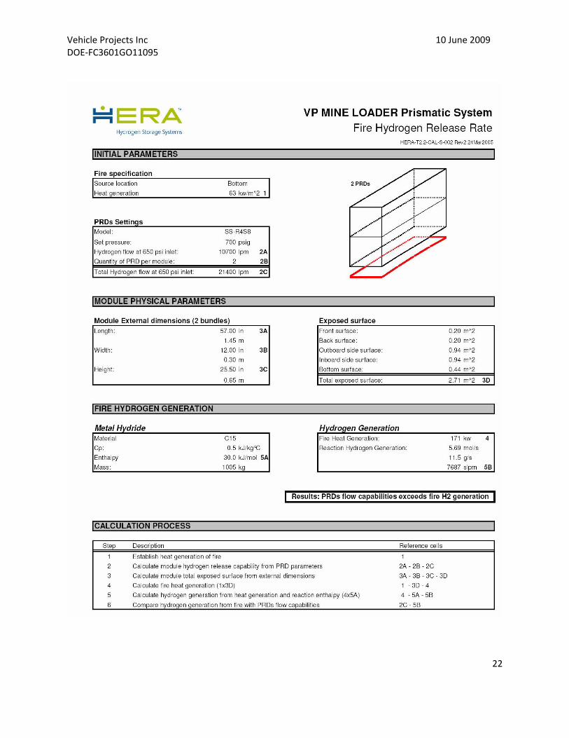
Figure 12: PRD hydrogen release and fire hydrogen release fate ..................................................... 21‐22
Figure 13: Metal‐hydride module schematic........................................................................................ 23
Figure 14: Propulsion system for the production R1300 LHD ................................................................ 24
Figure 15: Baseline performance characteristic of the R1300 ............................................................... 24
Figure 16: Common motor configurations ........................................................................................... 25
Figure 17: Electric motor placement options considered for the R1300 LHD ......................................... 26
Figure 18: Two‐motor variation of the forward drop box option .......................................................... 27
Figure 19: DRS PA44 Motor ................................................................................................................. 27
Figure 20: Final power‐train configuration .......................................................................................... 30
Figure 21: Detail of the motor‐planetary and rear pinion vehicle area .................................................. 31
Figure 22: DRS PA44 motor, Saminco motor controller and motor contactor box ................................. 32
Figure 23: Performance test on the propulsion system ........................................................................ 33
Figure 24: R1300 pedal configuration .................................................................................................. 34
Figure 25: Details of the conventional braking system ......................................................................... 36
Figure 26: Parallel mechanical and electrical braking data ................................................................... 37
Vehicle Projects Inc 10 June 2009 DOE‐FC3601GO11095
5
Figure 27: Series mechanical and electrical brake data ........................................................................ 38
Figure 28: LHD cooling systems ........................................................................................................... 41
Figure 29: Motor, fan, shroud, mounting structure and cooler assembly .............................................. 42
Figure 30: Screenshot of design software used to size the heat exchangers ......................................... 43
Figure 31: Coolant pump and motor schematic and flow chart ............................................................ 44
Figure 32: Motor controller ................................................................................................................ 44
Figure 33: Fan specifications and configuration ................................................................................... 45
Figure 34: Fan motor .......................................................................................................................... 45
Figure 35: Pressure drop and torque speed curve ................................................................................ 45
Figure 36: Pro/E drawing of the stack and electronics coolers .............................................................. 46
Figure 37: Control logic for the LHD Loader ......................................................................................... 47
Figure 38: dSpace screenshot of drive command temperatures and real time data plots ...................... 49
Figure 39: Flow chart used to determine control sequence .................................................................. 50
Figure 40: Failure mode analysis from a control strategy approach ...................................................... 50
Figure 41: RKI hydrogen detection system installed in the loader cab. .................................................. 51
Figure 42: Typical hydrogen detection and action chart ....................................................................... 52
Figure 43: An example of the operator display screen ......................................................................... 53
Table 1: Participating partner list .......................................................................................................... 9
Table 2: Summary of ventilation costs by mine location ....................................................................... 11
Table 3: Performance requirements of loader metal‐hydride storage [Miller et al 2006] ....................... 19
Table 4: Comparison table for two motor options ............................................................................... 28
Table 5: Specifications for the DRS PA44 permanent magnet brushless motor ..................................... 29
Table 6: Stack and electronics cooler specifications ............................................................................. 45
Vehicle Projects Inc 10 June 2009 DOE‐FC3601GO11095
6
Executive Summary
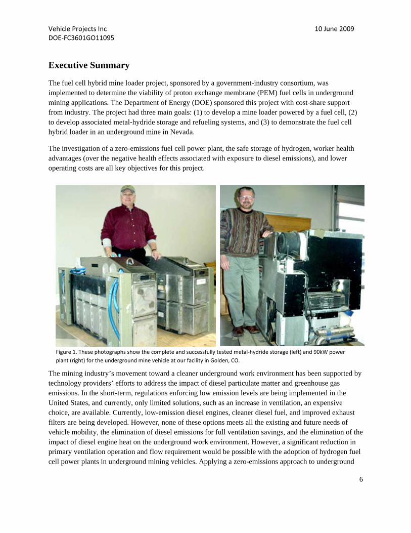
The fuel cell hybrid mine loader project, sponsored by a government-industry consortium, was implemented to determine the viability of proton exchange membrane (PEM) fuel cells in underground mining applications. The Department of Energy (DOE) sponsored this project with cost-share support from industry. The project had three main goals: (1) to develop a mine loader powered by a fuel cell, (2) to develop associated metal-hydride storage and refueling systems, and (3) to demonstrate the fuel cell hybrid loader in an underground mine in Nevada.
The investigation of a zero-emissions fuel cell power plant, the safe storage of hydrogen, worker health advantages (over the negative health effects associated with exposure to diesel emissions), and lower operating costs are all key objectives for this project.
The mining industry’s movement toward a cleaner underground work environment has been supported by technology providers’ efforts to address the impact of diesel particulate matter and greenhouse gas emissions. In the short-term, regulations enforcing low emission levels are being implemented in the United States, and currently, only limited solutions, such as an increase in ventilation, an expensive choice, are available. Currently, low-emission diesel engines, cleaner diesel fuel, and improved exhaust filters are being developed. However, none of these options meets all the existing and future needs of vehicle mobility, the elimination of diesel emissions for full ventilation savings, and the elimination of the impact of diesel engine heat on the underground work environment. However, a significant reduction in primary ventilation operation and flow requirement would be possible with the adoption of hydrogen fuel cell power plants in underground mining vehicles. Applying a zero-emissions approach to underground
Figure 1. These photographs show the complete and successfully tested metal‐hydride storage (left) and 90kW power
plant (right) for the underground mine vehicle at our facility in Golden, CO.
Vehicle Projects Inc 10 June 2009 DOE‐FC3601GO11095
7
mining vehicles will lead to clear advantages and no significant changes in the manner in which underground production is carried out.
Ventilation cost savings contribute to lower operating costs for fuel cell power versus diesel power. At the present time, however, these savings are not sufficient to offset the higher capital cost of fuel cells versus diesel power. The fuel cell manufacturing industry is working to reduce the product cost by automating many of the production steps while still advancing the technology, and consequently, the steady decrease in the purchase price for fuel cells is expected to lead to an equivalent cost crossover point for both power systems in the future.
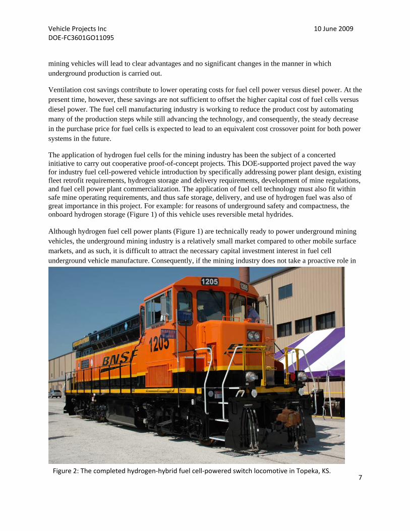
The application of hydrogen fuel cells for the mining industry has been the subject of a concerted initiative to carry out cooperative proof-of-concept projects. This DOE-supported project paved the way for industry fuel cell-powered vehicle introduction by specifically addressing power plant design, existing fleet retrofit requirements, hydrogen storage and delivery requirements, development of mine regulations, and fuel cell power plant commercialization. The application of fuel cell technology must also fit within safe mine operating requirements, and thus safe storage, delivery, and use of hydrogen fuel was also of great importance in this project. For example: for reasons of underground safety and compactness, the onboard hydrogen storage (Figure 1) of this vehicle uses reversible metal hydrides. Although hydrogen fuel cell power plants (Figure 1) are technically ready to power underground mining vehicles, the underground mining industry is a relatively small market compared to other mobile surface markets, and as such, it is difficult to attract the necessary capital investment interest in fuel cell underground vehicle manufacture. Consequently, if the mining industry does not take a proactive role in
Figure 2: The completed hydrogen‐hybrid fuel cell‐powered switch locomotive in Topeka, KS.

Vehicle Projects Inc 10 June 2009 DOE‐FC3601GO11095
8
developing this niche market and facilitating commercialization by fuel cell manufacturers, the underground mining vehicle market will remain behind the surface markets.
1.) Introduction
Hydrogen fuel cells are a well-known and broadly applied power technology. Chosen for their reliability, safety, and high power density, fuel cells have provided electric power to vehicles (space missions, city buses, submarines, locomotives) and power plant applications (home and network). In fact, all major automakers have advanced fuel cell projects.
The mining industry has always been willing to apply technology to solve health and safety, productivity, and operational efficiency issues, and currently, the mining industry is motivated to consider alternative power systems for the conventional diesel internal combustion engine. Of primary concern are critical issues such as worker health and operating cost reductions.
The quality of underground mine air must be controlled, especially in the light of stricter regulatory standards with respect to diesel particulate matter (PM). The recognition that PM is a carcinogenic is of concern to all industry stakeholders, but nevertheless, metal mines are now highly mechanized and predominantly use diesel in primary ore handling. Fuel cells produce no harmful emissions and only generate electricity and water and thus offer a viable alternative to improve the underground work environment.
However, there is very little motivation for the major engine suppliers to dramatically improve engine technology given the relatively small engine market that underground mining represents. Therefore, the current alternatives to make diesel power cleaner are limited to exhaust filters and cleaner diesel fuel, and in some instances, electrical power plant systems with cumbersome trailing cable are used instead of diesel. None of these options meets all the existing needs let alone the future needs of vehicle mobility, elimination of diesel emissions for full ventilation savings, and the impact of diesel engine heat on the underground work environment. Conventional power technologies are not simultaneously clean, safe, and productive.
Alternatively, the prototype vehicle uses an electric traction motor as its main motive power allowing additional energy savings through regenerative braking. A hydraulics system separately powered from the traction motor will improve vehicle performance and consequently productivity.
As with any industry, before the underground mining industry can utilize a new technology, such as an energy system for mobile equipment, a range of operational aspects must be considered as part of a “change management” approach that would include: health and safety risks, regulatory issues, system fit with the mining process, technical risks, and operating and capital costs. Mining companies have shown on numerous occasions that they are willing to support the development of alternative energy systems once all risks have been reduced to acceptable levels. Consequently, the results of a completed project will contribute to an understanding of all of the issues and thus an earlier adoption of these new technologies.
Vehicle Projects Inc 10 June 2009 DOE‐FC3601GO11095
9
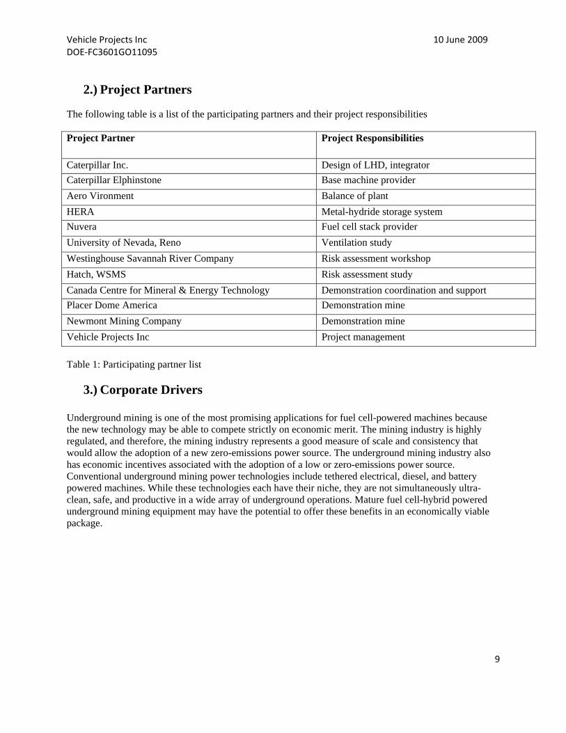
2.) Project Partners
The following table is a list of the participating partners and their project responsibilities Project Partner Project Responsibilities
Caterpillar Inc. Design of LHD, integrator
Caterpillar Elphinstone Base machine provider
Aero Vironment Balance of plant
HERA Metal-hydride storage system
Nuvera Fuel cell stack provider
University of Nevada, Reno Ventilation study
Westinghouse Savannah River Company Risk assessment workshop
Hatch, WSMS Risk assessment study
Canada Centre for Mineral & Energy Technology Demonstration coordination and support
Placer Dome America Demonstration mine
Newmont Mining Company Demonstration mine
Vehicle Projects Inc Project management
Table 1: Participating partner list
3.) Corporate Drivers Underground mining is one of the most promising applications for fuel cell-powered machines because the new technology may be able to compete strictly on economic merit. The mining industry is highly regulated, and therefore, the mining industry represents a good measure of scale and consistency that would allow the adoption of a new zero-emissions power source. The underground mining industry also has economic incentives associated with the adoption of a low or zero-emissions power source. Conventional underground mining power technologies include tethered electrical, diesel, and battery powered machines. While these technologies each have their niche, they are not simultaneously ultra-clean, safe, and productive in a wide array of underground operations. Mature fuel cell-hybrid powered underground mining equipment may have the potential to offer these benefits in an economically viable package.
Vehicle Projects Inc 10 June 2009 DOE‐FC3601GO11095
10
The underground mine operators have several drivers that favor low or zero-emissions vehicles like the fuel cell-hybrid powered LHD. For example, air must continually be pumped into the mine to provide fresh air for human consumption, to provide oxygen for fuel combustion in internal combustion (IC) engines, and to clear airborne particles and fumes from the working area. In some cases, the amount of ventilation required for a particular mining operation is driven by the amount of diesel IC engines running in that area. In those cases, it is possible to reduce the ventilation requirement for the mine by replacing diesel IC engines with fuel cell-powered equipment. Table 2 (below) is an illustration of the potential cost savings from a group of U.S. mining properties. Savings comes from both capital cost avoidance and reduced electrical energy consumption. Along with reduced ventilation costs, the sound generated by the peripheral power plant sub-systems supporting the fuel cells is expected to be less than their diesel engine counterparts. By eliminating the diesel power plant, and thus the combustion noise, the machine has a much different sound. With future work focused on sub-system noise generation, the total sound-power available from the machine will be dramatically reduced. This has been demonstrated with the fuel cell-powered locomotive project. Obviously, the underground mining industry will continue to use available technologies that allow the completion of their mission at the lowest infrastructure, labor, and capital equipment cost. Therefore, if an efficient, regulation-compliant, and cost-competitive fuel cell machine can be designed and built that satisfies the mine operator’s economic and regulatory requirements, that machine has an excellent chance of being widely adopted by the mining industry. The prototype vehicle designed and built for this project had an excellent chance of meeting these requirements, but unfortunately funding from private industry ceased prior to completion because of a downturn in the world economy.
Vehicle Projects Inc 10 June 2009 DOE‐FC3601GO11095
11
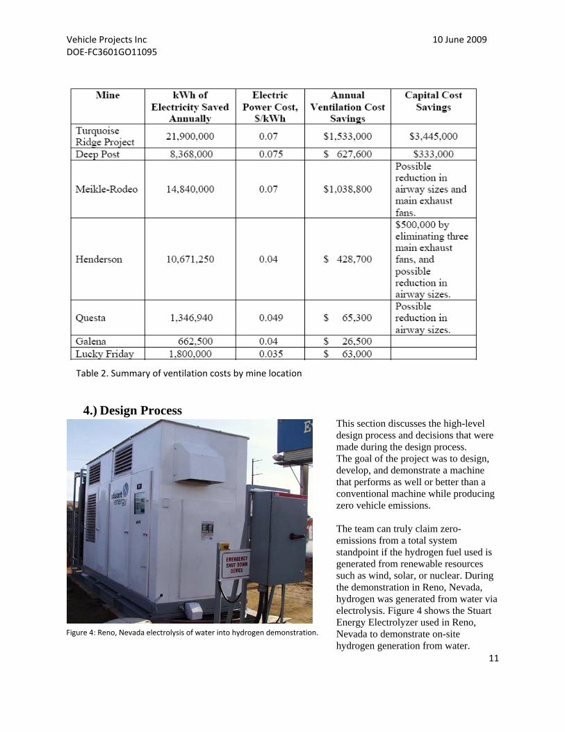
4.) Design Process This section discusses the high-level design process and decisions that were made during the design process. The goal of the project was to design, develop, and demonstrate a machine that performs as well or better than a conventional machine while producing zero vehicle emissions. The team can truly claim zero-emissions from a total system standpoint if the hydrogen fuel used is generated from renewable resources such as wind, solar, or nuclear. During the demonstration in Reno, Nevada, hydrogen was generated from water via electrolysis. Figure 4 shows the Stuart Energy Electrolyzer used in Reno, Nevada to demonstrate on-site hydrogen generation from water.
Figure 4: Reno, Nevada electrolysis of water into hydrogen demonstration.
Table 2. Summary of ventilation costs by mine location

Vehicle Projects Inc 10 June 2009 DOE‐FC3601GO11095
12
This section reviews the process by which the high-level machine architecture was established and the selection of the types of systems that make up the LHD machine. The result is an earthmoving machine with improved efficiency and significant, albeit in this machine, complicated, technical advancements. The first goal when designing any machine system is to define the performance specifications the machine is expected to meet. In this case, the critical power requirement is that the continuous rating of the prime mover equals or exceeds the mean power of the vehicle’s duty cycle (see Figure 5). Mathematical analysis of the duty cycles demonstrates that the original loader diesel engine, which supplies power to both the drive train and the hydraulics, is rated at 165 hp (123 kW). The PA-44 motor is rated at 450 hp (335 kW) and was used strictly for traction power (a separate UQM BPM motor supplied power to the hydraulics). AeroVironment limited the current to the traction motor thus restricting power to the vehicle within acceptable limits. Because an existing commercial loader was modified, the existing machine provided the duty cycle, or benchmark, to which the fuel cell-powered machine was compared. To quantify the performance of the standard R1300 diesel-powered machine, a series of baseline machine performance tests were run at Caterpillar’s Peoria Proving Ground. The tests quantified the loader’s performance using standardized tests and operations. The original plan was to repeat the same set of tests with the fuel cell-powered machine thus generating a direct comparison of performance. Typical underground operation duty cycles were gathered for the LHD. To establish this baseline, the Caterpillar team developed worst-case duty cycles that represented the energy required by the various sub-systems, such as power train and hydraulic systems, as the machine works in a load-and-carry cycle and a truck loading cycle. These representative duty cycles were derived from actual loader tests along
with the description of the geometry of the environments provided by the mining partners within which this machine would perform. This information was instrumental in the design of the machine because the duty cycle is the basis for the engineering analysis and project feasibility study. In the design process, the duty cycle drives the energy usage specifications by all machine systems, thus determining the performance required of all major systems and sub-systems. The duty cycle directly drives requirements for power train and hydraulic systems, while the power demands in these principal systems drive the load for the cooling system and the fuel cell power module. Once the requirements and specifications of the system were established, the high-level machine configuration was generated. The choice for the type of fuel cell for the power plant was the Proton Exchange Membrane, or PEM, fuel cell. This particular type of fuel cell has been the object of considerable research activity. It is used often for light-duty mobile applications like automobiles. There are a number of commercial entities manufacturing PEM’s today, which makes this fuel cell more available than other types. Three leading ways of storing hydrogen fuel are as cryogenic liquid in cylinders, as compressed gas in cylinders, or as
Figure 5: R1300 truck load duty cycle.

Vehicle Projects Inc 10 June 2009 DOE‐FC3601GO11095
13
metal hydride in storage tanks. The metal-hydride storage system (Figure 1) was selected as the fuel storage system for the LHD, primarily because of its safety characteristics due to operation at low pressure and thermal stability. In the event of a system rupture, the hydrogen will be released slowly rather than rapidly, as in the case of some failure modes of a compressed hydrogen system. Power generated by PEM fuel cells is electrical, and thus the design team redesigned the LHD machine to be completely electrically powered. Some competitive LHD manufacturers convert LHDs to electrical power, and typically these conversions require replacement of the diesel engine with a large electric motor connected to a power system via a tether cable. The single motor was unacceptable in the case of the fuel cell-powered LHD because of space constraints and the volume of fuel, and thus the size of the storage system, required. The design team recognized early on that it would be imperative to maximize LHD efficiency in order to reduce the required fuel storage and overall weight of the machine. Consequently, the drive train and the hydraulic systems were redesigned to maximize efficiency while reducing the physical size of these systems wherever possible. In addition, the LHD was designed as a hybrid machine to allow for regenerative braking and to also perform load leveling functions for the fuel cell power plant. This strategy accomplished two things: it helped minimize the size of the PEM fuel cell array and power plant and allowed for a more efficient use of the hydrogen fuel by the system.
5.) Design Results The fuel cell-powered LHD was originally designed to perform at the same level as the diesel-powered loader. However, the higher peak power available from the LHD offers power bursts for short durations, thus allowing the machine to perform strong in areas like loading where both the hydraulics and power train are active. The machine will be able to accelerate and climb short grades with good performance. One deficiency encountered was in the area of fuel capacity. In order to package the machine in roughly the same envelope and keep the weight gain to a minimum, the capacity of the fuel storage was reduced below the original design level. The original design goal dictated an eight hour shift; however, fuel capacity was reduced as weight of the storage system increased. Under the worst-case conditions, 4-5 continuous hours of maximum machine performance are calculated. The results will depend on the level of energy regeneration and on the characteristics of the actual duty cycle. Although the design goal was to minimize vehicle weight gain, the actual weight gain was significant with possible impact on machine performance.
6.) Development Results Several team performance-tuning sessions were held at the Caterpillar Tucson Proving Grounds in 2007 and 2008. Below is a list of some of the 2008 actions undertaken in an attempt to get the machine operational and then prepared for performance testing. July 2008 Highlights
Completed hydro test of hydrogen system lines. Found and repaired a leak in the RHS hydride storage bed.
Installed EMI filter on UQM hydraulic motor drive. Upon troubleshooting NIMH battery charge controls, found defective Smart-Guard circuit board
#3. System patch installed to bypass faulty module.

Vehicle Projects Inc 10 June 2009 DOE‐FC3601GO11095
14
August 2008 Highlights
Installed power module and initiated high voltage (HV) battery charge. The battery would not charge due to fault codes preventing the relays from closing. Fault code 128: Smart Guard module 21 is showing 20.1 volts. Upon troubleshooting NIMH battery charge controls, found defective Smart-Guard circuit board #21. Had AeroVironment contract work to create new patch software to override SG21.
Re-connected Navigator display and found system issues. Installed new patch software. Battery faults cleared and HV relays now operational.
Coolant pumps, fan, and hydraulic motors operational via D-space control desk.
September 2008 Highlights
Installed new Smart Guard circuit boards. Battery verified good. Operational status of hydraulic pump motor (EMI filter) verified good. Able to operate hydraulics
with fuel cell power for 30 minutes. System noise measurements taken for all electric motors except propulsion. Fuel cell operational check good; able to charge HV battery. Propulsion motor not operational—faults and noise. Corrected a wiring issue on the control
connector but still not able to run propulsion motor. Team consensus that the propulsion motor will need an EMI filter similar to the one installed on the hydraulic motor (but much larger), and additional work on the Dspace interface was necessary to successfully move the vehicle. It was determined that neither VP nor Cat had the budget in place to support the design and procurement of the EMI filter and additional work on Dspace.
The team was successful in getting the machine and implements to operate under battery power by disabling the system safety interlocks, which also allowed operation of the implement hydraulics during fuel cell operation. Though the fuel cell power plant worked very well, system electronic noise continued to be a problem along with dual system communication, which prevented full machine operation during fuel cell operation. It has been concluded that additional development would be required to get the complete machine fully operational.
7.) Conclusions With current technology, PEM fuel cells are produced in high volume and are becoming less expensive while providing greater integrity and longevity. Pure hydrogen is provided to industrial customers in southern California for around $2 a kilogram (1 gallon of diesel energy equivalency). Hydrogen at present is supplied from a pipeline. The US average per gallon of diesel fuel is $2.60 (12 Oct 2009 EIA). This is the present cost of diesel without adding the entire associated social, subsidy, and security costs to the fuel. It has been suggested that the true cost of diesel fuel is $10-15 dollars per gallon (International Centre for Technology Assessment 2009). Hydrogen fuel stations are now in operation in a number of locations in the US and the world that resembles the filling stations used by passenger car customers today. Batteries are becoming more advanced, with new technology and materials making battery power more dense and compact. Distribution, carbon cycle-free manufacturing, and storage of hydrogen remain behind the development of the rest of the technology, but these elements in the fuel cell technology equation are presently being researched by both government and industry.

Vehicle Projects Inc 10 June 2009 DOE‐FC3601GO11095
15
The technology used in the LHD loader is now five years old, and that technology certainly could be utilized in a fuel cell project today with some modification to bring it up to present standards. However, other factors hinder development of a fuel cell loader. In addition to the onboard fuel capacity and the mine hydrogen infrastructure, the method of transporting hydrogen into the mine will be an issue. For the purposes of the demonstration LHD, we planned to remove the fuel storage from the machine and transfer the storage module to the surface for refueling. The mining industry partner indicated that this practice might be difficult to adopt at production mine sites. A better method of safely supplying hydrogen underground needs to be developed. Also, many of the systems on the machine have increased complexity and design compromises, giving rise to the possibility of greater maintenance and reliability issues. For instance, to obtain the type of thermal management needed by the LHD, a very complex high-performance cooling system was designed. As a result, the ambient capability of the machine may not be as broad as the diesel counterpart. Plugging will be a concern due to greater fin density on the heat exchangers. Overall reliability will be determined by operating the vehicle while tracking system and component failure modes and repair costs. The PEM fuel cell manufacturer has newer generation fuel cells in the marketplace that can produce higher power levels while utilizing less space. The NiMH battery has now been superseded by Lithium Ion technology. The two control systems on the vehicle proved complicated and difficult to interface, and consolidation into one supervisory control for the entire vehicle during the first stages of the project would have been preferable. The benefits these technologies promise will require more development on the part of fuel cell manufacturers, the government, and OEM companies like Caterpillar. Subsequent chapters in the design section review the process of designing various machine systems that utilize the electrical power for propulsion, hydraulics, and cooling, as well as other required machine systems like the control system.
Vehicle Projects Inc 10 June 2009 DOE‐FC3601GO11095
16
Design Review
1.) Fuel Cell Power Plant Design Overview 2.) Metal-Hydride Hydrogen Storage Module Overview 3.) Propulsion System Design Overview
4.) Hydraulic System Design Overview
5.) Cooling System Design Overview
6.) Control System Design Overview
7.) Testing Results

Vehicle Projects Inc 10 June 2009 DOE‐FC3601GO11095
17
1.) Fuel Cell Power Plant Design Overview The power plant module is designed as a fuel cell/battery hybrid as shown in Figures 6 and 7. The module consists of 3 PEM fuel cell stacks, rated at 290V, 300A, 87 kW gross output power, along with 108 Nickel Metal-Hydride (NiMH) batteries capable of an additional 75 kW for about 5 minutes. Peak power is about 140 kW net for short durations, such as loading the bucket with ore or tramming up an incline. Regenerative braking is included and utilized to recover energy.
There are 3 voltage busses in the system: 1) a high voltage bus (600-850 VDC) that powers the traction motor and hydraulic motor inverter; 2) a medium voltage bus (280-400 VDC), powered by the fuel cells, that powers the air compressor, cooling pumps, and the cooling fan; and 3) a 24 VDC bus for auxiliaries and startup. Included in the fuel cell power module is a system controller that will monitor power, temperature, pressures, and flow rates; an 80 kW DC/DC boost converter (medium to high voltage); an 8 kW bi-directional DC/DC power module capable of handling 24V to 400V; and a data acquisition system that will monitor every cell of the 402 total cells of the fuel cell stacks.
The air compressor is a centrifugal supercharger design rotating at 150,000 rpm and delivering nearly 4,700 SLM at 1.7 bara. The fuel cell stacks are cooled with DI water flowing at 150 LPM to maintain the stack temperature between 65C and 70C. The DI cooling loop interfaces with the metal-hydride storage to supply the necessary heat to desorb the hydrogen from the metal hydride.
Figure 8 (below) shows the overall integration of the fuel cell-powered loader. The fuel cell power plant module is located between the two metal-hydride storage modules, forming a saddlebag configuration. The metal-hydride storage modules (Figures 8 and 9) are removable so that, when in use in shaft mines, the metal-hydride modules can be transported to the surface for refueling. Another major addition is the traction motor (discussed later in detail), which is situated in front of the fuel cell power plant module, a
Figures 6 and 7: Fuel cell power plant module uncovered and covered.


Vehicle Projects Inc 10 June 2009 DOE‐FC3601GO11095
19
Sufficient capacity for more than one work shift for stationary application Refueling underground Rapid refueling (timeframe consistent with conventional diesel vehicle refueling) Refueling by the vehicle operator during production work, and Storage medium will not be so heavy as to exceed total vehicle weight limitations and to maximize
the efficiency of the vehicle (payload relative to empty vehicle weight) The metal-hydride storage was required to meet the following performance specifications in Table 3.
Capacity Hydrogen storage capacity of 14kg for operation of approximately one shift.
Hydrogen Flow Full-power hydrogen flow of 840L/min at 3.1 bar. Half-power hydrogen flow of
420L/min at 1.9 bar.
Maximum Pressure Hydrogen pressure limited to 7.8 bar during vehicle operation in a mine.
Refueling Heat transfer kinetics that allow refueling in less than 30 minutes. Metal-hydride
system is capable of being refueled in situ or off the vehicle.
Layout Storage system with low profile so it does not interfere with operator visibility.
Mechanical The system must withstand shock and vibration associated with mine loader
service.
Table 3: Performance requirements of loader metal-hydride storage [Miller et al 2006]
The HERA metal-hydride storage system (Figure 11) can be refueled in 15 minutes, which we believe is a record for large metal-hydride storage systems. Safety of the metal-hydride system has also been increased by reducing the pyrophoricity of the metal hydride. The tradeoff for the fast refueling rate is complexity of the heat exchanger, and the tradeoff for reduced pyrophoricity of the metal hydride is somewhat lower hydrogen density than originally specified.
Few options currently being researched show promise of the kind of storage flexibility provided by metal hydrides. Compressed hydrogen, another proven and extensively tested storage option, is
Figure 11: Metal hydrides have high volumetric storage density, long dormancy, reversible operation for very pure hydrogen, and low storage pressure.

Vehicle Projects Inc 10 June 2009 DOE‐FC3601GO11095
20
restricted to the volume of hydrogen that can be stored and suffers from negative consequence anticipation.
The 14 kg of hydrogen are stored in four separate canisters. Waste heat from the fuel cells desorbs the hydrogen from the metal hydride for use by the fuel cells. Since the fuel cell/battery hybrid loader was to be demonstrated underground (which was not achieved) in restricted environments, the amount of heat provided to the metal hydride was closely controlled to minimize the pressure in the canisters and ultimately the amount of free hydrogen in the system. Cooling fluid transfers fuel cell and battery waste heat to the metal-hydride heat exchangers to release hydrogen for power production and to remove heat. The heat absorbed by the storage system reduces the heat load on the vehicle’s excess heat radiator.

Vehicle Projects Inc 10 June 2009 DOE‐FC3601GO11095
21
Vehicle Projects Inc 10 June 2009 DOE‐FC3601GO11095
22

Vehicle Projects Inc 10 June 2009 DOE‐FC3601GO11095
23
Vehicle Projects Inc 10 June 2009 DOE‐FC3601GO11095
24
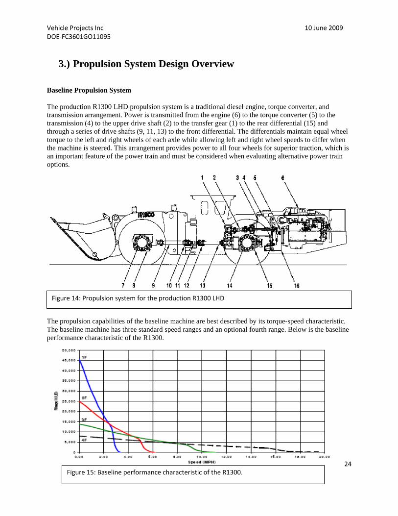
3.) Propulsion System Design Overview Baseline Propulsion System The production R1300 LHD propulsion system is a traditional diesel engine, torque converter, and transmission arrangement. Power is transmitted from the engine (6) to the torque converter (5) to the transmission (4) to the upper drive shaft (2) to the transfer gear (1) to the rear differential (15) and through a series of drive shafts (9, 11, 13) to the front differential. The differentials maintain equal wheel torque to the left and right wheels of each axle while allowing left and right wheel speeds to differ when the machine is steered. This arrangement provides power to all four wheels for superior traction, which is an important feature of the power train and must be considered when evaluating alternative power train options.
The propulsion capabilities of the baseline machine are best described by its torque-speed characteristic. The baseline machine has three standard speed ranges and an optional fourth range. Below is the baseline performance characteristic of the R1300.
Figure 14: Propulsion system for the production R1300 LHD
Figure 15: Baseline performance characteristic of the R1300.


Vehicle Projects Inc 10 June 2009 DOE‐FC3601GO11095
26
However, individual wheels may demand 50% of the propulsion torque/power, which means that each of the four wheel motors must provide roughly half the capability of the single drive-point option above. After selecting the single-point drive option for its obvious advantages, several different implementations were examined. Each was evaluated for its performance capability, complexity, and ability to be packaged within the available machine space. Below is a diagram showing several electric motor placement options.
Forward Drop Box: This option was not feasible given the size of the propulsion motor—it interferes with the machine’s frame articulation (steering) structural components. The mass of the motor is also too much to cantilever off of the drop box. Additionally, the drop box and motor experience lateral motion as the axle oscillates, requiring additional space for clearance. Centerline: This option eliminates the drop box and lowers the center of gravity (good for stability). However, this would require speed reduction gears on each end of the motor and a very short drive shaft between the front of the motor/reduction gears and the center drive shaft. This short length could result in insufficient universal joint life. Aft Drop Box: This option requires the least redesign and modification as it is the most similar to the conventional R1300 mechanical transmission arrangement. However, this location would interfere with the fuel cell power module envelope. Aft In-Line: This option eliminates the drop box and lowers the center of gravity. This configuration requires that the rear differential be converted to a through-drive configuration, and the belly pan may also need modifications. Bevel gear stress is increased due to the through-drive but shouldn’t be a problem for the demo machine. This is the preferred configuration to meet packaging and other requirements.
Figure 17: Electric motor placement options considered for the R1300
LHD.

Vehicle Projects Inc 10 June 2009 DOE‐FC3601GO11095
27
Below is a two-motor variation on the forward drop box option. While this option addresses the articulation frame interference, axle oscillation motion is still an issue, which requires clearance space and places the motors higher, raising the center of gravity.
Figure 18: Two‐motor variation of the forward drop box option.
Figure 19: DRS PA44 motor.

Vehicle Projects Inc 10 June 2009 DOE‐FC3601GO11095
28
Propulsion Motor Selection Following is a table comparing two identified motor options. While both motor options claim characteristics that could meet the baseline performance requirements, the Kaman has a more attractive aspect ratio for packaging and is lighter. Weight was a concern because the concept machine was approaching the maximum weight capacity of the tires. Subsequent to this analysis, DRS Technologies purchased Kaman and this specific motor was discontinued. A DRS PA44 motor (Figure 19, above) with similar physical and performance characteristics (Table 5, below) was selected as a replacement for the Kaman motor.
Table 4: Comparison table for two motor options

Vehicle Projects Inc 10 June 2009 DOE‐FC3601GO11095
29
Propulsion Motor Performance Following is a graph showing the performance of the electric propulsion motor relative to the baseline R1300 capability. The R1300 rim pull-speed data was converted to torque and speed at the motor for easier comparison. It can be observed that the electric option is capable of providing slightly more torque than the baseline at low speed in 1st gear and nearly the same top speed capability as the baseline R1300 in 3rd gear. It can also be observed that the electric motor is capable of providing significantly more torque than the baseline machine through the majority of the operating range. Some higher torque/power capability may be necessary to offset weight increases for the concept machine.
If packaging concerns weren't a critical issue for the concept machine and space were available for a two-range transmission, the motor could be downsized considerably and still provide the maximum low speed torque required for loading material in first gear and also the maximum speed capability associated with the optional 4th speed range.
Table 5: Specifications for the DRS PA44 permanent magnet brushless motor

Vehicle Projects Inc 10 June 2009 DOE‐FC3601GO11095
31
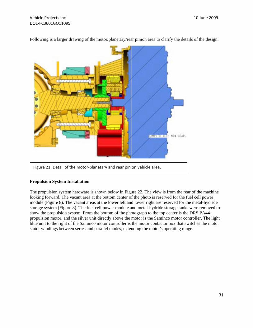
Following is a larger drawing of the motor/planetary/rear pinion area to clarify the details of the design.
Propulsion System Installation The propulsion system hardware is shown below in Figure 22. The view is from the rear of the machine looking forward. The vacant area at the bottom center of the photo is reserved for the fuel cell power module (Figure 8). The vacant areas at the lower left and lower right are reserved for the metal-hydride storage system (Figure 8). The fuel cell power module and metal-hydride storage tanks were removed to show the propulsion system. From the bottom of the photograph to the top center is the DRS PA44 propulsion motor, and the silver unit directly above the motor is the Saminco motor controller. The light blue unit to the right of the Saminco motor controller is the motor contactor box that switches the motor stator windings between series and parallel modes, extending the motor's operating range.
Figure 21: Detail of the motor‐planetary and rear pinion vehicle area.

Vehicle Projects Inc 10 June 2009 DOE‐FC3601GO11095
32
Figure 22: DRS PA44 motor, Saminco motor controller and motor contactor box

Vehicle Projects Inc 10 June 2009 DOE‐FC3601GO11095
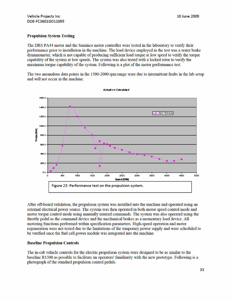
34
There are three pedals in the baseline R1300. The far left boot-shaped plate is a static a footrest. The larger black pedal to the far right is the throttle pedal, which controls engine speed in the baseline R1300. Much like a traditional accelerator pedal in a passenger vehicle, increased pedal depression commands increase engine speed, which in turn produces more thrust, higher acceleration, and higher travel speed. The center pedal (marked with an X in the photo) is the brake pedal. Depressing the brake pedal increases the pressure in the hydraulic brake system in proportion to the amount of pedal force applied by the operator, also much like the brake pedal in a passenger vehicle. The leftmost pedal is the neutralizer/brake pedal, which simultaneously places the transmission in neutral and applies the brakes. This allows the operator to keep the throttle pedal depressed to maintain high loader linkage speeds while simultaneously eliminating propulsive power from the transmission and thus permitting braking. Prototype Operator Controls Propulsion: In the prototype fuel cell-powered machine, the throttle pedal controls the power demand from the propulsion motor. The propulsion controller has been programmed to simulate the gear ranges and propulsion characteristics of the conventional R1300. A slight throttle pedal actuation will command low power (low speed and low rim pull) similar to a conventional engine at low speed, and a large pedal actuation will command high power (high speed and high rim pull) like a conventional engine at high speed. A virtual gear range selected by the operator regulates the maximum rim pull and speed associated with any given throttle pedal actuation and therefore mimics the characteristics of the conventional machine. It was determined that vehicle operators would benefit from the ability to select virtual gears
Figure 24: R1300 pedal configuration.
Vehicle Projects Inc 10 June 2009 DOE‐FC3601GO11095
35
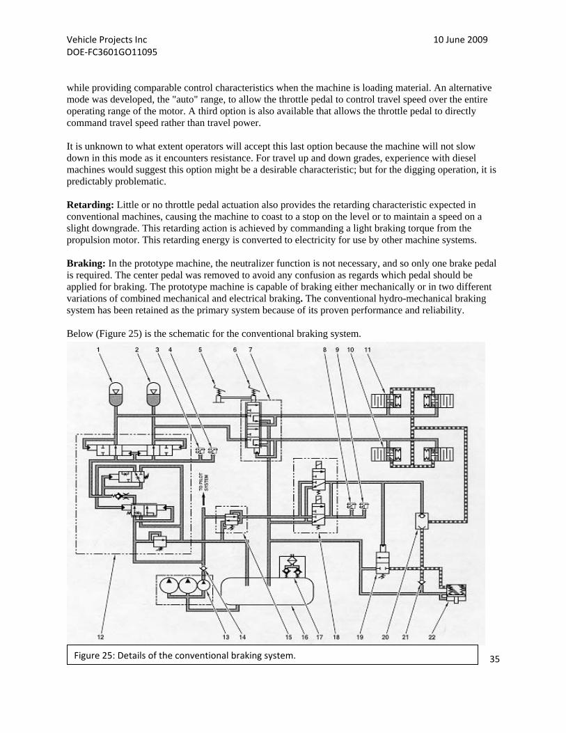
while providing comparable control characteristics when the machine is loading material. An alternative mode was developed, the "auto" range, to allow the throttle pedal to control travel speed over the entire operating range of the motor. A third option is also available that allows the throttle pedal to directly command travel speed rather than travel power. It is unknown to what extent operators will accept this last option because the machine will not slow down in this mode as it encounters resistance. For travel up and down grades, experience with diesel machines would suggest this option might be a desirable characteristic; but for the digging operation, it is predictably problematic. Retarding: Little or no throttle pedal actuation also provides the retarding characteristic expected in conventional machines, causing the machine to coast to a stop on the level or to maintain a speed on a slight downgrade. This retarding action is achieved by commanding a light braking torque from the propulsion motor. This retarding energy is converted to electricity for use by other machine systems. Braking: In the prototype machine, the neutralizer function is not necessary, and so only one brake pedal is required. The center pedal was removed to avoid any confusion as regards which pedal should be applied for braking. The prototype machine is capable of braking either mechanically or in two different variations of combined mechanical and electrical braking. The conventional hydro-mechanical braking system has been retained as the primary system because of its proven performance and reliability. Below (Figure 25) is the schematic for the conventional braking system.
Figure 25: Details of the conventional braking system.
Vehicle Projects Inc 10 June 2009 DOE‐FC3601GO11095
36
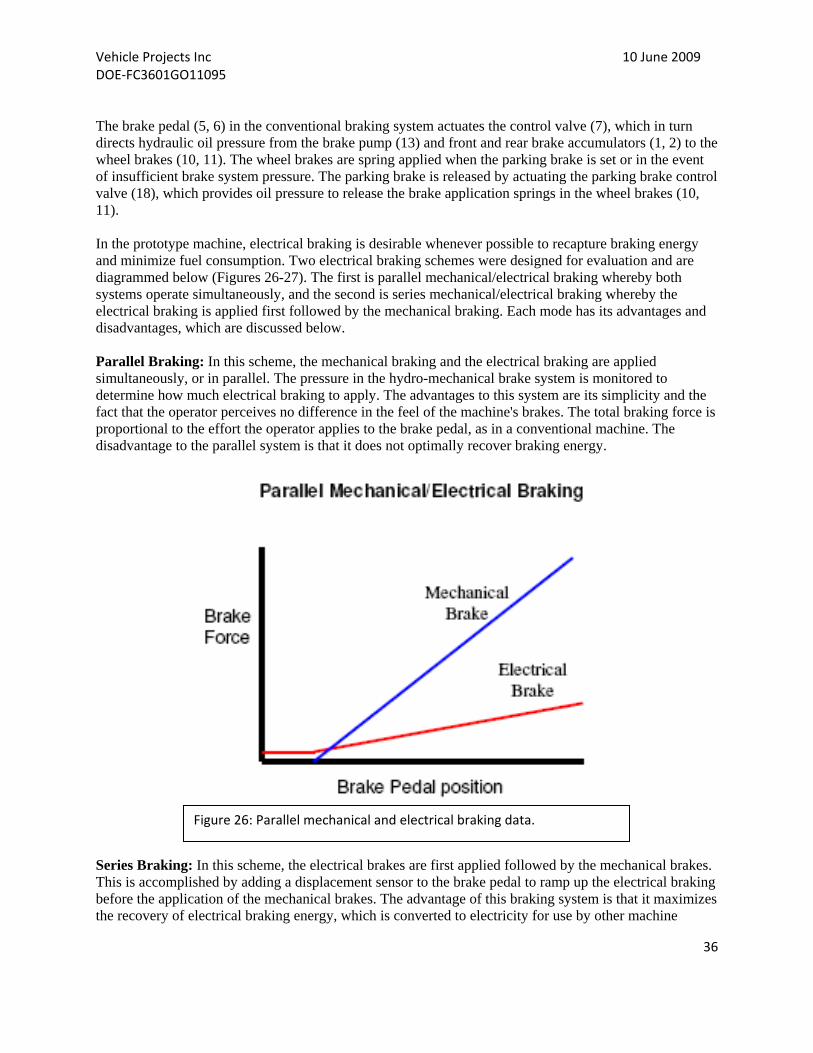
The brake pedal (5, 6) in the conventional braking system actuates the control valve (7), which in turn directs hydraulic oil pressure from the brake pump (13) and front and rear brake accumulators (1, 2) to the wheel brakes (10, 11). The wheel brakes are spring applied when the parking brake is set or in the event of insufficient brake system pressure. The parking brake is released by actuating the parking brake control valve (18), which provides oil pressure to release the brake application springs in the wheel brakes (10, 11). In the prototype machine, electrical braking is desirable whenever possible to recapture braking energy and minimize fuel consumption. Two electrical braking schemes were designed for evaluation and are diagrammed below (Figures 26-27). The first is parallel mechanical/electrical braking whereby both systems operate simultaneously, and the second is series mechanical/electrical braking whereby the electrical braking is applied first followed by the mechanical braking. Each mode has its advantages and disadvantages, which are discussed below. Parallel Braking: In this scheme, the mechanical braking and the electrical braking are applied simultaneously, or in parallel. The pressure in the hydro-mechanical brake system is monitored to determine how much electrical braking to apply. The advantages to this system are its simplicity and the fact that the operator perceives no difference in the feel of the machine's brakes. The total braking force is proportional to the effort the operator applies to the brake pedal, as in a conventional machine. The disadvantage to the parallel system is that it does not optimally recover braking energy.
Series Braking: In this scheme, the electrical brakes are first applied followed by the mechanical brakes. This is accomplished by adding a displacement sensor to the brake pedal to ramp up the electrical braking before the application of the mechanical brakes. The advantage of this braking system is that it maximizes the recovery of electrical braking energy, which is converted to electricity for use by other machine
Figure 26: Parallel mechanical and electrical braking data.

Vehicle Projects Inc 10 June 2009 DOE‐FC3601GO11095
37
systems, thereby saving fuel. The disadvantage is that the operator is using pedal position to control braking force in the electrical braking range rather than pedal effort, a departure from conventional vehicle brake system operation and thus operator acceptance of this system is unknown.
Resistor Grid The electric propulsion motor is used to retard or brake the machine, and thus the electrical energy generated must be routed somewhere on the vehicle. If the implement and steering system is in operation, the generated energy could be immediately consumed. If the battery is less than fully charged, the generated energy could be directed to the battery and stored for use when required later, but if the machine is neither operating at sufficient levels so the energy can be consumed or the battery is not depleted sufficiently so the energy can be stored, then there are two options: to cease generating the energy or to dissipate it. If the machine were to cease generating energy, there would be no electrical retarding or braking capability, which would result in inconsistent retarding and braking feel. Because this result could be objectionable to the operator, a liquid cooled resistor grid was included to dissipate the excess energy when there is no other use for it in the system. Safety Interlocks Safety interlocks have been built into the propulsion control system to prevent unexpected machine motion. The parking brakes are applied whenever there is insufficient hydraulic pressure to operate the service brakes, and the propulsion is disabled whenever the parking brake is applied. The propulsion is also disabled whenever steering is unavailable, either because the door is ajar, the steering lock lever is engaged, or the steering pump is inoperable. The propulsion system is also disabled in the event of various fault conditions (electrical, thermal, and communications). To enable propulsion, all disabling
Figure 27: Series mechanical and electrical brake data.

Vehicle Projects Inc 10 June 2009 DOE‐FC3601GO11095
38
indicators must be resolved, and then the operator must place the travel direction selector switch in neutral, then into either the forward or reverse position. This required action prevents unanticipated motion should the disabling indicators be cleared with the travel direction selector inadvertently left in forward or reverse. An override feature has been provided to permit machine movement in an emergency. Advantages of the Prototype Propulsion System The prototype propulsion system has several advantages over the conventional R1300 system. First and foremost is improved propulsion efficiency. Analysis indicates that a conventional torque converter and mechanical transmission power train average 50% efficiency through a typical loading cycle. The greatest inefficiency lies in the torque converter when operated near stall (e.g., high torque, low speed during digging operations). The efficiency of an electric propulsion system is around 70% for the same loading cycle. The second advantage is the ability to recapture retarding or braking energy and re-route it to other systems or to store it for later use. Analysis indicates that, on level ground loading cycles, this amount is roughly 5% of the work cycle energy. This number grows dramatically when operating on steep downgrades. Both of the above advantages result in reduced fuel consumption, which extends the operating time between fuel refills. The final advantage of system software programming is the ability to configure a broad range of parameters for the propulsion control. The machine could be programmed to operate gently for novice operators and aggressively for expert operators, or the machine could be programmed for different operating conditions (e.g., underground loading or travel above ground). Propulsion control could also be programmed to implement schemes to protect the machine and extend the life of various components (e.g., axle protection and tire slip prevention).
4.) Hydraulic System Design Overview LHD R1300FC Integrated LS Hydraulic System Background on the existing LHD R1300 mining wheel loader The existing hydraulic systems are made up of three separate systems and all share a common hydraulic tank: implement hydraulic system, steering hydraulic system, and the brake-pilot hydraulic system. The implement hydraulic system is open center tandem pilot-operated (joystick) fixed displacement. The steering hydraulic system is a closed center pilot-operated (joystick) fixed displacement. The brake-pilot hydraulic system is a closed center two-accumulator fixed displacement. R1300FC Hydraulic System Design Descriptions Overall hydraulic system configuration The prototype hydraulic system is made up of two systems that share a common hydraulic tank: implement steering-pilot hydraulic system and brake-pilot hydraulic system. The implement steering-pilot hydraulic system is LS system-closed center-parallel pilot operated (joystick) steering circuit and has priority over the implement-variable displ-pr. comp. (piston pump). The brake-pilot cooling drive hydraulic system is closed center dual-accumulator parallel fixed displacement (gear pump).

Vehicle Projects Inc 10 June 2009 DOE‐FC3601GO11095
39
Flow sharing (LUDV) hydraulic system advantage The flow sharing system demonstrates distinct advantages over a standard LS system, especially for wheel loader applications. During operation, there is constant simultaneous engagement of bucket, boom, and possibly auxiliary sections, which allows for simultaneous operations to be performed (i.e., lift and dump while truck loading, rack-back and lift during loading, etc. In a standard LS-System, when the pump flow is insufficient to satisfy all chosen actuators, the actuator with the highest pressure slows down or stops completely. In comparison, a flow sharing system would automatically reduce the flow for both actuators by the same percentage. Therefore, the machine operator does not have to pay attention to that part of the loading, which means less-experienced operators can use the machine. To accomplish this flow sharing function, the sectional pressure compensators reduce the actuator flows. The full pump flow is then shared between the boom and the bucket by 30% and 70%. All pump flow is utilized by the actuators and does not have to be throttled in the open center channel; therefore, the cycle time as well as material throughput is improved.
5.) Cooling System Design Overview Overview of Design Criteria and Schematics The conventional R1300 baseline machine with a diesel engine had the following cooling components:
Radiator: ethylene glycol circuit provides engine cooling and the radiator was located in front of the engine.
Hydraulic cooler to provide cooling for the hydraulic oil. After-cooler: an air-to-air heat exchanger to cool the turbocharged air. Fan: a clutch-driven fan to provide air flow for the heat exchangers.
Different cooling requirements and the various coolant circuits required the coolant systems be completely redesigned in fuel cell vehicle. The temperature of the hot fluids is still much lower than in the conventional machine. Energy storage, fuel cell and controller cooling limitations have driven this requirement. The heat exchangers have been designed for the lower delta temperature available for heat rejection by increased fin density. The fuel cell-powered loader has the following cooling components:
Charge air cooler for the fuel cell airside cooled by DI water. Hydraulic cooler: a liquid-to-liquid cooler has been used to cool the hydraulics. Reduction gear oil cooler for the reduction gear between the propulsion motor and the rear
differential. A separate cooling circuit, including an electrically driven pump, is used to provide cooling for
the electric motors, motor drives, and dc-dc converters. The DI water also cools the energy storage system and the brake resistor. An electrically driven fan provides airflow for the DI and electronics cooling system.

Vehicle Projects Inc 10 June 2009 DOE‐FC3601GO11095
40
The schematic below shows some of the flow demands of the subsystems and the heat rejection necessary at the coolers. The fuel cell power components are grouped together with the grey background. The locations of the temperature, pressure, and humidity sensors and level switches are also shown in the schematic. The responsible parties are also listed with the components. A provision was made to balance flow between the controllers in the electronics cooling system. Manifolds were fabricated to divert flow to the electronic components and to ease fluid routing and service. Ports were designed into the system and used to purge air out of the fluid loop during the commissioning phase. A deionized water cooler bypass loop strategy was implemented in this design. A servo-actuated valve allows control of the percentage of overall coolant flow that passes through the airside cooler, which allows the cooling fan to run at maximum speed (for electronic cooling during battery operation) without overcooling the deionized water that flows through the fuel cell stacks.
A schematic showing the combination of each individual cooling system is shown below:
Figure 28: LHD cooling systems.

Vehicle Projects Inc 10 June 2009 DOE‐FC3601GO11095
41
Figure 29: Motor, fan, shroud, mounting structure, and cooler assembly.
A Pro/E rendering is shown here depicting the electric motor, fan, shroud, mounting structure, and cooler assembly. This entire assembly sits in front of the power module in the approximate location of the conventional radiator package. The different fluid lines run in separate channels underneath the power module to facilitate routing and installation. The airside LHD cooling package is an isolated module containing the electric/electronics cooler and deionized water cooler; both
cores are isolated from vibration and severe impact loads normally
experienced by the machine chassis. The cores are each made of aluminum (rather than copper/brass), which means the mechanical isolation of the system is more critical than in a conventional diesel-powered machine. The electric fan drive motor is carried by the module. Electric drive of the cooling fan enables implementation of fan speed control strategies that optimize the temperature drop across the airside package while minimizing input power consumed by the fan as well as sound energy emitted by the fan. Development of the electric/electronics circuit schematic led the design team to a configuration that minimized the overall flow/pressure requirements of a single-speed coolant pump with maximum utilization of fluid temperature differences for component cooling. Also, the pump was placed “in the middle” of the coolant loop (rather than directly next to the heat exchanger) to maintain pressures in all components below specified maximums. Heat exchanger sizing was completed using an in-house cooling design software package. A screenshot of the design software and highlighted critical design information is shown below. The same program was used for fan performance requirements as well.

Vehicle Projects Inc 10 June 2009 DOE‐FC3601GO11095
42
Figure 30: Screenshot of design software used to size the heat exchangers.
Component Specifications The key component specifications are listed below. This is by no means an exhaustive list of all the components.
Coolant Pump System: The coolant pump system consists of the pump, the electric motor driving the pump, and the electronics for the motor. The mechanical layout of the pump and the motor is shown in Figure 31, and the pump flow characteristics are shown below as well. A Drive-Blok controller drives the motor. A picture of the controller is attached in Figure 32. The Drive-Blok is configured with bus capacitors to reduce peak demands from the system electrical supply and to reduce electrical noise. The Drive-Blok is highly configurable. The pump can be operated at fixed speed, multiple speeds, or continuously variable speed. The details of pump control are listed in the controls section.


Vehicle Projects Inc 10 June 2009 DOE‐FC3601GO11095
44
Coolant Fan System: The coolant fan system consists of the fan blades, electrical motor driving the fan, and the drive electronics to control the speed of the motor/fan.
The fan blade configuration is shown at the right. A brushless permanent magnet motor was chosen to drive the fan. The motor and controller are liquid cooled. The pressure drops relative to the torque speed curve of the motor are shown below. The motor is slightly over designed for the application, and the fan would produce adequate airflow required for providing the desired heat rejection.
Figure 34: Fan motor.
Figure 35: Pressure drop and torque speed curve.
Figure 33: Fan specifications and configuration

Vehicle Projects Inc 10 June 2009 DOE‐FC3601GO11095
45
Heat Exchanger Cores: The design specification for the DI cooler and the electronics cooler are shown below along with Pro/E rendering.
Table 6: Stack and electronics cooler specifications.
Figure 36: Pro/E drawing of the stack and electronics coolers.

Vehicle Projects Inc 10 June 2009 DOE‐FC3601GO11095
46
6.) Control System Design Overview Overview The fuel cell-powered loader system was designed to be a number of subsystem modules. Each of these individual modules has their own controls/controllers providing module control. The supervisory controller interacts with these subsystem controls and the operator interface to meet operator demand and provide overall vehicle operation. Hardware Architecture The main operation control logic of the fuel cell loader resides in the dSpace Microautobox, which functions as the master vehicle controller. It interfaces with the module controllers mainly via CAN but
also to some extent via digital, analog, and PWM channels. The vehicle sensor information, which includes temperature and pressure information, module status, and etc., is sent to dSpace via a CAT ABL controller (I/O box) There all sensors/switches feed into the ABL and the ABL sends the information to dSpace via CAN interface. Both the dSpace controller and the CAT ECM are able to withstand the vibration and shock anticipated in the harsh mine environment. The controllers are mounted below the operator seat to increase space utilization (cab space is very limited) and still provide easy access during troubleshooting. Operator Interfaces
Key Switch: A four position key switch provides the following options for the operator. 1) Off — All low, medium, and high voltages are off. 2) 24V — The 24V controllers are powered up and communication will be established.
The medium and high voltage buses are still not powered. 3) High Voltage Batteries Only — The medium voltage bus is powered long enough to
soft charge the HV bus via the 80kW boost converter. The HV bus is charged and the HV battery is put online. Propulsion and hydraulics are enabled with power limited to that in the HV battery. The medium voltage bus is de-energized after charging the HV bus. This position is intended to provide power for minor maintenance or repositioning activities where fuel cell start up is neither required nor desired. Additionally, it will provide power
Figure 37: Control logic for the LHD Loader.

Vehicle Projects Inc 10 June 2009 DOE‐FC3601GO11095
47
for a short period of time in an emergency condition where the vehicle must be operated/moved and the fuel cell is not available. 4) Fuel cell — The fuel cell is in operation. All electrical buses are powered. Under normal operating conditions, power is restricted to available power from the fuel cell and the HV battery.
Low Voltage Manual Disconnect: This shuts off 24V power to all the controllers and cab accessories and is located by the 24V battery.
Emergency Shutoff: In the event of an emergency, the operator will close this switch to power down all of the components. Operation of this switch leads to a sudden/abrupt stop and loss of steering and all electrical systems, including legacy 24V bus, which includes vehicle lighting. This switch should only be operated once the vehicle is stopped and the operator is ready to dismount from the vehicle. The vehicle should not be articulated or have the operator side against a wall, as either of these conditions might prevent the operator from rapidly evacuating the vehicle.
Display: The display provides feedback to the operator about the operating conditions at both a
top level and, if the need arises, with more detailed system information via the individual system pages. It also provides warnings and recommendations (i.e., charge low voltage battery or countdown for controlled shutdown). The display also allows the operator to change the battery SOC targets as well as activate the refueling mode. The dSpace controller communicates with the display via the CAN Data link. The H2 fueling page is enabled only when the key switch is in the 24V position, the vehicle speed is zero, and the parking brake is engaged.
Pedals — Brake and throttle pedals control the power demand from the propulsion motor. The
throttle pedal, when released during vehicle motion, will command an amount of electric braking from the propulsion motor. The brake pedal will command the balance of the electric braking as well as actuate the hydraulic service brakes when electric braking reaches full capacity. The neutralizer pedal has been removed, as it serves no purpose on this vehicle.
FNR Switches — Forward, neutral, and reverse switches control the direction of the propulsion
motor. During a directional shift, the propulsion motor receives a command for regeneration torque until the speed is zero, and only then will the motoring torque be commanded in the desired direction.
Steering input for steering the vehicle.
Implement input for moving the bucket for loading and dumping operation.
Communication Protocol Component controllers communicate over the CAN Data link (250kbps, 29-bit extended identifiers). DSpace sends the commands based on the operator inputs and receives feedback from the component controllers. Loss of communication forces the controls to enter a safe mode, providing zero torque in case of engaged motors and zero power for the power sources.

Vehicle Projects Inc 10 June 2009 DOE‐FC3601GO11095
48
dSpace Interface The dSpace controller parameters (control gains, manual overrides) can be accessed via a laptop running the Control Desk application. Sample screenshots (Figure 38) taken during the fan testing at Caterpillar Technical Center show the control page and a real-time plot of some test variables. The figure on the right shows access to the temperatures of the drive and commands sent to the hydraulic controller and error status received from the hydraulic drive. This program is very flexible and can also be used to record data to the hard drive. Application displays have been set up to monitor all the subsystem parameters.
Software Architecture The software algorithms have been implemented into a Simulink environment, which is then auto coded and downloaded into the hardware. The software structure is also a modular structure. The top level has the feedback information on the right and the outputs to the right. After signal conditioning, the information is passed onto a control block. All signals are in engineering units in this level. Each subsystem has a control module associated with it. A supervisory block keeps track of the status of all the modules.
Figure 38: dSpace screenshot of drive command temperatures and real time data plots.

Vehicle Projects Inc 10 June 2009 DOE‐FC3601GO11095
49
Flow charts were used to exercise some of the sequence of event (i.e., start up and shutdown). A sample is shown for illustration purposes.
Fault Matrix The fuel cell-powered loader is a complex set of interacting subsystems. Hatch, a third party, was included in the partners to assist with the failure modes analysis. The analysis involves looking at the possible failures, their likelihood of occurrence, and actions taken either in the form of design considerations, procedures, or control Figure 40: Failure mode analysis from a control strategy approach.
Figure 39: Flow chart used to determine control sequence.

Vehicle Projects Inc 10 June 2009 DOE‐FC3601GO11095
50
actions to avoid personnel injury and to ensure a safe operating machine. Safety was a priority at all of the project sites, and exceeding safety requirements was always a primary goal. The Hatch report is included in the Health and Safety Assessment section. All the subsystems report their corresponding status/faults to the supervisory controller, which receives and responds to inputs based on the operating state of the machine. The faults are passed to the display, keeping the operator apprised of any new vehicle state not within normal operating parameters. In addition to displaying the faults, corrective actions are also displayed on the screen. Because some of the subsystems are new to the operator, the faults alone may not convey the severity or the effect on the performance of the vehicle. The inclusion of corrective actions help the operator understand the machine’s operation. H2 Detection System Hydrogen detecting sensors are located throughout the machine, positioned to increase the likelihood of detecting a leak. An independent control system manufactured by RKI was chosen to receive/monitor and process the detection sensor signals. The RKI system is configured to set two relay outputs indicating the level of the hydrogen leak. There are also audible alarms to alert the operator. These are in addition to the alarm and message displayed from the system controller. The independent detection system was chosen because it was a designed-to-purpose controller. The output from the RKI system is sent to the system controller for orderly/systematic shutdown of the system, providing sufficient time for the operator to assess the situation and exit the vehicle. H2 Detection and Actions The loader stores hydrogen onboard the vehicle in a metal-hydride matrix. The metal hydride is heated to release hydrogen from the storage tanks to be used by the fuel cell and cooled to fill the storage tanks. The hydrogen pressure is much lower than the compressed hydrogen storage system. There are several hydrogen sensors at strategic locations to detect a hydrogen leak event. Based on the level of hydrogen leakage, actions are taken to ensure operator safety and minimize equipment damage. A stand-alone hydrogen detection controller has been located in the cab to provide an audible alarm in the event of a leak. Some of the critical actions include running the fan to disperse hydrogen, disconnecting the hydrogen from the fuel cell stacks using solenoids, and placing the machine in battery-only mode to let the operator move the machine to a safe location.
Figure 41: RKI hydrogen detection system installed in the
loader cab.

Vehicle Projects Inc 10 June 2009 DOE‐FC3601GO11095
51
The flow chart of the implementation of the hydrogen detection and action system is shown below (Figure 42):
Figure 42: Typical hydrogen detection and action chart.

Vehicle Projects Inc 10 June 2009 DOE‐FC3601GO11095
52
Display Screens The loader has a two pedal system compared to the conventional three pedal system. The hydraulic system is decoupled mechanically from the main “engine.” The feedback of the conventional engine speed/noise is no longer available, and thus loader interaction with the operator is significantly different from the conventional machine. Therefore, the display is the source of relevant information and shows critical data to the operator. Fundamental training of all operators to familiarize them with the machine systems would be required prior to allowing operators to move the machine. A Caterpillar Navigator display, with a transflective screen and touch screen capability, has been chosen for the mine environment. The main application screen shows the overview of the machine, critical temperatures, battery state, and power flow in the systems, along with any system messages. Several application screens have been set up to show greater detail about each of the sub-system’s operating parameters.
7.) Testing results
The following data examples are oscilloscope screen shots of the LHD loader running under various operating conditions. Each screen shot has a brief description of the operating condition under which it was captured. The data presented here, is in the form of oscilloscope captured data because the dspace software was difficult to operate with the resources provided. The original creator of the program language was unavailable for this testing period and therefore, the operational competency of the software was not fully realized, and thus, a simple data gathering and monitoring system was developed and adapted to collect the data. The data screen shots, demonstrate the successful system operation of the vehicle’s fuel cell power plant, however, more rigorous and comprehensive testing was not conducted because of premature cancelation of the project due to the economic downturn in the US, consequently, bringing the project to a close.
Figure 43: An example of the operator display screen.

Vehicle Projects Inc 10 June 2009 DOE‐FC3601GO11095
53

Vehicle Projects Inc 10 June 2009 DOE‐FC3601GO11095
54

Vehicle Projects Inc 10 June 2009 DOE‐FC3601GO11095
55

Vehicle Projects Inc 10 June 2009 DOE‐FC3601GO11095
56

Vehicle Projects Inc 10 June 2009 DOE‐FC3601GO11095
57

Vehicle Projects Inc 10 June 2009 DOE‐FC3601GO11095
58

Vehicle Projects Inc 10 June 2009 DOE‐FC3601GO11095
59

Vehicle Projects Inc 10 June 2009 DOE‐FC3601GO11095
60

Vehicle Projects Inc 10 June 2009 DOE‐FC3601GO11095
61

Vehicle Projects Inc 10 June 2009 DOE‐FC3601GO11095
62

Vehicle Projects Inc 10 June 2009 DOE‐FC3601GO11095
63

Vehicle Projects Inc 10 June 2009 DOE‐FC3601GO11095
64

Vehicle Projects Inc 10 June 2009 DOE‐FC3601GO11095
65
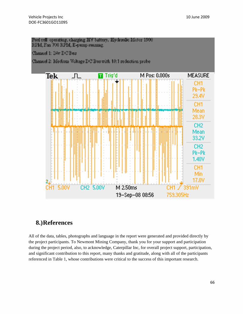
Vehicle Projects Inc 10 June 2009 DOE‐FC3601GO11095
66
8.) References All of the data, tables, photographs and language in the report were generated and provided directly by the project participants. To Newmont Mining Company, thank you for your support and participation during the project period, also, to acknowledge, Caterpillar Inc, for overall project support, participation, and significant contribution to this report, many thanks and gratitude, along with all of the participants referenced in Table 1, whose contributions were critical to the success of this important research.