licensed copy: akin koksal, bechtel ltd, 28 february 2005...
TRANSCRIPT

Lice
nsed
Cop
y: A
kin
Kok
sal,
Bec
htel
Ltd
, 28
Feb
ruar
y 20
05, U
ncon
trol
led
Cop
y, (
c) B
SI

BRITISH STANDARD BS 476-24:1987 ISO 6944-1985
Fire tests on building materials and structures —
Part 24: Method for determination of the fire resistance of ventilation ducts —
[ISO title: Fire resistance tests — Ventilation ducts]
UDC 614.841.332:620.1:69.01:697.922
Lice
nsed
Cop
y: A
kin
Kok
sal,
Bec
htel
Ltd
, 28
Feb
ruar
y 20
05, U
ncon
trol
led
Cop
y, (
c) B
SI

BS 476-24:1987
This British Standard, having been prepared under thedirection of the Fire Standards Committee, was publishedunder the authority of theBoard of BSI and comesinto effect on29 May 1987
© BSI 06-1999
The following BSI references relate to the work on this standard:Committee reference FSM/1Draft for comment 84/37753 DC
ISBN 0 580 15865 9
Committees responsible for this British Standard
The preparation of this British Standard was entrusted by the Fire Standards Committee (FSM/-) to Technical Committee FSM/1, upon which the following bodies were represented:
Association of British Roofing Felt Eurisol (UK) Association of Manufacturers Manufacturers of Mineral Insulation Fibres
Association of Building Component Fibre Building Board Organisation (FIDOR) Manufacturers Ltd. Fibre Cement Manufacturers Association
Association of Structural Fire Protection LimitedContractors and Manufacturers Fire Insurers Research and Testing
British Coal Organisation (FIRTO)British Fire Services’ Association Fire Offices CommitteeBritish Floor Covering Manufacturers’ Fire Protection Association
Association Flat Glass Manufacturers’ AssociationBritish Plastics Federation Flat Roofing Contractors’ Advisory BoardBritish Railways Board Gypsum Products Development AssociationBritish Rigid Urethane Foam Manufacturers’ Home Office
Association Institution of Fire EngineersBritish Wood Preserving Association Mastic Asphalt Council and Employers’ Cement and Concrete Association FederationChemical Industries Association National Council of Building MaterialsChief and Assistant Chief Fire Officers Producers
Association National GRP Construction FederationConcrete Society RAPRA Technology Ltd.Department of Education and Science Royal Institute of British ArchitectsDepartment of the Environment for Steel Construction Institute
Northern Ireland Timber Research and Development AssociationDepartment of the Environment (Housing and United Kingdom Antimony Oxide
Construction Industries) Manufacturers’ AssociationDepartment of the Environment (Property United Kingdom Atomic Energy Authority
Services Agency) Warrington Fire Research CentreDepartment of Transport (Marine Directorate) Wood Wool Slab Manufacturers’ AssociationElectricity Supply Industry in England and Yarsley Technical Centre Ltd.
WalesEngineering Equipment and Materials Users’
Association
The following bodies were also represented in the drafting of the standard, through subcommittees and panels:Association of Builders Hardware Guild of Architectural Ironmongers
Manufacturers Hevac AssociationBritish Steel Industry Intumescent Fire Seals AssociationDepartment of the Environment (Building National Association of Lift Makers
Research Establishment, Fire Research Suspended Ceilings AssociationStation) Thermal Insulation Manufacturers’ and
Door and Shutter Association Suppliers’ Association (TIMSA)Electric Cable Makers’ Confederation
Amendments issued since publication
Amd. No. Date of issue Comments
Lice
nsed
Cop
y: A
kin
Kok
sal,
Bec
htel
Ltd
, 28
Feb
ruar
y 20
05, U
ncon
trol
led
Cop
y, (
c) B
SI

BS 476-24:1987
© BSI 06-1999 i
Contents
PageCommittees responsible Inside front coverNational foreword ii
0 Introduction 11 Scope and field of application 12 Reference 13 Principle 14 Apparatus 25 Test conditions 26 Preparation of test specimens 37 Test arrangements 38 Procedure 49 Performance criteria for expression of fire resistance 5
10 Test report 6
Annex Explanatory notes 15
Figure 1 — Test arrangement for vertical ducts 7Figure 2 — Test arrangement for horizontal ducts 8Figure 3 — Test arrangement for measuring restraint force forhorizontal ducts at the furnace penetration point 9Figure 4 — Location of furnace thermocouples for ducts invertical position 10Figure 5 — Location of furnace thermocouples for ducts inhorizontal position 11Figure 6 — Location of thermocouples on vertical ductsoutside the furnace 12Figure 7 — Location of thermocouples on horizontal ductsoutside the furnace 13Figure 8 — Restraint of duct outside the furnace 14
Table — Fire resistance test on ventilation ducts — Necessarymeasurements 20
Publication referred to Inside back cover
Lice
nsed
Cop
y: A
kin
Kok
sal,
Bec
htel
Ltd
, 28
Feb
ruar
y 20
05, U
ncon
trol
led
Cop
y, (
c) B
SI

BS 476-24:1987
ii © BSI 06-1999
National foreword
This Part of BS 476 has been prepared under the direction of the Fire Standards Committee. It is identical with ISO 6944-1985 “Fire resistance tests — Ventilation ducts” published by the International Organization for Standardization (ISO).Terminology and conventions. The text of the international standard has been approved as suitable for publication as a British Standard without deviation. Some terminology and certain conventions are not identical with those used in British Standards; attention is drawn especially to the following.The comma has been used as a decimal marker. In British Standards it is current practice to use a full point on the baseline as the decimal marker.Wherever the words “International Standard” appear, referring to this standard, they should be read as “Part of BS 476”.Cross-references. The Technical Committee has reviewed the provisions of ISO 834-1975, to which reference is made in the text, and has decided that they are acceptable for use in conjunction with this standard. A related British Standard to ISO 834 is BS 476-20.A British Standard does not purport to include all the necessary provisions of a contract. Users of British Standards are responsible for their correct application.
Compliance with a British Standard does not of itself confer immunity from legal obligations.
Summary of pages
This document comprises a front cover, an inside front cover, pages i and ii, pages 1 to 22, an inside back cover and a back cover.This standard has been updated (see copyright date) and may have had amendments incorporated. This will be indicated in the amendment table on the inside front cover.
Lice
nsed
Cop
y: A
kin
Kok
sal,
Bec
htel
Ltd
, 28
Feb
ruar
y 20
05, U
ncon
trol
led
Cop
y, (
c) B
SI

BS 476-24:1987
© BSI 06-1999 1
0 IntroductionThis International Standard has been prepared because a fire resistance test for ventilation ducts has become necessary in order to permit evaluation of ducts designed to prevent fire spread across fire barriers in the absence of fire dampers. It should be read in conjunction with ISO 834.The Annex provides explanatory notes which give important background information, but it does not constitute a mandatory part of this International Standard.SAFETY WARNING — So that suitable precautions may be taken to safeguard health, the attention of all concerned in fire tests is drawn to the possibility that toxic or harmful gases may be evolved during the combustion of test specimens.
1 Scope and field of application1.1 This International Standard specifies a method of test and criteria for the determination of the fire resistance of vertical and horizontal ventilation ducts under standardized fire conditions.1.2 The general purpose of this test is to measure the ability of a representative duct or duct assembly to resist the spread of fire from one fire compartment to another without the aid of fire dampers.1.3 It is applicable to vertical and horizontal ducts, with or without branches, taking into account joints, air supply and exhaust openings, as well as suspension devices, etc.1.4 This International Standard is not applicable to:
a) ducts above fire-resisting suspended ceilings (horizontal membranes) in those cases where the ducts rely for their fire resistance on the performance of the ceiling;NOTE Other tests are necessary for these ducts.
b) ducts containing fire dampers at points where they pass through fire separations.
NOTE In order to assess the fire resistance of fire dampers, other tests are required. A method of test for fire dampers is under consideration as a subject for a future International Standard.
1.5 This International Standard is not appropriate for the following ducts unless the further criteria described in the Annexare established to the satisfaction of the appropriate authority:
a) ducts of materials which are extremely sensitive to thermal shock;NOTE Thermal shock may affect such ducts in a way that would differ from the effect in this test, but the test may still be used where it can be established that sensitivity to thermal shock is within acceptable limits.
b) smoke outlet ducts;NOTE These ducts need to retain their integrity andcross-sectional area under fire conditions. Consequently criteria for acceptance additional to those given in this International Standard are required. This International Standard is only applicable, therefore, to smoke outlet ducts if the criteria for integrity failure of a representative smoke outlet duct within the furnace and the loss of retention of cross-sectional area of such ducts are agreed between all parties concerned and are investigated and reported (see the Annex).
c) ducts lined on the inside with combustible material or which in practice may accumulate combustible deposits on their inside face (such as kitchen extract ducts).
NOTE Additional criteria regarding the insulation performance of the duct are required in this case (see the Annex).
1.6 This International Standard does not take into consideration the effect of impact shock loading on ducts due to the collapse of supporting or adjacent structural members or other components, or of impact- or thermal shock loading resulting from the application of a water (hose) stream.NOTE The method described in this International Standard should be used solely to measure and describe the properties of ducts and their supports in response to heat and flame under controlled laboratory conditions and should not by itself be considered or used for the description, appraisal or regulation of the fire hazard of such ducts or supports under actual fire conditions.
2 ReferenceISO 834, Fire-resistance tests — Elements of building construction.
3 Principle3.1 The test consists of measurement of the length of time for which test specimens, of specified dimensions, satisfy specified criteria under prescribed conditions during the period of exposure to fire.3.2 If a rigid restraint is not provided (see 7.2.9), measurements shall be made of any elongation or shortening of the duct which occurs during the test, in order to provide an indication of allowances for elongation or shortening which are to be made in the design of the duct system in practice.3.3 The following measurements are optional and are not to be considered an integral part of this test method.
a) gas leakage rates, to provide an indication of the potential smoke leakage through the duct;b) the release of smoke from the unexposed face, to provide an indication of smoke generated by duct covering and lining materials;
Lice
nsed
Cop
y: A
kin
Kok
sal,
Bec
htel
Ltd
, 28
Feb
ruar
y 20
05, U
ncon
trol
led
Cop
y, (
c) B
SI

BS 476-24:1987
2 © BSI 06-1999
c) restraint forces at the penetration point in the furnace wall opposing horizontal expansion of the ducts, to provide an indication of potential structural failure of lightweight partitions through which the ducts may pass; however, if the duct specimen at the penetration point isfire-stopped with mineral wool or other flexible fire-stopping, there will not be any full restraint at this point (see 7.2.9 and the Annex), and if the duct is restrained outside the furnace (see 7.2.9), it will not be appropriate to measure restraint forces at the penetration point.
3.4 The test takes into account the effect of fire exposure from the outside as well as the effect of fire entering the ducts in conditions where forced air movement may or may not be present.3.5 The test specimens incorporate the usual joints and exhaust openings and are suspended as they would be in practice. The specimens are supplied with air in a manner which is indicative of the “fan off” and “fan on” situations which could arise in practice.As the load-bearing capacity of suspension or fixing devices is often critical in a fire, additional separate evaluation of these devices is required. This evaluation may be carried out in a separate furnace. For the suspension and fixing devices, the evaluation procedure may be separated into parts, such as tests for the device for fastening to the floor, ceiling or wall, tests for the device for fastening to the duct and tests for the hangers. After having chosen the correct fastening device and hanger, the complete assembly can be evaluated.3.6 If specified by the sponsor, part of the test may be omitted if the duct concerned is not required, in practice, to meet all the conditions envisaged by the test; for example a duct designed for use only in the vertical position need not be tested in the horizontal position. Any such deviations from the full test procedure shall be clearly described in the test report.
4 ApparatusThe main items of apparatus are as follows:4.1 Furnace, capable of subjecting a ventilation duct to the standard heating and pressure conditions specified in clause 5, suitable for testing ducts in the vertical (see Figure 1) or horizontal (see Figure 2) position.4.2 Device, if applicable (see 3.3), fixed to the furnace wall, for measuring the forces which restrain thermal elongation in horizontal ducts. A test arrangement for this purpose is shown in Figure 3. Details are described in the Annex.
4.3 Thermocouples, for measuring the internal temperature of the furnace and internal and external temperatures of the test specimens in conformity with the requirements given in 5.1.2, 5.1.3 and 5.1.4 and, if necessary, a movable thermocouple (see 8.3.1.2).4.4 Equipment for measuring gas pressures in the furnace and in the ducts.4.5 Fan, for extracting gas from ducts B in Figure 1 and Figure 2 with a suction capacity of at least 2 × Vn (requiredcapacity:Vn = 3 m/s × 1 m × 0,25 m = 0,75 m3/s), i.e. sufficient to produce an air velocity in the ducts of at least 3 m/s, measured at ambient temperature before the test.The characteristic curve of the fan shall be horizontal for the actual air flow. The capacity of the fan shall not change by more than 10 % in the event of a drop in pressure of up to 50 Pa.NOTE The regulation of the gas flow can be arranged by a flow rate controller, installed just before the fan. This provides a sufficient gas flow even when deformations of the duct reducing its cross-sectional area by not more than 25 % occur. The case where the duct collapses in such a way that its cross-sectional area is reduced by more than 25 % can be disregarded in determining the fan capacity because, before this happens, a stability failure or an integrity failure at the fire-stopping would have already occurred.
For horizontal ducts, a second fan is required to produce and maintain an underpressure of 300 Pa in duct A (see Figure 2).
5 Test conditions5.1 Fire exposure
5.1.1 Temperature rise
The temperature rise shall be controlled in accordance with ISO 834, subclause 4.1.1.
5.1.2 Measurement of furnace temperature
The furnace temperature shall be measured in accordance with ISO 834, subclause 4.1.2.The positions of the thermocouples shall be as shown in Figure 4 and Figure 5.
5.1.3 Tolerances
Tolerances shall be assessed in accordance with ISO 834, subclause 4.1.3.
5.1.4 Measurement of temperature of test specimens
The temperature of the test specimens shall be measured in accordance with ISO 834,subclause 4.1.4.
Lice
nsed
Cop
y: A
kin
Kok
sal,
Bec
htel
Ltd
, 28
Feb
ruar
y 20
05, U
ncon
trol
led
Cop
y, (
c) B
SI

BS 476-24:1987
© BSI 06-1999 3
The positions of the thermocouples shall be as shown in Figure 6 and Figure 7.1) Thermocouples for estimating average temperature shall be placed in such a way as to give information representative of the normal heat transfer through the walls of the ducts.
5.1.5 Measurement of temperatures of flue gases
The gas temperatures inside the ducts shall be measured at the locations shown in Figure 6 and Figure 7. The hot junctions of the thermocouples shall be placed centrally in the ducts and at the centre of the top edge of the opening in the vertical duct A (see Figure 6). Further details are given in ISO 834, subclause 4.1.2.3.
5.2 Pressure conditions
The furnace pressure shall be maintained according to ISO 834, subclause 4.2.The neutral plane shall be below the horizontal specimen. The pressure inside horizontal duct A (see Figure 2) shall be 300 ± 10 Pa below the ambient (laboratory) pressure at the beginning of the test, and during the test the fan setting shall not be altered. The underpressure shall be continuously recorded to provide a measure of air leakage.
5.3 Air velocity
The air velocity in duct B (see Figure 1 andFigure 2) shall be 3 m/s measured at ambient temperature at the start of the test and thereafter the fan velocity shall not be readjusted. The measuring point shall be located inside the tube connecting the test specimen to the fan. The measurements shall then be corrected by the ratio of the cross-sectional areas.
6 Preparation of test specimens6.1 Dimensions
6.1.1 The test specimens shall normally be full size.6.1.2 If compliance with the requirements of 6.1.1 is not possible, the following shall be the minimum dimensions of the parts of test specimen exposed:
a) in the furnace (see Figure 1 and Figure 2 and clause A.5):
b) outside the furnace:
6.1.3 If applicable, specimens having a ratio of shortest side to longest side of 1/4 shall be tested. The longest side shall be 1 m or as near to 1 m as the dimensions of the furnace allow (see the Annex).
6.2 Conditioning
Test specimens containing hygroscopic materials, or other materials which can be affected by moisture, shall be conditioned to equilibrium with the prevailing conditions in the laboratory, which shall be within the following limits:
— temperature (dry bulb): 25 ± 15 °C;— relative humidity: 40 to 65 %.
7 Test arrangements7.1 Details of test specimens
The test shall be made on a test specimen representative of the complete duct assembly, including integral or intended insulation, on which information is required. Each type of duct requires a different approach and an attempt shall be made to reproduce the boundary conditions and the method of fixing or support inside and outside the furnace representative of that used in practice.The fire-stopping shall be as used in practice following established manuals of good practice for field installation, and shall be specified by the manufacturer. If the width of the gap forfire-stopping around the duct at the furnace penetration point is not specified, a width of 20 mm shall be used.The furnace wall which is penetrated by duct B (see Figure 2) shall, for a distance all round the duct of at least 300 mm, be constructed of lightweight concrete blocks not more than 100 mm thick or shall have a similar lightweight construction having a level of fire resistance appropriate to the duct being tested.
7.2 Duct arrangement
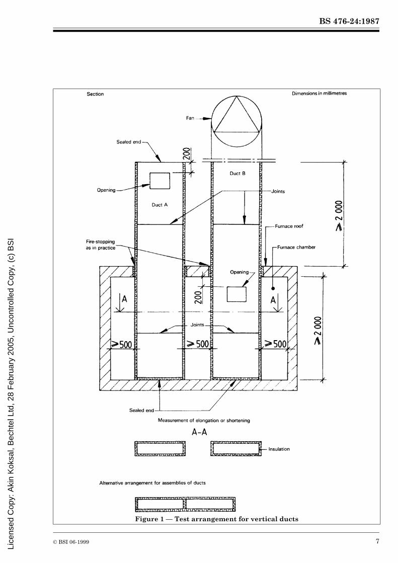
7.2.1 A single duct may be tested in the furnace, or alternatively, two or more ducts may be tested in the same furnace, provided that there is sufficient space to do so, in accordance with the dimensions shown in Figure 1 and Figure 2.
1) Additional bare wire thermocouples may be placed on supports or in other positions on the ducts to obtain additional data for use in assessments.
1) horizontal ducts: length 3,0 m,2) vertical ducts: length 2,0 m;
1) horizontal ducts: length 2,5 m,2) vertical ducts: length 2,0 m.
Lice
nsed
Cop
y: A
kin
Kok
sal,
Bec
htel
Ltd
, 28
Feb
ruar
y 20
05, U
ncon
trol
led
Cop
y, (
c) B
SI

BS 476-24:1987
4 © BSI 06-1999
7.2.2 Ducts shall be arranged as in practice (see Figure 1 and Figure 2). Both horizontal ducts shall abut against the furnace wall at one end and shall penetrate the furnace wall at the other. Both the end of the horizontal duct A (see Figure 2) within the furnace and the end of the branch duct attached thereto shall be closed independently of any furnace enclosure by materials and construction similar to the remainder of the duct.7.2.3 Vertical ducts (see Figure 1) shall be tested standing on the furnace floor and penetrating the furnace roof slab; the ducts shall be fixed at the furnace roof level as they would be fixed in practice when penetrating a floor.7.2.4 For horizontal ducts, the test arrangement shall include at least two joints inside the furnace and at least one joint outside it. One joint shall be at the centre of the span between the supports both inside and outside the furnace, if this is possible in practice.7.2.5 For vertical ducts, the test arrangement shall include at least one joint inside and one joint outside the furnace (see Figure 1).7.2.6 The openings of all ducts shall have an area which is at least half the cross-sectional area of the ducts. Such openings shall be in the positions shown in Figure 1 and Figure 2.7.2.7 The horizontal duct A (see Figure 2) shall include one sharp bend of the same cross-sectional area as the main duct and a T-piece to form a short branch duct. All specimens including this branch shall be mounted with the suspension or fixing devices as would be provided in practice.7.2.8 There shall be a clearance of 500 ± 50 mm between the top of the horizontal duct and the ceiling, and also at least 500 mm between the underside of the horizontal duct and the floor. Similarly, there shall be a clearance of at least 500 mm between the sides of ducts and the furnace walls, except in the case of assemblies of ducts as shown in Figure 1 and Figure 2.7.2.9 When, in practice, horizontal ducts and/or the applied fire protective insulation outside the fire compartment is likely to be subject to rigid restraint against elongation forces, either from building works (walls, etc.) against which the duct abuts, or where the rest of the duct assembly outside the fire compartment could afford such rigid restraint (such as may be afforded by ducts with short, rigid supports), full restraint shall be produced in the specimen at points 2 000 ± 50 mm from and outside the furnace enclosure.
Such restraint shall be full in the direction of the duct, so as to resist all expansion forces in this direction, but there shall be no restraint (at ambient temperature) to movement in the vertical direction.In these cases, the measurement of restraint forces and elongations are not applicable. In other cases, the parts of specimens outside the furnace shall be unrestrained.
7.3 Materials and workmanship
The materials and standard of workmanship of the test specimens shall be representative of good practice, as defined by national codes and standards.
8 Procedure8.1 Test conditions
Parts of ducts within the furnace shall normally be exposed to fire from all sides over their whole length. Ducts shall only be exposed on less than four sides if this is likely to occur in practice. Tests can be performed on assemblies of ducts (see Figure 1). Alternatively, tests can be performed with a duct positioned close to a wall or floor if it is desired to represent this condition in practice.
8.2 Control of conditions to permit assessment of integrity
Twenty minutes after the start of the test, stop the fan in duct B (see Figure 1 and Figure 2) and, where it is intended to evaluate the “fire outside duct” situation with the duct only in the horizontal position (see 3.6), stop the fan in horizontal duct A (see Figure 2) for about 5 min to enable an assessment of integrity of the duct assembly outside the furnace to be carried out under stable conditions in the “fan off” situation. Then start the fan in duct B and, where applicable, in horizontal duct A, and stop it for a 5 min period 10 min before the completion of every 30 min period of the test. Make assessments of integrity in the “fan on” situation at all other times.
8.3 Test measurements and observations
8.3.1 Assessment of fire resistance
Make the following measurements and observations to enable the criteria of stability, insulation and integrity (see clause 1) to be assessed.
8.3.1.1 Stability
Record the time when the suspension or fixing devices can no longer retain a duct in its intended position or when sections of the duct collapse.
Lice
nsed
Cop
y: A
kin
Kok
sal,
Bec
htel
Ltd
, 28
Feb
ruar
y 20
05, U
ncon
trol
led
Cop
y, (
c) B
SI

BS 476-24:1987
© BSI 06-1999 5
8.3.1.2 Insulation (temperature of unexposed face)
Measure the average and maximum temperatures of the unexposed faces of the test specimens as specified in 5.1.4 and ISO 834, subclause 6.2.2.1, using a movable thermocouple to locate points of high temperature.
8.3.1.3 Integrity
a) Record any cracks and openings which indicate loss of integrity.b) Determine the time at which the passage of flames or of hot gases outside the furnace occurs according to ISO 834, subclause 6.2.3.1, the cotton pad being applied to the openings outside the duct, if provided, and to any crack or hole which develops.c) Measure and record the temperature of the gases issuing from openings in the ducts outside the furnace and at penetration points inside the ducts. (See Figure 6 and Figure 7; thermocouples 1 and 2 are used.)
8.3.2 Restraint forces and thermal elongation or shortening
If applicable, measure and record the restraint force in duct B (see Figure 2) at the penetration point [see 3.3 c)].Measure and record the thermal elongation or shortening of ducts A (see Figure 1 and Figure 2) at the penetration point, where no rigid restraint is provided in accordance with 7.2.9.
8.3.3 Additional observations
Throughout the test, make observations of all changes and occurrences which do not affect the performance criteria but which could create hazards in a building, including, for example:
a) deflections;b) the emissions of smoke or noxious fumes from the unexposed face of a duct, for example attributable to its coverings and/or lining;c) a decrease in cross-sectional area of the ducts (in order to provide information on the ability of the ducts to serve as smoke extraction ducts).
8.4 Duration of the test
8.4.1 Normally, the test specimen shall be heated in the prescribed manner until failure occurs under any one of the relevant performance criteria, namely
a) stability (see 9.2.1);b) insulation (see 9.2.2);c) integrity (see 9.2.3).
8.4.2 In tests other than those on test specimens judged only by the criterion of stability (see 9.2.1), testing may be continued after failure under either of the other two criteria (see 9.2.2 and 9.2.3) by prior agreement between the sponsor of the test and the testing authority, until failure occurs under the other criterion, provided that collapse of the specimen has not already occurred.8.4.3 Alternatively, the test may be concluded after a period determined by prior agreement between the sponsor and the testing authority, even if no failure under any of the criteria has occurred at the end of that period.8.4.4 The length of time from the commencement of heating for which the test specimen complies with the relevant requirement(s) shall be expressed in minutes.
8.5 Calibration
The instrumentation used for measuring temperature, pressure, air velocity and force shall be calibrated, using established reference standards, and instrument readings shall be corrected as appropriate. Any measurement uncertainty shall be reported.
9 Performance criteria for expression of fire resistance9.1 General
The fire resistance of test specimens shall be the duration, in minutes, of heating in accordance with 5.1.1 until failure occurs according to one or more of the performance criteria, i.e. stability, insulation, integrity, or until the test is terminated, whichever is the shortest time.In expressing the test result, the words “stability”, “insulation” and “integrity” shall be followed by the time expressed in minutes, denoting the period of successful compliance under each of these headings.
9.2 Performance criteria
9.2.1 Stability
Stability failure shall be deemed to have occurred in duct A within the furnace and in ducts A and B outside the furnace when the duct collapses in such a manner that the duct no longer fulfils its intended function.
9.2.2 Insulation
Insulation failure shall be deemed to have occurred when the temperature rise above initial ambient temperature in the laboratory on the unexposed surface of the test specimen outside the furnace exceeds either
a) 140 °C as an average value (see 5.1.4); or
Lice
nsed
Cop
y: A
kin
Kok
sal,
Bec
htel
Ltd
, 28
Feb
ruar
y 20
05, U
ncon
trol
led
Cop
y, (
c) B
SI

BS 476-24:1987
6 © BSI 06-1999
b) 180 °C as a maximum value read by any surface thermocouple.
NOTE See also the Annex, clause A.1 d) in respect of insulation failure of ducts A in Figure 1 and Figure 2 within the furnace where such ducts contain combustible materials, clause A.7.1, regarding the need for care in siting openings into ducts close to fire separation walls.
9.2.3 Integrity
The presence and formation in the test specimen of cracks, holes or other openings outside the furnace through which flames or hot gases can pass shall constitute integrity failure.Integrity failure shall also be deemed to have occurred when the cotton pad referred to in ISO 834, subclause 6.2.3.1, is ignited or when sustained flaming, of duration at least 10 s, appears on the unexposed face of the test specimen outside the furnace.
9.3 Precision and accuracy
No quantitative data for precision and accuracy are available at present.
10 Test reportThe test report shall include the following information:
a) name of testing laboratory;b) name of sponsor;c) date of test;d) name of manufacturer and the trade name (if any) of the product;
e) details of construction and conditioning of the test specimens, including detailed information on the relevant physical and mechanical properties of the materials used, together with drawings illustrating the essential features and including the number of sides of the test specimens exposed to fire in the furnace (see 8.1);f) whether the duct was considered restrained or unrestrained, including methods of fixing, support and mounting, as appropriate for the type of specimen, and a description of the method and materials used to seal the opening between the duct and cut-out provided in the wall to accommodate the duct;g) the force (if measured) due to restraint at the furnace penetration point as a function of time, presented as a graph;h) the thermal elongation or shortening (if measured) of ducts A in Figure 1 and Figure 2 (see 8.3.2);j) other observations made during the test according to 8.3, including a complete record of measured temperatures as a function of time;k) test results as required by clause 9. Where the test is terminated before the occurrence of failure under the relevant criteria, this shall be reported.
Lice
nsed
Cop
y: A
kin
Kok
sal,
Bec
htel
Ltd
, 28
Feb
ruar
y 20
05, U
ncon
trol
led
Cop
y, (
c) B
SI
BS 476-24:1987
© BSI 06-1999 7
Figure 1 — Test arrangement for vertical ducts
Lice
nsed
Cop
y: A
kin
Kok
sal,
Bec
htel
Ltd
, 28
Feb
ruar
y 20
05, U
ncon
trol
led
Cop
y, (
c) B
SI

BS 476-24:1987
8 © BSI 06-1999
Figure 2 — Test arrangement for horizontal ducts
Lice
nsed
Cop
y: A
kin
Kok
sal,
Bec
htel
Ltd
, 28
Feb
ruar
y 20
05, U
ncon
trol
led
Cop
y, (
c) B
SI

BS
476-24:1987
© B
SI 06-1999
9
Figure 3 — Test arrangement for measuring restraint force for horizontal ducts at the furnace penetration point
Lice
nsed
Cop
y: A
kin
Kok
sal,
Bec
htel
Ltd
, 28
Feb
ruar
y 20
05, U
ncon
trol
led
Cop
y, (
c) B
SI

BS 476-24:1987
10 © BSI 06-1999
Figure 4 — Location of furnace thermocouples for ducts in vertical position (see also Figure 1)
Lice
nsed
Cop
y: A
kin
Kok
sal,
Bec
htel
Ltd
, 28
Feb
ruar
y 20
05, U
ncon
trol
led
Cop
y, (
c) B
SI

BS 476-24:1987
© BSI 06-1999 11
Figure 5 — Location of furnace thermocouples for ducts in horizontal position (see also Figure 2)
Lice
nsed
Cop
y: A
kin
Kok
sal,
Bec
htel
Ltd
, 28
Feb
ruar
y 20
05, U
ncon
trol
led
Cop
y, (
c) B
SI

BS 476-24:1987
12 © BSI 06-1999
Figure 6 — Location of thermocouples on vertical ducts outside the furnace (see also Figure 1)
Lice
nsed
Cop
y: A
kin
Kok
sal,
Bec
htel
Ltd
, 28
Feb
ruar
y 20
05, U
ncon
trol
led
Cop
y, (
c) B
SI

BS 476-24:1987
© BSI 06-1999 13
Figure 7 — Location of thermocouples on horizontal ducts outside the furnace
Lice
nsed
Cop
y: A
kin
Kok
sal,
Bec
htel
Ltd
, 28
Feb
ruar
y 20
05, U
ncon
trol
led
Cop
y, (
c) B
SI

BS 476-24:1987
14 © BSI 06-1999
Figure 8 — Restraint of duct outside the furnace
Lice
nsed
Cop
y: A
kin
Kok
sal,
Bec
htel
Ltd
, 28
Feb
ruar
y 20
05, U
ncon
trol
led
Cop
y, (
c) B
SI

BS 476-24:1987
© BSI 06-1999 15
Annex Explanatory notes
(This Annex does not form part of the standard.)A.0 GeneralThe following explanatory notes are intended to serve as guidance for the planning, performance and reporting of a fire resistance test carried out in conformity with this International Standard.A fundamental requirement for fire resistance tests is that the test results shall be reproducible. This requirement necessitates very accurate detailed specification of the test conditions, for the preparation of the test specimens and the characteristics of heating and restraint during the test.Detailed data from a fire resistance test will also facilitate classification and the international utilization of the test data in countries with different classification requirements. For a satisfactory analysis of the test results, it may be necessary to complement a fire resistance test by other tests for the determination of the relevant properties of materials, for example thermal conductivity, specific heat, and strength and deformation properties in the temperature range associated with fires.Since the duct, in practice, will be attached to fixed building members (floors, walls, etc.), the anticipated effects of their expansion, contraction or deflection should be considered in a complete evaluation of fire performance.It may also be necessary to carry out additional tests of the load-bearing capacity and resistance to elongation or other deformation of hangers under fire conditions.A.1 Notes on scope and field of applicationVentilation duct systems are well known for creating hazards by facilitating the spread of smoke and hot gases in the case of fire. Systems of this type are often complicated and extensive in modern buildings and their influence on the fire hazard has to be considered carefully. The fire hazard can be reduced either by providing fire dampers (tests on which are not covered by this International Standard) at the points where the ducts pass through fire separations, or by the provision of ducts which, themselves, are fire-resisting.
It is obvious that the impact of fire on a ventilation duct system, as well as the spread of fire through the system, can vary within a very wide range. A strict scientific approach to the problem of adequate testing of a ventilation duct would, therefore, be to design a series of tests each of which corresponds to a specified fire situation and duct arrangement. However, such an approach would probably fail due to its economic consequences, as tests of this type are very time-consuming and costly. The method of test described in this International Standard has therefore been designed with the intention of covering a wide range of fire situations in one single test corresponding to a “worst case” situation.The worst case cannot be specified uniquely in every possible situation and it has, therefore, been necessary to accept some restrictions and lack of applicability of the method of test to all situations. The most important exclusion from the scope of this International Standard is an uninsulated ventilation duct located in the space immediately below the floor structure and protected against fire by a suspended ceiling of sufficient fire resistance, where other tests for the fire performance of the suspended ceiling may be used.The method described in this International Standard is also not appropriate in the following contexts, unless the further criteria described are established to the satisfaction of the appropriate authority:
a) A ventilation duct constructed of materials which are extremely sensitive to thermal shock, for the case when cold air passes through a fire compartment; the duct is thus attacked by fire from the outside whilst being cold on the inside. Here the thermal shock or other phenomena may cause the behaviour of the duct to be worse in practice than in the fire test, but if the sensitivity to shock is within agreed acceptable limits, the method of test described may still be used.
Lice
nsed
Cop
y: A
kin
Kok
sal,
Bec
htel
Ltd
, 28
Feb
ruar
y 20
05, U
ncon
trol
led
Cop
y, (
c) B
SI
BS 476-24:1987
16 © BSI 06-1999
b) Ventilation duct systems intended solely for the evacuation of smoke, which are intended to maintain their integrity and cross-sectional area within the fire compartment in order to enable the maximum quantity of smoke to be extracted throughout the fire period. In this case, any excessive leakage through the walls of the duct within the fire compartment (as well as outside it), and any restriction of the cross-sectional area of the duct due to twisting or buckling may impair the ability of the duct to extract the amount of smoke for which it was designed. It is considered that any restriction of the cross-sectional area of the duct to 75 % or less of its original area should be deemed to constitute failure in this case. It should be noted that, in practice, such ducts may cause movement of the smoke at higher velocities than in normal ventilation ducts (disregarding the noise). The high under-pressure in such situations may cause collapse of the duct. c) Ducts lined on the inside with combustible materials or ducts, such as kitchen extract ducts, which are likely to accumulate combustible deposits. These may be tested in accordance with this International Standard if additional thermocouples are fixed at points on the inner surface of the duct within the furnace where hot spots are anticipated. Combustible linings (either external or internal) may be subject to certain requirements regarding spread of flame, fire propagation, etc. It has been found most convenient to exclude these properties from the test and to test them separately.d) Special problems may occur when adjacent structural members (for example floors), from which horizontal ventilation ducts are suspended, deflect due to the thermal influence of the fire. The test results may then be difficult to interpret. The problem is of the same nature as mentioned in ISO 834 for non-load-bearing partitions and reference should, therefore, be made to the Annex to ISO 834, A.6.1, note concerning 6.1.1.5.Due to composite reactions caused by deflections of the ventilation duct and of the adjacent structural member, suspension and fastening devices, bolts, etc. may fail. However, it is emphasized that the method of test specified in this International Standard is not primarily intended to test such devices but the ventilation duct itself. Devices of this type should normally be evaluated separately. This means that failure of one or more fastening devices which are not specific to the particular duct assembly should not automatically be interpreted as a failure of the whole duct assembly.
e) In the case of a fire inside a horizontal duct (duct B in Figure 2), duct hangers outside the furnace are liable to be attacked by the fire, for example where they cannot be well insulated on the side nearest to the duct. In this case a separate test, in addition to those mentioned in d) above, may be necessary on representative hangers, together with a section of the duct loaded as in practice.
A.2 Notes on principleA.2.1 Smoke productionIn 8.3.3, additional observations during the test, for example the emission of smoke or noxious fumes from the unexposed face of a duct, are required to be reported. This has been specified in order to facilitate the assessment of the overall fire hazard in a building.As the combustion by the burners of the furnace does not produce visible smoke, and as it may be difficult to distinguish between smoke and any steam produced, the test gives no full and reliable indication of the quantity of smoke which could be passed by the duct from the burning room to other rooms of a building. The estimation of this has to be based on observations in accordance with 8.3.1.3.In the case of ducts constructed of, or lined with, combustible materials, smoke can be produced by thermal decomposition of the duct or lining material and can enter other rooms. The estimation as to whether this represents a hazard depends on the amount and density of the smoke. A quantitative method of measuring this does not exist at present, but the following simple aid to assessment has proved to be suitable. This shall not, however, be allowed to interfere with measurements and observations required by this International Standard, such as observations of integrity failure.A second room with the duct passing through it is constructed alongside or, as the case may be, on top of the furnace. The walls and the ceiling of this room can be constructed of simple light elements as the room is not heated by the burners. The room should be completely enclosed in order to collect the smoke which is emitted by the duct. From visual observation, the time can be established at which the density of smoke in the room is estimated to be such that it represents a danger for escaping persons. In order to have a common basis for this estimation the suggested dimensions of the room are 3,5 m × 3,5 m × 2 m. It can be assumed that an acceptable smoke level in a room of this size will be at least as acceptable in a larger room.
Lice
nsed
Cop
y: A
kin
Kok
sal,
Bec
htel
Ltd
, 28
Feb
ruar
y 20
05, U
ncon
trol
led
Cop
y, (
c) B
SI

BS 476-24:1987
© BSI 06-1999 17
In relation to integrity it is recognized that the rise in temperature of thermocouple 1 at the furnace penetration points will only give a rough indication of integrity failure of ducts A, within the furnace, although it will give some indication of insulation failure within the furnace. The introduction of a tracer gas into the furnace and measurement of it within the duct may be a more precise method of measuring integrity failure. Also, the measurement and comparison of the amount of carbon dioxide within the furnace and within the duct may enable a rate of gas leakage to be ascertained.Another method for estimating the leakage under fire conditions as an indication of integrity failure is the measurement of under-pressure in duct A; see 5.3.A.3 Notes on apparatusA.3.1 ReproducibilityAt present, no information is available concerning the reproducibility of this method of test. In order to establish the reproducibility, calibration tests or round-robin tests will have to be performed.A.3.2 Thermal elongation and shortening and restraint forcesDuring fire exposure, the ducts can expand or shrink due to high temperatures. This may cause premature failure of a non-load-bearing lightweight partition if the duct is fixed to it or butts against it. The expansion or shrinkage of the duct will apply a force to the partition.Therefore, during tests, joints, attachment devices and a representative partition with fire-stopping are considered as being parts of the duct system being evaluated. Alternative joints, attachment devices, fire-stoppings, etc., should not be used unless it can be shown that the performance in respect to integrity and stability will not be worse and that the force on the partition resulting from expansion or shrinkage will not be greater.As a consequence of the limitation of the force on a partition resulting from expansion, slidingfire-stopping devices are often chosen at the point of penetration through walls or partitions. Consequently, in this system, the installation of the duct must provide enough space and sufficiently flexible duct supports to allow for thermal elongation or shortening under fire conditions. The space required, based on the results of measurements of the elongation or shortening, shall be given in the test report.
In the case of horizontal ducts where the installation cannot ensure the required space for the elongation of the ducts or sufficient flexibility in the duct supports, a test with full restraint inside and outside the duct has to be performed if the laboratory cannot judge by experience that the restraint has no negative influence on the results. Duct B, in this case, should be fully restrained in the direction of the duct at the end inside the furnace and at a point 2 m outside the furnace, but there should be no restraint in a vertical direction. This will represent the “worst case” condition where, for example, a duct butts against a corridor a short distance away from the fire compartment, or where the “cold” portions of the duct system outside the fire compartment act as a rigid restraint to the expansion forces. A suitable method of restraining the duct specimen outside the furnace is shown in Figure 8.If applicable, details of the arrangement for measuring the restraint force at the penetration point are given in Figure 3.A.4 Notes on test conditionsA.4.1 Temperature-time developmentIf the ventilation ducts are assumed to be subjected to a fully developed fire, the temperature-time curve according to ISO 834 is chosen. Other fire curves could be discussed, but their scientific background has been found insufficient to permit an alternative proposal.A.4.2 Anticipated pressure rangesThe movement of air in a duct passing through a compartment on fire, and which has no openings to that compartment, may create an underpressure on the duct walls which may encourage the fire to exploit any cracks which develop in the duct. An underpressure of 300 ± 10 Pa in horizontal duct A has been chosen as being realistic in this “worst case” situation and is the underpressure at which any integrity failure of the specimen within the furnace shall be measured.A.4.3 Measurements of temperature of test specimensThe temperature measurements are assumed to be carried out as specified in the relevant clauses of ISO 834, with additional measurements being necessary because of the special nature of the test specimens. In particular, an additional temperature measurement is specified for the separating wall between two ducts built together, one of which is carrying fire gases. It has tentatively been proposed that 300 °C should be the maximum acceptable temperature on the unexposed side of such a separating wall.
Lice
nsed
Cop
y: A
kin
Kok
sal,
Bec
htel
Ltd
, 28
Feb
ruar
y 20
05, U
ncon
trol
led
Cop
y, (
c) B
SI

BS 476-24:1987
18 © BSI 06-1999
A.5 Notes on preparation of test specimensThe test specimen shall be representative of duct installations in practice. This implies that joints, suspension and fixing devices, bolts, etc., shall be included and mounted in accordance with the manufacturer’s mounting instructions. The distance separating joints and the span between supports should be sufficient to enable interpolation within a range of other lesser dimensions to be made. In some situations, the furnace may be too small to reproduce a relevant fire exposure in a particular duct assembly. This implies that the duct assembly to be used in practice may need to be modified in order to fit it into the furnace.In most cases, the largest ducts likely to be used and which can be accommodated in the furnace whilst maintaining the specified velocity in the duct (i.e. 3 m/s) shall be tested. Unjustifiable extrapolation to ducts restrained in a different manner, supported at greater intervals or of a larger size, should not be made. Care should be taken when making any assessment of the performance of ducts which do not entirely conform in practice with the conditions represented in the test.Distortion of rectangular ducts is generally more severe than distortion of square or round ducts. Hence, the maximum width to height ratio intended for use shall be tested. In other cases, or if the ratio is not specified, the test specimens should have walls with a ratio of 1/4, the longest side being 1 m if possible. The longest side of the horizontal specimen should normally be orientated horizontally in the furnace.This International Standard requires the testing of a minimum length of 3,0 m for horizontal ducts and 2,0 m for vertical ducts inside the furnace and 2,5 m and 2,0 m, respectively, outside the furnace. These lengths have been chosen in order to use the fire test furnaces available in most countries. Some laboratories have larger furnaces and can consequently test larger or longer test specimens: this is most desirable. In some cases, they can obtain more comprehensive results from the tests.A.6 Notes on test arrangementsFor the safety of personnel, all heated gases exhausted from the ducts being tested should be directed outside the test laboratory.
A.7 Notes on procedureA.7.1 Insulation and integrityThe procedure includes periods during which the fans are running, interrupted by periods when the fans are stopped. This regime is used to enable a check of the insulation and integrity properties to be made in various typical circumstances, but it is not representative of conditions in practice as far as one duct is concerned.Assuming cut-out of the ventilating fan in the event of a fire, the temperature of the gases within an insulated duct, exposed on the exterior to fire conditions, will rise both due to heat transfer through the duct wall and due to any failure in integrity.A measure of the likely temperature of gases diffusing through the system away from the fire compartment may be obtained from thermocouple 2, reading the gas temperature within duct A inFigure 6 and Figure 7. The temperature of gases at this point is not considered as a failure criterion, because the significance of the temperature and what the maximum permissible temperature should be at this point would depend on the proximity of combustible material and the presence of air grilles. This temperature should, however, be recorded because there is, in practice, the risk of fire gases penetrating into an adjacent compartment, depending on the pressure difference. If an opening into the system is sited close to a fire separating wall, then appropriate protection against the diffusion of hot gases into the compartment should be provided.Some countries may wish to specify the size of cracks, holes or other openings outside the furnace which shall constitute integrity failure.In the event of a fan continuing to operate, the overpressure from a supply fan will normally exceed the buoyancy pressure of the fire, preventing fire gases entering the system; any negative pressure differential maintained by an extraction fan will only serve to assist the evacuation of hot gases to the atmosphere.A.7.2 StabilityThe criterion for stability failure is only relevant inside the furnace for ducts A, and not for ducts B. Outside the furnace, however, both ducts A and B are subject to the criterion for stability failure. Any collapse or failure of fixing devices, etc., in respect of ducts B within the furnace should, nevertheless, be reported under 8.3.3.
Lice
nsed
Cop
y: A
kin
Kok
sal,
Bec
htel
Ltd
, 28
Feb
ruar
y 20
05, U
ncon
trol
led
Cop
y, (
c) B
SI
BS 476-24:1987
© BSI 06-1999 19
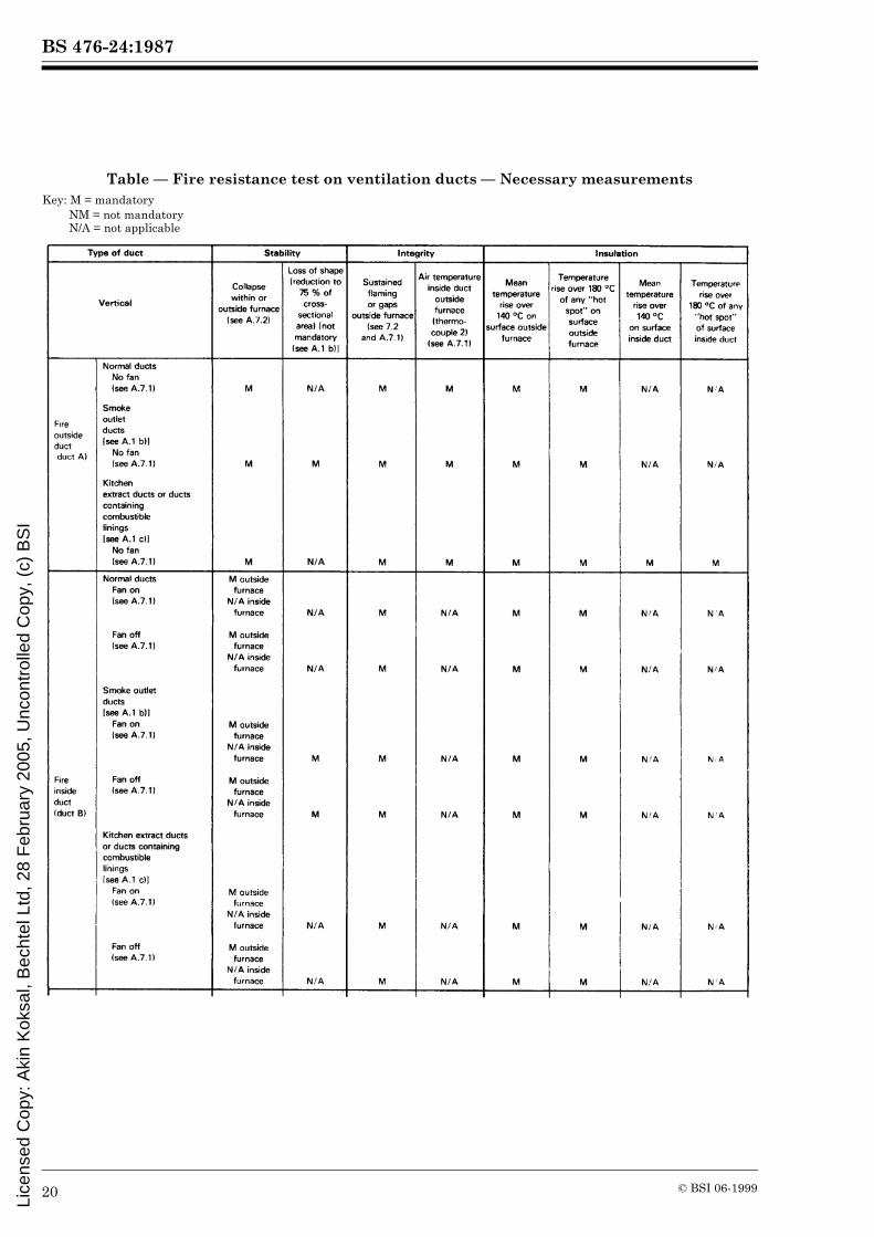
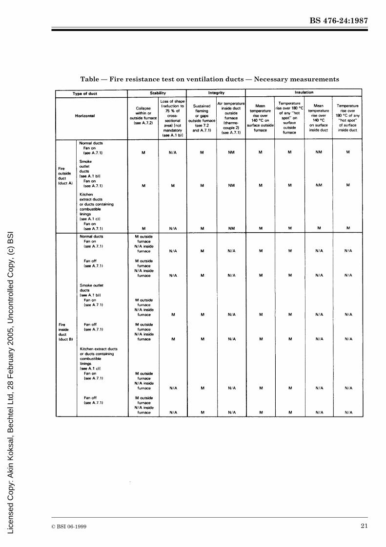
A.8 Notes on failure criteriaThe importance of the various failure criteria of stability, integrity and insulation may vary according to whether the duct is a normal ventilation duct, a “smoke outlet” duct or a “kitchen extract” duct as described above. For convenience of reference to appropriate items in this International Standard, the failure criteria are analysed in the following summary table, with an indication given as to the status of each particular case. The footnotes to the table indicate other tests and measurements which may be required.
Lice
nsed
Cop
y: A
kin
Kok
sal,
Bec
htel
Ltd
, 28
Feb
ruar
y 20
05, U
ncon
trol
led
Cop
y, (
c) B
SI
BS 476-24:1987
20 © BSI 06-1999
Table — Fire resistance test on ventilation ducts — Necessary measurementsKey: M = mandatory
NM = not mandatoryN/A = not applicable
Lice
nsed
Cop
y: A
kin
Kok
sal,
Bec
htel
Ltd
, 28
Feb
ruar
y 20
05, U
ncon
trol
led
Cop
y, (
c) B
SI
BS 476-24:1987
© BSI 06-1999 21
Table — Fire resistance test on ventilation ducts — Necessary measurements
Lice
nsed
Cop
y: A
kin
Kok
sal,
Bec
htel
Ltd
, 28
Feb
ruar
y 20
05, U
ncon
trol
led
Cop
y, (
c) B
SI

BS 476-24:1987
22 © BSI 06-1999
NOTE 1 Additional tests may be carried out to evaluate suspension and fastening devices [see A.1 d) and e)].NOTE 2 Measurements (non-mandatory) may also be made and criteria established by the relevant authorities in respect of
a) the temperature of the unexposed surface of the dividing wall between an assembly of vertical ducts, 300 °C being the suggested failure criterion (see A.4 and Figure 6);b) sensitivity to thermal shock [see 1.5 a)];c) gas leakage rates [see 3.3 a)];d) smoke production [see 3.3 b) and A.2.1];e) elongation or shortening of the specimen (see 8.3.2 and A.3.2);f) restraint forces (see 8.3.2 and A.3.2).
Lice
nsed
Cop
y: A
kin
Kok
sal,
Bec
htel
Ltd
, 28
Feb
ruar
y 20
05, U
ncon
trol
led
Cop
y, (
c) B
SI
BS 476-24:1987
© BSI 06-1999
Publication referred to
See national foreword.
Lice
nsed
Cop
y: A
kin
Kok
sal,
Bec
htel
Ltd
, 28
Feb
ruar
y 20
05, U
ncon
trol
led
Cop
y, (
c) B
SI

BS 476-24:1987ISO 6944-1985
BSI389 Chiswick High RoadLondonW4 4AL
BSI — British Standards InstitutionBSI is the independent national body responsible for preparing British Standards. It presents the UK view on standards in Europe and at the international level. It is incorporated by Royal Charter.
Revisions
British Standards are updated by amendment or revision. Users of British Standards should make sure that they possess the latest amendments or editions.
It is the constant aim of BSI to improve the quality of our products and services. We would be grateful if anyone finding an inaccuracy or ambiguity while using this British Standard would inform the Secretary of the technical committee responsible, the identity of which can be found on the inside front cover. Tel: 020 8996 9000. Fax: 020 8996 7400.
BSI offers members an individual updating service called PLUS which ensures that subscribers automatically receive the latest editions of standards.
Buying standards
Orders for all BSI, international and foreign standards publications should be addressed to Customer Services. Tel: 020 8996 9001. Fax: 020 8996 7001.
In response to orders for international standards, it is BSI policy to supply the BSI implementation of those that have been published as British Standards, unless otherwise requested.
Information on standards
BSI provides a wide range of information on national, European and international standards through its Library and its Technical Help to Exporters Service. Various BSI electronic information services are also available which give details on all its products and services. Contact the Information Centre. Tel: 020 8996 7111. Fax: 020 8996 7048.
Subscribing members of BSI are kept up to date with standards developments and receive substantial discounts on the purchase price of standards. For details of these and other benefits contact Membership Administration. Tel: 020 8996 7002. Fax: 020 8996 7001.
Copyright
Copyright subsists in all BSI publications. BSI also holds the copyright, in the UK, of the publications of the international standardization bodies. Except as permitted under the Copyright, Designs and Patents Act 1988 no extract may be reproduced, stored in a retrieval system or transmitted in any form or by any means – electronic, photocopying, recording or otherwise – without prior written permission from BSI.
This does not preclude the free use, in the course of implementing the standard, of necessary details such as symbols, and size, type or grade designations. If these details are to be used for any other purpose than implementation then the prior written permission of BSI must be obtained.
If permission is granted, the terms may include royalty payments or a licensing agreement. Details and advice can be obtained from the Copyright Manager. Tel: 020 8996 7070.
Lice
nsed
Cop
y: A
kin
Kok
sal,
Bec
htel
Ltd
, 28
Feb
ruar
y 20
05, U
ncon
trol
led
Cop
y, (
c) B
SI