lid-driven cavity flow of viscoelastic liquids · the lid-driven cavity flow is a well-known...
TRANSCRIPT

1
Lid-driven cavity flow of viscoelastic liquids
R G Sousa 1, R J Poole2, A M Afonso1, F T Pinho3, P J Oliveira4, A Morozov5 and M A Alves1*
1Dep. of Chemical Eng., CEFT, Faculty of Engineering, University of Porto, 4200-465 Porto, Portugal
2School of Eng., University of Liverpool, Liverpool L69 3GH, UK
3 Dep. of Mechanical Eng., CEFT, Faculty of Engineering, University of Porto, 4200-465 Porto, Portugal
4 Dep. Eng. Electromecanica, C-MAST Unit, Universidade da Beira Interior, 6201-001 Covilhã, Portugal
5 School of Physics and Astronomy, University of Edinburgh, Edinburgh EH9 3JZ, UK
*Corresponding author: [email protected]
Abstract
The lid-driven cavity flow is a well-known benchmark problem for the validation of new
numerical methods and techniques. In experimental and numerical studies with viscoelastic
fluids in such lid-driven flows, purely-elastic instabilities have been shown to appear even at
very low Reynolds numbers. A finite-volume viscoelastic code, using the log-conformation
formulation, is used in this work to probe the effect of viscoelasticity on the appearance of such
instabilities in two-dimensional lid-driven cavities for a wide range of aspect ratios (0.125 ≤
Λ=height/length ≤ 4.0), at different Deborah numbers under creeping-flow conditions and to
understand the effects of regularization of the lid velocity. The effect of the viscoelasticity on the
steady-state results and on the critical conditions for the onset of the elastic instabilities are
described and compared to experimental results.
KEYWORDS: UCM model, Oldroyd-B model, purely-elastic flow instability, velocity
regularization, finite-volume method, log-conformation tensor.

2
1 Introduction
The fluid motion in a box induced by the translation of one wall – the so-called “lid-driven
cavity flow” – is a classic problem in fluid mechanics [1]. The geometry is shown schematically
in Figure 1 and conventionally comprises a two-dimensional rectangular box of height H and
width L of which the top (horizontal) wall – the “lid” – translates horizontally at a velocity U (for
single phase fluids flowing isothermally the exact choice of moving wall is unimportant). For
Newtonian fluids in rectangular boxes, the problem is governed by two dimensionless
parameters: the Reynolds number Re (≡ ρUH/η) and the aspect ratio Λ (≡ H/L), where ρ is the
fluid density and η is the dynamic viscosity. For very low Reynolds numbers – creeping-flow
conditions, where Re → 0 – and low aspect ratios (Λ<1.6 [2]) a main recirculating region of fluid
motion is induced which, due to the linearity of the Navier-Stokes equations under Stokes flow
conditions, is symmetric about the vertical line x/L=0.5, as shown in Figure 1. In addition to this
main recirculation, smaller Moffatt [3] or corner eddies are also induced at the bottom corners
(labelled “C” and “D” in Figure 1): in fact at the bottom corners there is an infinite series of
these vortices of diminishing size and strength as the corner is approached [3]. The primary
corner eddies grow in size with increasing aspect ratio and, at a critical aspect ratio of about
1.629 [2], merge to form a secondary main cell albeit of much smaller intensity than the primary
main cell (Ref. [1] gives a stream function decay ratio of 1/357 for these main cells). For higher
aspect ratios this process repeats and additional main cells are created. Thus for “high” aspect
ratios, essentially Λ>1.6, the main fluid motion near the translating wall (the main cell) is
essentially unaffected by the aspect ratio. For a fixed aspect ratio – the majority of studies use
Λ=1 – increasing the Reynolds number firstly breaks the fore-aft symmetry about the vertical
line x/L=0.5 and then simulations reveal increasing complexity [1, 4]. Since experiments show
[5] that above a critical Reynolds number of around 500 the flow becomes three-dimensional and
then time-dependent (Re ≈ 825), we will not discuss these high Re steady two-dimensional
simulations further here. Given the geometrical simplicity, combined with the rich observable
fluid dynamics, the lid-driven cavity became a benchmark problem in the (Newtonian) fluid
mechanics community for the development and validation of numerical schemes and
discretization techniques [1,4,6,7].

3
For viscoelastic fluids the literature is understandably less dense but, at least under creeping-flow
conditions, much has been revealed by the limited number of studies to date. Fluid
viscoelasticity introduces two additional non-dimensional parameters to the problem: the
Deborah number (De) which is defined as the ratio of the fluid’s relaxation time (λ) to a
characteristic residence time of the flow (which can be estimated as L/U) and the Weissenberg
number (Wi) which is defined as the ratio of elastic (∝ ληU2/H2) to viscous stresses (∝ ηU/H).
Therefore De=λU/L and Wi=λU/H. Thus only in the unitary aspect ratio case are the two
definitions identical: otherwise they are related through the aspect ratio (De=ΛWi).
Experimentally, the papers of Pakdel and co-workers [8-10] detailed the creeping flow of two
constant-viscosity elastic liquids (known as Boger fluids [11]) – dilute solutions of a high
molecular weight polyisobutylene polymer in a viscous polybutene oil – through a series of
cavities of different aspect ratios (0.25 ≤ Λ ≤ 4.0). Pakdel et al. [9] initially characterized the
flow field at low wall velocities where the base flow remained steady and approximately two-
dimensional: viscoelasticity was seen to break the fore-aft symmetry observed in Newtonian
creeping flow and the eye of the recirculation region moved progressively further to the upper
left quadrant (i.e. towards corner A of Figure 1) of the cavities (incidentally, the fore-aft
symmetry breaking due to inertia moves the eye towards corner B). At higher wall velocities, it
was found [8,10,12] that the flow no longer remains steady but becomes time dependent. As
inertia effects are vanishingly small in these highly-viscous Boger fluid flows, Pakdel and
McKinley [10] associated this breakdown of the flow to a purely-elastic flow instability. The
effect of cavity aspect ratio on this critical condition was found experimentally to occur at an
approximately constant Deborah number (or, equivalently, 1/Wi scaling linearly with aspect ratio
Λ). Pakdel and McKinley [8] were able to explain this dependence on aspect ratio via a coupling
between elasticity and streamline curvature and proposed a dimensionless criterion (now often
referred to as the “Pakdel-McKinley” criterion [13-15]) to capture this dependence on aspect
ratio for both the lid driven cavity [8] and for a range of other flows [12].
Grillet et. al. [16] used a finite element technique to compute the effect of fluid elasticity on the
flow kinematics and stress distribution in lid driven cavity flow, with a view to better understand
the appearance of purely elastic instabilities in recirculating flows. In an effort to mimic the
experiments and reduce, or circumvent, the numerical problems associated with the presence of a
corner between a moving wall and a static one, the corner singularities were treated by
4
incorporating a controlled amount of leakage. The results captured the experimentally observed
upstream shift of the primary recirculation vortex and, concerning elastic instabilities, a dual
instability mechanism was proposed, depending on aspect ratio (see also [17]). For shallow
aspect ratios, the downstream stress boundary layer is advected to the region of curvature at the
bottom of the cavity resulting in a constant critical Weissenberg number; in deep cavities, the
upstream stress boundary layer is advected to the region of curvature near the downstream corner
(B in Figure 1), resulting in a constant critical Deborah number.
Much as has been done for Newtonian fluids [6], a number of studies have used the lid-driven
cavity set-up to numerically test novel approaches or benchmark codes for viscoelastic fluids.
These include Fattal and Kupferman [18], who first proposed the log-conformation approach,
and Pan et al. [19], Habla et al. [20], Comminal et al. [21], and Martins et al. [22], who later used
that approach under the original or a modified form. Recently Dalal et al. [23] analysed the flow
of shear thinning viscoelastic fluids in rectangular lid-driven cavities, but also used the Oldroyd-
B model for validation of the code. All these authors have applied a 4th order polynomial
velocity regularization (what we will refer to later in Section 3 as “R1”) to simulate the Oldroyd-
B flow in 2D lid-driven cavities (Ref. 22 has tackled the 3D flow). In Table 1 we provide an
overview of these previous numerical studies including the constant-viscosity viscoelastic model
used (primarily Oldroyd-B with solvent-to-total viscosity ratio β=0.5), the numerical and
regularization methods used and the Weissenberg number reached. An exception was Yapici et
al. [24] who solved the Oldroyd-B model for 0 ≤ Wi ≤ 1 with a finite-volume method, using the
first-order upwind approximation for the viscoelastic stress fluxes in the rheological equation,
and without recourse to the log-conformation approach. In marked contrast to all other studies
with constant-viscosity viscoelastic models, including the present one, Yapici et al. [24] claim to
be able to simulate viscoelastic lid-driven cavity flow without recourse to wall regularization.
Not surprisingly, there are a number of other studies for other types of non-Newtonian fluids,
e.g. concerned with viscoplastic fluids where the interest is to identify the un-yielded central
region (Mitsoulis and Zisis [25], Zhang [26], amongst others), and we shall use their results, in
the Newtonian limit, as a basis for comparison.

5
In this work we re-visit the lid-driven cavity flow of viscoelastic fluids and investigate in detail
how the choice of velocity regularization affects the viscoelastic simulations and the critical
conditions under which the purely-elastic instability occurs.
2 Governing equations and numerical method
We are concerned with the isothermal, incompressible flow of a viscoelastic fluid flow, and
hence the equations we need to solve are those of conservation of mass
0=⋅∇ u , (1)
and of momentum
pt
ρ ρ∂
+ ⋅∇ = −∇ +∇⋅∂
u u u τ , (2)
together with an appropriate constitutive equation for the extra-stress tensor, τ . In the current
study we use both the upper-convected Maxwell (UCM) and Oldroyd-B models [27]
ps τττ += , (3.1)
( )Tuuτ ∇+∇= ss η , (3.2)
( ) ( )ppppp
p tτuuτuuτu
ττ ⋅∇+∇⋅+∇+∇=⎟⎟
⎠
⎞⎜⎜⎝
⎛∇⋅+
∂
∂+ TT ληλ , (3.3)
where λ is the fluid relaxation time, ηs and ηp are the solvent and polymer viscosities
respectively, both of which are constant in these models (for the UCM model the solvent
contribution is removed, ηs=0).
In order to increase the stability of the numerical method, we used the log-conformation
procedure [28], in which we solve for )log(A=Θ ,

6
( ) ( ) ( )IERRu −=−−−∇⋅+∂∂ −ΘΘΘΘΘ et λ
12 (4)
where A is the conformation tensor, which can be related to the extra-stress tensor as
pp
λη
= +A Iτ , E and R are the traceless extensional component and the pure rotational
component of the velocity gradient tensor, ( ) ( )jiij xu ∂∂=∇ Tu , and I is the identity matrix
[28,29].
An implicit finite-volume method was used to solve the governing equations. The method is
based on a time-marching pressure-correction algorithm formulated with the collocated variable
arrangement as originally described in Oliveira et al. [30] with subsequent improvements
documented in Alves et al. [31]. The interested reader is referred to Afonso et al. [29] for more
details and the corresponding numerical implementation and we only give a succinct overview
here to avoid unnecessary repetition. The governing equations are transformed first to a
generalized (usually non-orthogonal) coordinate system but the Cartesian velocity and stress
components are retained. The equations are subsequently integrated in space over control
volumes (cells with volume PV ) forming the computational mesh, and in time over a time step
(δt), so that sets of linearized algebraic equations are obtained, having the general form:
φφφ Saa +=∑F
FFPP , (5)
to be solved for the velocity components and for the logarithm of the conformation tensor. In
these equations Fa are coefficients accounting for advection and diffusion in the momentum
equation and advection for the logarithm of the conformation tensor equations. The source term
φS is made up of all contributions that are not included in the terms with coefficients. The
subscript P denotes the cell under consideration and subscript F its corresponding neighbouring
cells. The central coefficient of the momentum equation, Pa , is given by
∑+=F
FP
P atVaδρ , (6)

7
while for the log-conformation tensor equation is given by
∑+=F
FP
Pθ
δλ atVa (7)
where θFa contains only the convective fluxes multiplied byλ/ρ.
After assembling all coefficients and source terms, the linear sets of equations (5) are solved
initially for the logarithm of the conformation tensor and subsequently for the Cartesian velocity
components. In general, these newly-computed velocity components do not satisfy continuity
and therefore need to be corrected by an adjustment of the pressure differences which drive
them. This adjustment is accomplished by means of a pressure-correction field obtained from a
Poisson pressure equation according to the SIMPLEC algorithm [32] to obtain a velocity field
satisfying continuity. To discretize the convective fluxes, the method uses the CUBISTA high-
resolution scheme, especially designed for differential constitutive equations [31]. In the current
study our interest is restricted to creeping-flow conditions (i.e. Re →0) in which case the
advection terms of the momentum equation (i.e. the second term on the left side of Eq. (2)) are
neglected. For the time-step discretization an implicit first-order Euler method was used, since
we are primarily interested in the steady-state solution. We note that when steady-state
conditions are achieved, the transient term used in the momentum equation )/( t∂∂u for time
marching vanishes, and we recover the Stokes flow equation for creeping flow.
3 Geometry, computational meshes and boundary conditions
The lid-driven cavity is shown schematically in Figure 1. To investigate the role of aspect ratio
(Λ=H/L) we have modelled eight different geometries (Λ=0.125, 0.25, 0.5, 1.0, 1.5, 2.0, 3.0 and
4.0): thus “tall” enclosures correspond to aspect ratios greater than one and squat (or “shallow”)
enclosures to aspect ratios less than one. For each aspect ratio three consistently refined meshes
have been used to enable the estimation of the numerical uncertainty of the results: for the square
cavity additionally, a fourth finer mesh is used. For each geometry the central core of the cavity
(0.1 ≤ x/L≤ 0.9, 0.1 ≤ y/H ≤ 0.9) is covered with a uniform mesh which is progressively refined

8
outside of this core region in both x and y directions so that the minimum cell size occurs in the
four corners of the geometry. By construction, each mesh is symmetric about both the vertical
and horizontal centrelines. Each mesh has an odd number of cells in both directions so that the
variables are calculated exactly along the centrelines. The refinement procedure consists of
halving the size of cells in both directions (and reducing the cell expansion/contraction factors
accordingly) thus the total number of cells increases by essentially a factor of four between two
meshes (to ensure an odd number of cells in each mesh the increase is not exactly a factor of
four). The main characteristics of the meshes used for each aspect ratio are given in Table 2,
including the total number cells (NC) and the minimum cell spacing which occurs at the corners
(Δxmin/L and Δymin/L).
The boundary conditions applied to the three stationary walls are no slip and impermeability (i.e.
u = v = 0, where u and v are the Cartesian components of the velocity vector). For the moving
wall, as discussed in the Introduction, the unregularized (R0) lid-velocity distribution viz.
R0: Uxu =)( , (8)
gives major numerical issues at the corners for viscoelastic fluids, due to the localized infinite
acceleration applied to the fluid. The local extensional rate du/dx is infinite, theoretically, and the
classical viscoelastic models here considered develop infinite stresses. Even though the
numerical approximation introduces some degree of local smoothing, the method is unable to
cope with the local stress peaks developed at the corners and fail to give a converged iterative
solution. Hence, using this unregularised profile (which we shall refer to as “R0” henceforth) we
could obtain converged solutions only in the case of low Weissenberg numbers (i.e. essentially
Newtonian fluids only, for Wi > 0.02 there are already noticeable oscillations of the computed
strength of the main recirculation). We note that this is in marked contrast with the results of
Yapici et al. [21] who obtained results up to Wi=1.0 for an unregularised profile. One common
way of regularising the lid-velocity is to use a polynomial function
R1: 22 )/1()/(16)( LxLxUxu −= , (9)
such that both the velocity and the velocity gradient vanish at the corners [19,20]. The use of
such a regularization significantly reduces the strength of the main recirculation region within

9
the cavity ( minψ decreases in the Newtonian Λ= 1 case by about 16% for example [33]) and so
to better mimic the unregularised idealised problem we also investigated the use of two weaker
forms of regularization such that the velocity is uniform over the middle 60% of the moving wall
R2: ⎪⎩
⎪⎨
⎧
≤≤−=
<<=
≤≤−=
1/8.0 )/1()/()]8.02.0/(1[)( 8.0/2.0 )(
2.0/0 )/1()/()]8.02.0/(1[)(
2222
2222
LxLxLxUxuLxUxuLxLxLxUxu
, (10)
and over 80% of its length
R3: ⎪⎩
⎪⎨
⎧
≤≤−=
<<=
≤≤−=
1/9.0)/1()/()]9.01.0/(1[)(9.0/1.0)(1.0/0)/1()/()]9.01.0/(1[)(
2222
2222
LxLxLxUxuLxUxuLxLxLxUxu
. (11)
Note that the velocity and velocity gradient also vanish at the corners for regularizations R2 and
R3. However, although the velocity profile is continuous, the velocity gradient is not continuous
at the points of change between the polynomial and the constant velocity profile, for R2 and R3.
The different wall velocity profiles (i.e. R0, R1, R2 and R3), normalised using the peak velocity
U, are shown in Figure 2. It is this peak velocity that is used as a characteristic velocity scale in
our Deborah and Weissenberg number definitions. The average dimensionless lid velocity (i.e.
∫=L
LxuU0
/d ) for each regularization is 0.533U (R1), 0.751U (R2) and 0.870U (R3). Finally it
is important to highlight that these regularized velocity profiles introduce a natural modification
to the estimate of a characteristic acceleration/deceleration time of the flow. For R1, the velocity
increases from zero to U over a distance ( *L ) of 0.5L, for R2 this decreases to 0.2L and for R3 to
0.1L. Using the average velocity over distance L*, *
0
**
d LxuUL
m ∫= , a modified Deborah
number *** / LUDe mλ= can be determined such that De*R1 =1.067 DeR1, De*
R2 =1.885 DeR2
and De*R3 =3.523 DeR3. It is worth noting that although theoretically De*
R0 → ∞, meaning that
obtaining a steady-state solution should not be possible, numerically De* depends on the mesh
resolution (since the velocity jumps from zero to U over a finite distance dx). For example for
mesh M4, Λ=1, DeR0 = 0.01 corresponds to a De*R0 = 16.7. Interestingly, the numerical

10
difficulties, first seen as oscillations in the convergence trend of the residuals, appear once
De* ≈ O(1).
4 Comparison with literature results and numerical accuracy
The numerical investigation of eight different aspect ratios – using three different lid-velocity
regularizations – for viscoelastic fluids over a range of Deborah (or Weissenberg) numbers, even
in the limit of creeping flow, results in a large data set (approximately 600 simulations).
Therefore, in this section only some representative data, which highlight typical levels of
uncertainty, are presented.
Comparison of our data for Newtonian fluids with results in the literature (the square cavity case,
R0), presented in Table 3, shows excellent agreement. The minimum stream function value (i.e.
the volumetric rate per unit depth of flow induced in the main recirculation region) agrees with
values in the literature to within 0.05%. The minimum u velocity along x/L=0.5 also agrees to
literature results within 0.05%. There is a mild discrepancy (~1%) with the results of Sahin and
Owens [4] in the minimum value of v computed along y/H=0.5, but this may be a consequence of
their “leaky” boundary conditions near the corners. The agreement of this quantity with the
results of Yapici et al. [24] is, as for the other quantities, better than 0.1%.
Comparison of our data for viscoelastic fluids, in this case for the Oldroyd-B model with a
solvent-to-total viscosity ratio (β=ηs / (ηs +ηp)) of 0.5 and De=0.5 and 1.0 (square cavity case
R1), shown in Table 4, indicates that, at De=0.5, our results are in good agreement with Pan et
al. [19]. At higher levels of elasticity, De=1.0, the large normal stresses generated reveal a
greater degree of sensitivity and non-negligible differences between results in both our finest two
meshes and, also, in comparison with the data of Pan et al. [19]. The effects of mesh density on
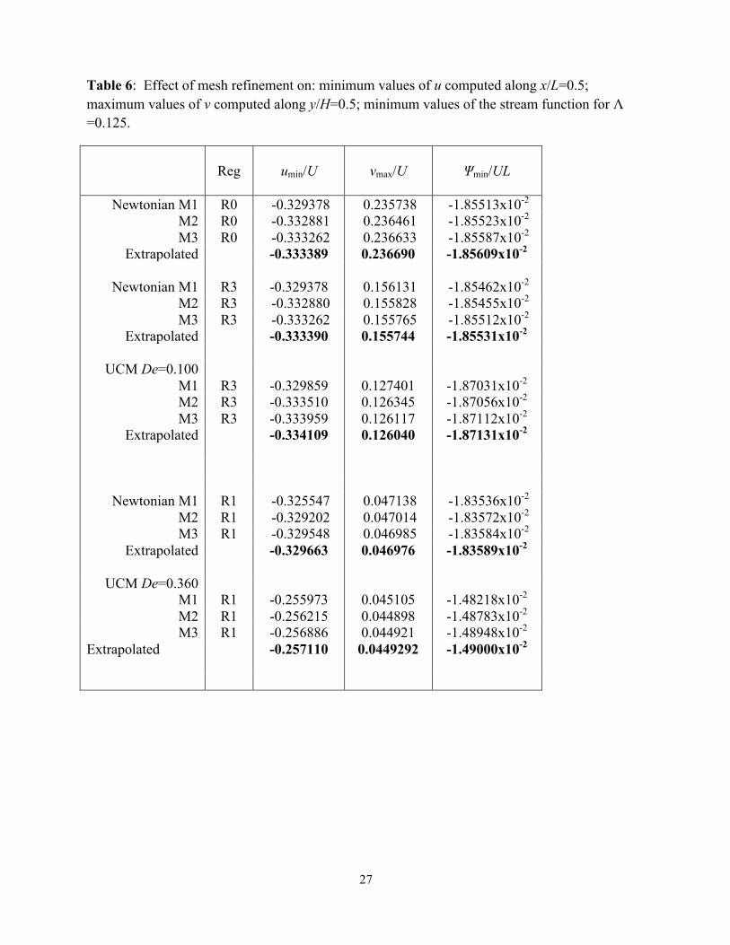
the accuracy of the numerical results are shown in Tables 5-7 for Λ=1, 0.125 and 4, respectively.
Overall, the difference between the results on the finest mesh and the extrapolated values –
obtained using Richardson’s technique [34] – are less than 0.2% for these quantities.

11
5. Creeping Newtonian flow
The streamline patterns for Newtonian flow – wall regularization R3 and mesh M3 – are shown
in Figure 3 for low aspect ratio (Λ < 1, Figure 3(a)) and high aspect ratio (Λ≥ 1 Figure 3(b)).
As discussed in the Introduction (and in [2]), for high aspect ratios the streamlines essentially
collapse in the top region of the cavities and the maximum absolute value of the stream function
– the variation of which with aspect ratio is shown in Figure 4 – becomes independent of aspect
ratio for Λ ≥ 1. For small aspect ratios the scenario is more complex although the asymptotic
limit when Λ → 0 does allow analytical expressions for the maximum stream function, velocity
and stress components to be derived (presented in Appendix A). Under these assumptions the
maximum absolute value of stream function is expected to vary linearly with the aspect ratio as
Λ=274min
ULψ , and this linear relationship is also included in Figure 4. Excellent agreement
between this analytical solution and computations can be seen with aspect ratios up to Λ=0.5,
especially for the unregularized and weakly regularized wall velocities (R0 and R3). In addition,
the intersection between that linear variation and the value 1.0|/| min =ULψ at high aspect ratio
shows that the “tall” cavities start at Λ≈0.7.
The effects of wall regularization are subtle, yet important. In the square cavity case, Λ=1,
regularizing using the standard polynomial function [18, 19] (R1 in our nomenclature) reduces
quantitatively the strength of the main recirculation, by about 16%, (in agreement with previous
studies [33]) but the qualitative effect on the streamlines (Figure 5) appears to be minor except
close to corners A and B, as might be expected. At the lower aspect ratios, however, there are
significant qualitative differences between the streamline patterns and the unregularized
streamlines are essentially straight over the middle 75% of the cavity. Changing the
regularization such that it better approximates the unregularized case, e.g. R3, essentially
increases the vortex strength back to its unregularized value (see Table 5 for example) and better
captures the streamline patterns (although close to the corners A and B differences are still
apparent – Figure 5). To better illustrate these effects, in Figure 6 we plot contours of the flow
type classifier. The flow-type parameter ξ is used to classify the flow locally, and here we use the
criterion proposed by Lee et al. [35], Ω
Ω
+
−≡DD
ξ ; where |D| and |Ω | represent the magnitudes of

12
the rate of deformation tensor and vorticity tensor, ( )DDD :21
= and ( )ΩΩΩ :21
= . As
such, ξ = 1 corresponds to pure extensional flow, ξ = 0 corresponds to pure shear flow and ξ = −1
corresponds to solid-body rotation flow.
As seen in Figure 6, the regularization of the lid velocity significantly affects the flow close to
the lid ends. Without regularization (R0), the flow close to the wall is mainly shear dominated.
However, the wall regularization induces a strong component of extensional flow close to
corners A and B due to the acceleration and deceleration of the fluid at these corners. As this
acceleration region decreases (R1→ R2 → R3) the region of extensional-dominated flow also
decreases and approaches the “true” lid-driven cavity flow field (R0).
Given the basic modification to the flow field induced by the regularization classically used for
viscoelastic fluids [18, 19], care must be taken when comparing regularized simulation results
with experimental results [9, 10, 17]. This issue is probably why Grillet et al. [16] implemented
a “leaky” boundary condition at corners A and B. In contrast here we attempt to tackle this
problem via modification of the classical regularization (R1).
6. Viscoelastic flow
6.1 Steady-state flow field
The addition of fluid elasticity induces changes to the flow pattern in the lid-driven cavity, and,
in particular, a breaking of fore-aft symmetry relative to the x/L=0.5 line. Figure 7 presents the
computed streamlines for Newtonian and viscoelastic fluid flow for different aspect ratios,
Λ=0.125, 0.25, 0.5 and 1. For the viscoelastic fluid flow, the cases illustrated correspond to the
highest De where steady flow is observed with regularization R3 (De=0.15). For the Newtonian
fluid the flow field is symmetric, as it must be in creeping flow, due to the linearity of the Stokes
flow.
The large normal stresses that are generated for the viscoelastic fluid as De increases are
advected in the downstream direction leading to an increase of the flow resistance, and to

13
compensate for this effect the eye of the recirculation region progressively shifts in the upwind
direction - towards corner A as illustrated in Figure 1 - breaking the symmetry observed for
Newtonian fluids. This effect is in excellent agreement with experimental observations for
Boger fluids [9]. The increase of the normal stresses with increasing De, and concomitant higher
flow resistance, induces a decrease in the strength of the main recirculating flow (the flow closest
to the lid), i.e. a reduction of || minψ as illustrated in Figure 8 for different aspect ratios as a
function of De (for three different lid velocity regularizations). This effect is akin the vortex
suppression by elasticity seen in many other flow situations, for example in sudden expansion
geometries, and entails the coupling of elastic hoop stresses and curved streamlines (as discussed
below in Section 6.2). For the lower aspect ratio cases and the regularizations (R2 and R3) closer
to the unregularized situation (R0), the streamlines in a large region about the central section of
the cavity are straight, with curvature confined to a small region near the lateral walls (see eg.
Figure 4 top), so the mechanism of the vortex suppression should be less effective. Indeed, we
find in Figure 8 a slight initial increase, although small (about 1-2 %) of the vortex intensity
with elasticity for the lower curve cases of Λ=0.125 and 0.25 with regularizations R2 and R3,
which we interpret as resulting from straighter streamlines.
Similarly to the Newtonian fluid flow case, the intensity of recirculating fluid increases with
aspect ratio up to Λ=1, before saturating, and further increases of Λ have a negligible effect on
|| minψ as shown by the data collapse for Λ≥1. The additional recirculation zones that are formed
as Λ increases, e.g. shown for a Newtonian fluid in Figure 5, are significantly weaker, having a
negligible effect on || minψ . With the regularization R1 (black symbols), since the lid-velocity
profile is smoother and has a lower average velocity relative to the R3 regularization, the
maximum value of the stream function magnitude is also lower and higher Deborah numbers can
be achieved prior to the onset of a purely-elastic instability, which we discuss next.
6.2 Onset and scaling of a purely-elastic instability
The critical conditions for the onset of a purely-elastic instability are presented in Figure 9, both
in terms of a critical reciprocal Weissenberg number (1/Wicr) and a Deborah number (Decr) as a
function of aspect ratio, using three different lid regularizations (R1-R3), computed using mesh

14
M3. The critical condition is identified when a steady-state solution can no longer be obtained:
thus the purely-elastic instability, in all cases examined here, gives rise to a time varying flow in
agreement with experimental observations [10]. We confirmed that this critical condition is
independent of the time-step used in the time-matching algorithm.
For a given level of wall regularization, the flow instabilities for different aspect ratios occur
approximately at a constant Deborah number, e.g. for R1 the values are within De = 0.625 ±
0.050. Consequently, 1/Wicr varies linearly with aspect ratio, with 1/Wicr = 1.60Λ for
regularization R1. As the regularization is weakened, and the forcing better approximates the
“true” unregularized case i.e. R1 → R2 → R3, the critical De (or Wi) decreases significantly
from 0.63 (R1) to 0.33 (R2) to 0.18 (R3). Thus the precise regularization used can decrease the
critical De to about one third. The use of an average wall velocity ( LxuUL
∫= 0d ), instead of
the peak velocity U, reduces these differences in critical value slightly (to about half). The use
of a more appropriate characteristic time, based on the distance over which the lid velocity
grows, to define De* and Wi* as described in Section 3, is much better able to collapse the
critical conditions as shown in Figure 9(b). For the two weakest forms of regularization (R2 and
R3) this practically collapses the critical values. If this scaling is representative of the
controlling dynamics it would imply that the unregularized lid is unstable for vanishingly small
elasticities (given the infinite acceleration, or zero acceleration time, for a fluid element to go
from rest to velocity U, or equivalently De*→∞), but as shown in Section 3, numerically De* is
finite since the mesh elements do not have zero length.
Figure 10(a) presents the contours of the Pakdel-McKinley criterion
( ) ( )γητλ !011 //ℜ= uMcrit [8,12], (where 11τ is the tensile stress in the local streamwise
direction, γ! is the local shear rate and ℜ is the local streamline radius of curvature), for
Λ=0.25, 0.5, 1, 2 and 4 for the highest steady De. The maximum values of Mcrit are of the same
order as observed in previous studies, between 3 and 4 [12], namely 3.6
(Λ=0.25), 3.9 (Λ=0.5), 3.5 (Λ=1, 2 and 4). These critical M values are located near the
downstream corner, where large normal stresses generated on approaching corner B are advected
into a region of high streamline curvature.

15
Finally, contours of the flow type parameter are presented in Figure 10 (b), at the highest stable
De for which the flow remains steady for Λ=0.125 and 1, for both regularizations R1 and R3. For
Λ=1, the flow is mainly rotational close to the main vortex centre, shear dominated close to the
lid and highly extensional near the top corners in a direction at 45º and in the lower part of the
cavity, albeit here the deformation rates and hence stresses are always modest. For Λ=0.125, the
flow is mainly shear dominated close to the lid and bottom wall and highly extensional close to
the corners and along a thin strand at y/H ≈ 1/3.
5. Conclusions
Viscoelastic creeping flow in a lid-driven cavity was analysed numerically using a finite-volume
numerical methodology in combination with the log-conformation technique. The effects of
aspect ratio, strength of elasticity via the Deborah/Weissenberg numbers and, in contrast to
previous studies, the effect of regularization type for the lid velocity were investigated. As
discussed in the introduction and, as observed in previous studies for Newtonian fluids, the
streamlines essentially collapse and the stream function becomes independent of aspect ratio, for
Λ≥1. For low aspect ratios, the maximum value of the stream function magnitude agrees with a
simple parallel-flow approximation analytical solution.
The effect of elasticity on the steady flow characteristics was elucidated, including the
experimentally-observed shift of the main vortex centre in the direction of the upstream corner
(A) and the breaking of fore-aft symmetry with increasing elasticity. Increasing the elasticity
was also found to reduce the flow strength induced by the lid. The critical conditions for the
onset of purely-elastic flow instabilities were characterized by plotting 1/Wicr (and Decr) as a
function of aspect ratio. The value of the Pakdel- McKinley criterion [12] at the critical
conditions was similar to previous studies, between 3 and 4. In accordance with the
experimental results of Pakdel and McKinley [8,10,12], we find a linear scaling of reciprocal
Weissenberg number with aspect ratio, corresponding to a constant Deborah number, the
numerical value of which is dependent on the wall regularization used. By introducing a
modified Deborah number, based on an average acceleration time for the flow adjacent to the lid
to accelerate from u=0 to u=U, a reasonable collapse for the various Λ is achieved. The flow-

16
type parameter was also computed to characterize the different regions of the lid-driven cavity
flow. Further studies are required to investigate more closely the generated time-dependent
flows.
Acknowledgements. RGS and MAA acknowledge funding from the European Research
Council (ERC) under the European Union's Seventh Framework Programme (ERC Grant
Agreement n. 307499). RJP acknowledges funding for a “Fellowship in Complex Fluids and
Rheology” from the Engineering and Physical Sciences Research Council (EPSRC, UK) under
grant number (EP/M025187/1). AMA acknowledges Fundação para a Ciência e a Tecnologia
(FCT) for financial support through the scholarship SFRH/BPD/75436/2010. AM acknowledges
support from the UK Engineering and Physical Sciences Research Council (EP/I004262/1).
Research outputs generated through the EPSRC grant EP/I004262/1 can be found
at http://dx.doi.org/10.7488/ds/1330.
17
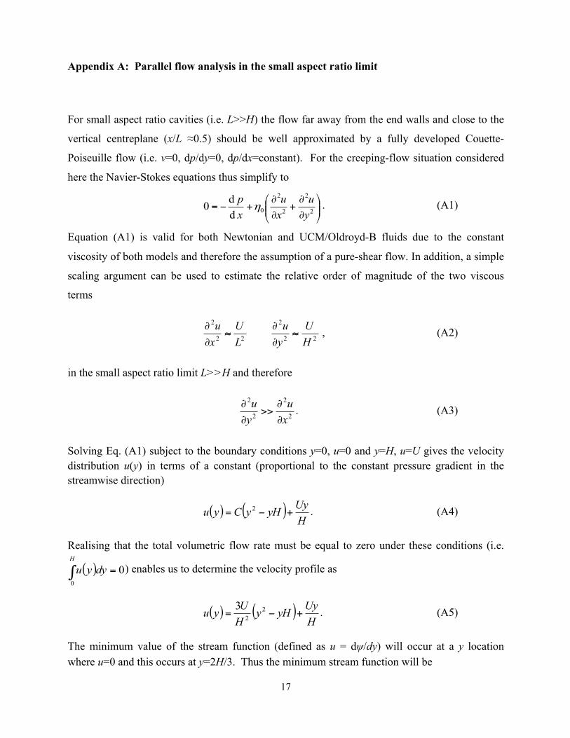
Appendix A: Parallel flow analysis in the small aspect ratio limit
For small aspect ratio cavities (i.e. L>>H) the flow far away from the end walls and close to the
vertical centreplane (x/L ≈0.5) should be well approximated by a fully developed Couette-
Poiseuille flow (i.e. v=0, dp/dy=0, dp/dx=constant). For the creeping-flow situation considered
here the Navier-Stokes equations thus simplify to
⎟⎟⎠
⎞⎜⎜⎝
⎛
∂
∂+
∂
∂+−= 2
2
2
2
0dd0
yu
xu
xp
η . (A1)
Equation (A1) is valid for both Newtonian and UCM/Oldroyd-B fluids due to the constant
viscosity of both models and therefore the assumption of a pure-shear flow. In addition, a simple
scaling argument can be used to estimate the relative order of magnitude of the two viscous
terms
22
2
22
2
HU
yu
LU
xu
≈∂
∂≈
∂
∂ , (A2)
in the small aspect ratio limit L>>H and therefore
2
2
2
2
xu
yu
∂
∂>>
∂
∂ . (A3)
Solving Eq. (A1) subject to the boundary conditions y=0, u=0 and y=H, u=U gives the velocity distribution u(y) in terms of a constant (proportional to the constant pressure gradient in the streamwise direction)
( ) ( )HUyyHyCyu +−= 2 . (A4)
Realising that the total volumetric flow rate must be equal to zero under these conditions (i.e.
( ) 00
=∫H
dyyu ) enables us to determine the velocity profile as
( ) ( )HUyyHy
HUyu +−= 22
3 . (A5)
The minimum value of the stream function (defined as u = dψ/dy) will occur at a y location where u=0 and this occurs at y=2H/3. Thus the minimum stream function will be

18
UH274
min −=ψ . (A6)
The stream function can be normalized using UL and introducing the aspect ratio (Λ=H/L) gives
Λ−=274min
ULψ . (A7)
We can also use the velocity distribution to estimate the maximum dimensionless shear stress on the lid (=η0(du/dy)(y=H))
Λ=4
0ULxy
η
τ, (A8)
and also the maximum dimensionless axial normal stress
βητ
Λ=
WiULxx 32
0
. (A9)

19
References
[1] P.N. Shankar and M.D. Deshpande, Fluid mechanics in the driven cavity, Ann. Rev. Fluid
Mech., 32 (2000) 93–136.
[2] P.N. Shankar, The eddy structure in Stokes flow in a cavity, J. Fluid Mech., 250 (1993)
371–83.
[3] H.K. Moffatt, Viscous and resistive eddies near a sharp corner, J. Fluid Mech., 18 (1964)
1-18.
[4] M. Sahin and R.G. Owens, A novel fully implicit finite volume method applied to the lid-
driven cavity problem- Part I: High Reynolds number flow calculations, Int. J. Num. Meth.
Fluids, 42 (2003) 57-77.
[5] C. K. Aidun, A. Triantafillopoulos, and J. D. Benson, Global stability of lid-driven cavity
with throughflow: Flow visualization studies, Phys. Fluids A, 3 (1996) 2081.
[6] O. Botella and R. Peyret, Benchmark spectral results on the lid-driven cavity flow,
Computers & Fluids, 27(4), (1998) 421-433.
[7] E. Erturk, T.C. Corke and C. Gokcol, Numerical solutions of 2-D steady incompressible
driven cavity flow at high reynolds numbers, Int. J. Num. Meth. Fluids, 48 (2005), 747-
774.
[8] P. Pakdel and G.H. McKinley, Elastic instability and curved streamlines, Phys. Rev.Lett.,
77(12) (1996) 2459-2462.
[9] P. Pakdel, S.H. Spiegelberg and G.H. McKinley, Cavity flow of viscoelastic fluids: two
dimensional flows, Phys. Fluids, 9 (1997) 3123-3140.
[10] P. Pakdel and G.H. McKinley, Cavity flows of elastic liquids: purely elastic instabilities,
Phys. Fluids, 10(5) (1998) 1058-1070.
[11] D. V. Boger, A highly elastic constant-viscosity fluid, J. Non-Newt. Fluid Mech., 3 (1977)
87-91.
[12] G.H. McKinley, P. Pakdel and A. Oztekin, Geometric and Rheological Scaling of Purely
Elastic Flow Instabilities, J. Non-Newt. Fluid Mech., 67 (1996) 19-48.
[13] A.N. Morozov and W. van Saarloos, An introductory essay on subcritical instabilities and
the transition to turbulence in visco-elastic parallel shear flows. Physics Reports, 447(3),
(2007) 112-143.

20
[14] M.A. Fardin, D. Lopez, J. Croso, G. Grégoire, O. Cardoso, G.H. McKinley and S. Lerouge,
Elastic turbulence in shear banding wormlike micelles. Physical Review Letters, 104(17),
(2010) 178303.
[15] J. Zilz, R.J. Poole, M.A. Alves, D. Bartolo, B. Levaché and A. Lindner, Geometric scaling
of a purely elastic flow instability in serpentine channels, J. Fluid Mech., 712, (2012) 203-
218.
[16] A.M. Grillet, B. Yang, B. Khomami and E.S.G. Shaqfeh, Modelling of viscoelastic lid-
driven cavity flows using finite element simulations, J. Non-Newt. Fluid Mech., 88 (1999)
99-131.
[17] A.M. Grillet, E.S.G. Shaqfeh and B. Khomami, Observations of elastic instabilities in lid-
driven cavity flow, J. Non-Newt. Fluid Mech., 94 (2000) 15-35.
[18] R. Fattal and R. Kupferman, Time-dependent simulation of viscoelastic flows at high
Weissenberg number using the log-conformation representation. J. Non-Newt. Fluid
Mech., 126 (2005) 23–37.
[19] T.W. Pan, J. Hao and R. Glowinski, On the simulation of a time-dependent cavity flow of
an Oldroyd-B fluid, Int. J. Num. Meth. Fluids, 60 (2009) 791-808.
[20] F. Habla, M. W. Tan, J. Haßlberger and O. Hinrichsen, Numerical simulation of the
viscoelastic flow in a three-dimensional lid-driven cavity using the log-conformation
reformulation in OpenFOAM, J. Non-Newt. Fluid Mech. 212 (2014), 47-62.
[21] R. Comminal, J. Spangenberg and J. H. Hattel, Robust simulations of viscoelastic flows at
high Weissenberg numbers with the streamfunction/log-conformation formulation, J. Non-
Newton. Fluid Mech. 223(2015), 37-61.
[22] F.P. Martins, C.M. Oishi, A.M. Afonso and M.A. Alves, A numerical study of the Kernel-
conformation transformation for transient viscoelastic fluid flows. J. Comp. Physics, 302,
(2015) 653-673.
[23] S. Dalal, G. Tomar, P. Dutta, Numerical study of driven flows of shear thinning
viscoplastic fluids in rectangular cavities, J. Non-Newt. Fluid Mech., doi:
10.1016/j.jnnfm.2016.01.009. [24] K. Yapici, B. Karasozen and Y. Uludag, Finite volume simulation of viscoelastic laminar
flow in a lid-driven cavity, J. Non-Newt. Fluid Mech., 164 (2009) 51-65.
[25] E. Mitsoulis and Th. Zisis, Flow of Bingham plastics in a lid-driven square cavity, J. Non-
Newt. Fluid Mech. 101 (2001), 173-180.

21
[26] J. Zhang, An augmented Lagrangian approach to Bingham fluid flows in a lid-driven
square cavity with piecewise equal-order finite elements, Comp. Methods Appl. Mech.
Engrg. 199 (2010) 3051-3057.
[27] J.G. Oldroyd, On the formulation of rheological equations of state, Proc. Roy. Soc. London
A, 200 (1950) 523-541.
[28] R. Fattal and R. Kupferman, Constitutive laws of the matrix-logarithm of the conformation
tensor, J. Non-Newt. Fluid Mech., 123 (2004), 281-285.
[29] A. Afonso, P.J. Oliveira, F.T. Pinho and M.A. Alves, The log-conformation tensor
approach in the finite-volume method framework, J. Non-Newt. Fluid Mech., 157 (2009)
55–65.
[30] P.J. Oliveira, F.T. Pinho and G.A. Pinto, Numerical simulation of non-linear elastic flows
with a general collocated finite-volume method, J. Non-Newt. Fluid Mech., 79 (1998) 1-
43.
[31] M.A. Alves, P.J. Oliveira and F.T. Pinho, A convergent and universally bounded
interpolation scheme for the treatment of advection, Int. J. Num. Meth. Fluids, 41 (2003)
47-75.
[32] J.P. van Doormal and G. D. Raithby, Enhancements of the SIMPLE method for predicting
incompressible fluid flows, Num. Heat Transfer, 7 (1984) 147-163.
[33] P.J. Oliveira, Viscoelastic Lid-Driven Cavity Flows, Métodos Numéricos e
Computacionais em Engenharia, CMNE CILAMCE (2007) Ed. J César de Sá et al., Pub.
APMTAC/FEUP (ISBN 978-972-8953-16-4).
[34] J.H. Ferziger and M. Peric, Computational methods for fluid dynamics, Springer 3ed, 2001
[35] J.S. Lee, R. Dylla-Spears, N-P. Teclemariam and S. J. Muller, Microfluidic four-roll mill
for all flow types, Appl. Phys. Lett. 90 (2007) 074103.

22
Tables
Table 1: Previous numerical studies concerned with lid-driven cavity flow of constant viscosity viscoelastic fluids.
Reference Aspect ratios
Constitutive equation
Wi Regularization Notes
Grillet et al. [16]
0.5, 1.0, 3.0
FENE-CR
L2=25, 100, 400
≤ 0.24 Leakage at corners A and B
FE
Fattal and Kupferman
[18]
1.0 Oldroyd-B, β=0.5
1.0, 2.0, 3.0 and 5.0
u(x)=16Ux2(1-x)2
FD, Log conformation
technique
Pan et al. [19]
1.0 Oldroyd-B, β=0.5
0.5, 1.0 u(x)=16Ux2(1-x)2
FE, Log conformation
technique
Yapici et al.
[24]
1.0 Oldroyd-B,
β=0.3
≤ 1.0 No FV, First-order
upwind
Habla et al. [20]
1.0 Oldroyd-B, β=0.5
0 ≤ 2 u(x,z)=128[1+tanh8(t-1/2]x2(1-x)2 z2(1-z2)
FV, 3D, Log conformation
technique, CUBISTA
Comminal et al. [21]
1.0 Oldroyd-B,
β=0.5
0.25≤10 u(x)=16Ux2(1-x)2 FD/FV, Log- conformation,
stream function
Martins et al. [22]
1.0 Oldroyd-B, β=0.5
0.5, 1.0, 2.0 u(x)=16Ux2(1-x)2
FD, Kernel-conformation
technique
Dalal et al. [23]
1.0 Oldroyd-B, β=0.5
1.0 u(x)=16Ux2(1-x)2
FD, Symmetric square root
FE: Finite-element method; FD: Finite-difference method; FV: Finite-volume method

23
Table 2: Main characteristics of the computational meshes (NC=number of cells)
Aspect ratio
Λ=H/L
M1 M2 M3 M4
Δxmin/L=
Δymin/L
NC Δxmin/L=
Δymin/L
NC Δxmin/L=
Δymin/L
NC Δxmin/L=
Δymin/L
NC
0.125 0.0012 4125 0.0006 16779 0.0003 67671
0.25 0.0012 6765 0.0006 27307 0.0003 108405
0.5 0.0025 3403 0.0012 13695 0.0006 54285
1.0 0.005 1681 0.0024 6889 0.0012 27225 0.0006 108241
1.5 0.005 2255 0.0024 9213 0.0012 36795
2.0 0.005 2747 0.0024 11039 0.0012 43725
3.0 0.005 3731 0.0024 15189 0.0012 60225
4.0 0.005 4797 0.0024 19339 0.0012 76725

24
Table 3: Comparison of current results with literature values for Newtonian fluids, for creeping flow, Re→0. Unregularized lid (R0), Λ =1: minimum values of u computed along x/L=0.5; maximum values of v computed along y/H=0.5; minimum values of the stream function and the corresponding coordinates xmin/L, ymin/H of the centre of the recirculation.
Reference umin/U vmax/U Ψmin/UL xmin/L, ymin/H
Botella and Peyret [6]
-0.100076
Grillet et al. [16] -0.099931 0.5000, 0.7643
Mitsoulis and Zisis [25] -0.0995 0.5000, 0.7625
Sahin and Owens [4] -0.207754 0.186273 -0.100054 0.5000, 0.7626
Yapici et al. [24] -0.207738 0.184427 -0.100072 0.5000, 0.7651
Zhang [26] -0.0996 0.5000, 0.7645
Habla et al. [20] (*)3D 0.500, 0.763 (*)
Current study M4
Extrapolated
-0.207719
-0.207762
0.184425
0.184449
-0.100063
-0.100074
0.5000, 0.7647
0.5000, 0.7644

25
Table 4: Comparison of current results with literature values for viscoelastic fluids, Oldroyd-B model, β = 0.5, regularization R1, Λ=1, Re =0.
Reference
De MAX(ln(τxx/(η0U/L))
at x=0.5) Ψmin/UL xmin/L, ymin/H
Pan et al. [19] 0.5 ≈5.5 -0.0700056 0.469, 0.798
Current work M3 0.5 5.34 -0.0697524 0.464, 0.797
Current work M4 0.5 5.51 -0.0697717 0.466, 0.800
Current work extr. 0.5 5.57 -0.0697781 0.467, 0.801
Pan et al. [19] 1.0 ≈8.6 -0.0638341 0.439, 0.816
Current work M3 1.0 7.22 -0.0618784 0.433, 0.821
Current work M4 1.0 7.80 -0.0619160 0.434, 0.816
Current work extr. 1.0 7.99 -0.0619285 0.434, 0.814
Dalal et al. [23]
( Re = 1.0)
1.0 - -0.06141 0.432, 0.818

26
Table 5: Effect of mesh refinement on: minimum values of u computed along x/L=0.5; maximum values of v computed along y/H=0.5; minimum values of the stream function for Λ =1.
Reg
umin/U
vmax/U Ψmin/UL
Newtonian M1 R0 -0.205678 0.183351 -9.93048x10⁻² M2 R0 -0.207204 0.184001 -9.98509x10⁻² M3 R0 -0.207589 0.184353 -1.00028x10⁻¹ M4 R0 -0.207719 0.184425 -1.00063x10⁻¹
Extrapolated
-0.207762
0.184449 -1.00074x10⁻¹
Newtonian M1 R3 -0.205654 0.183584 -9.93471x10⁻² M2 R3 -0.207129 0.184158 -9.98783x10⁻² M3 R3 -0.207494 0.184496 -1.00051x10⁻¹ M4 R3 -0.207621 0.184566 -1.00084x10⁻¹
Extrapolated -0.207663 0.184589 -1.00095x10⁻¹
UCM De=0.1 M1 R3 -0.198595 0.176940 -9.67456x10⁻²
M2 R3 -0.200029 0.177549 -9.72368x10⁻² M3 R3 -0.200508 0.177916 -9.73744x10⁻² M4 R3 -0.200609 0.177995 -9.74221x10⁻²
Extrapolated
-0.200643 0.178021 -9.74380x10⁻²
Newtonian M1 R1 -0.167654 0.146202 -8.31277x10⁻² M2 R1 -0.168682 0.146625 -8.35121x10⁻² M3 R1 -0.168842 0.146698 -8.36359x10⁻² M4 R1 -0.168885 0.146725 -8.36574x10⁻²
Extrapolated -0.168899 0.146735 -8.36646x10⁻²
UCM De=0.4 M1 R1 -0.116698 0.104745 -5.96625x10⁻² M2 R1 -0.117251 0.105013 -5.99104x10⁻² M3 R1 -0.117398 0.105118 -5.99880x10⁻² M4 R1 -0.117412 0.105109 -5.99925x10⁻²
Extrapolated -0.117417 0.105106 -5.99940x10⁻²
27
Table 6: Effect of mesh refinement on: minimum values of u computed along x/L=0.5; maximum values of v computed along y/H=0.5; minimum values of the stream function for Λ =0.125.
Reg
umin/U
vmax/U Ψmin/UL
Newtonian M1 R0 -0.329378 0.235738 -1.85513x10⁻² M2 R0 -0.332881 0.236461 -1.85523x10⁻² M3 R0 -0.333262 0.236633 -1.85587x10⁻²
Extrapolated -0.333389 0.236690 -1.85609x10⁻²
Newtonian M1 R3 -0.329378 0.156131 -1.85462x10⁻² M2 R3 -0.332880 0.155828 -1.85455x10⁻² M3 R3 -0.333262 0.155765 -1.85512x10⁻²
Extrapolated -0.333390 0.155744 -1.85531x10⁻²
UCM De=0.100
M1
R3
-0.329859
0.127401
-1.87031x10⁻² M2 R3 -0.333510 0.126345 -1.87056x10⁻²
M3 R3 -0.333959 0.126117 -1.87112x10⁻² Extrapolated
-0.334109 0.126040 -1.87131x10⁻²
Newtonian M1 R1 -0.325547 0.047138 -1.83536x10⁻² M2 R1 -0.329202 0.047014 -1.83572x10⁻² M3 R1 -0.329548 0.046985 -1.83584x10⁻²
Extrapolated -0.329663 0.046976 -1.83589x10⁻²
UCM De=0.360
M1
R1
-0.255973
0.045105
-1.48218x10⁻² M2 R1 -0.256215 0.044898 -1.48783x10⁻² M3 R1 -0.256886 0.044921 -1.48948x10⁻²
Extrapolated
-0.257110 0.0449292 -1.49000x10⁻²

28
Table 7: Effect of mesh refinement on: minimum values of u computed along x/L=0.5; maximum values of v computed along y/H=0.5; minimum values of the stream function for Λ =4.
Reg
umin/U
vmax/U Ψmin/UL
Newtonian M1 R0 -0.192048 3.80498x10⁻⁴ -9.98683x10⁻² M2 R0 -0.194012 3.82099x10⁻⁴ -1.00644x10⁻¹ M3 R0 -0.194708 3.82390x10⁻⁴ -1.00817x10⁻¹
Extrapolated -0.194940 3.82487x10⁻⁴ -1.00874x10⁻¹
Newtonian M1 R3 -0.191946 3.81280x10⁻⁴ -9.99168x10⁻²
M2 R3 -0.193858 3.82780x10⁻⁴ -1.00673x10⁻¹ M3 R3 -0.194552 3.83055x10⁻⁴ -1.00843x10⁻¹
Extrapolated
-0.194782 3.83147x10⁻⁴ -1.00900x10⁻¹
UCM De=0.12 M1 R3 -0.183001 3.61449x10⁻⁴ -9.59420x10⁻²
M2 R3 -0.184866 3.62997x10⁻⁴ -9.68424x10⁻² M3 R3 -0.185434 3.63281x10⁻⁴ -9.69867x10⁻²
Extrapolated -0.185623 3.63375x10⁻⁴ -9.70348x10⁻²

29
Figures
Figure 1: Schematic of lid-driven cavity (including representative streamlines for creeping Newtonian flow).
H
L
A B
C D x
y

30
Figure 2: Lid velocity profiles for different regularizations used in this work. The average velocities U*m (from x=0 to x=L*, where u=U) for each regularization are 0.533 for R1, 0.377 for R2 and 0.352 for R3.
0 0.2 0.4 0.6 0.8 10
0.25
0.5
0.75
1
1.25
x / L
u/U
R1
R2
R3
R0

31
(a)
(b)
Figure 3: Streamlines for Newtonian fluid flow using lid velocity regularization R3 and mesh
M3 (a) small aspect ratios (Λ < 1) (and zoomed region near the downstream corner) (b) large
aspect ratios (Λ ≥ 1) (and zoomed region near downstream corner).

32
Figure 4: Variation of the absolute value of the minimum normalised stream function with
aspect ratio for Newtonian fluid flow (regularizations R0, R1, R2 and R3) including the
analytical solution for the small aspect ratio limit.
0.00
0.02
0.04
0.06
0.08
0.10
0.12
0.14
0.16
0.0 1.0 2.0 3.0 4.0 5.0
|ψmin|/UL
Λ
R0 R1 R2 R3
- - |Ψmin|/UL =4/27Λ

33
Figure 5: Effect of lid velocity regularization (R0, R1, R3) on the computed streamlines for
aspect ratios Λ = 0.25, 1, 2 and 4, using mesh M3.

34
Figure 6: Flow type parameter for different lid velocity regularizations for Λ=1 and creeping flow of Newtonian fluids.

35
(a)
(b)
(c)
(d)
Figure 7: Effect of elasticity on streamlines using lid velocity regularization R3 and mesh M3
(a) Λ=0.125 (b) Λ=0.25, (c) Λ=0.50, and (d) Λ=1.00 .

36
Figure 8: Variation of absolute value of minimum dimensionless stream function with De for
various aspect ratios (Λ = 0.125, 0.25, 0.50, 1.00, 2.00, 4.00, with Mesh M3) and lid velocity
regularization (R1, R2 and R3).

37
(a)
(b)
Figure 9: Critical conditions for the onset of purely-elastic instability for different lid velocity
regularizations computed in mesh M3: (a) 1/Wicr and Decr versus aspect ratio; (b) 1/Wi*cr and
De*cr versus aspect ratio.
0.0
0.1
0.2
0.3
0.4
0.5
0.6
0.7
0.8
0.9
0.0
5.0
10.0
15.0
20.0
25.0
30.0
0.0 1.0 2.0 3.0 4.0 5.0
Decr
1/Wi cr
Λ
1/Wi(R1) 1/Wi(R2) 1/Wi(R3)De(R1) De(R2) De(R3)
cr
cr
cr
cr
cr
cr
0.0
0.2
0.4
0.6
0.8
1.0
1.2
0.0
1.0
2.0
3.0
4.0
5.0
6.0
7.0
8.0
0.0 1.0 2.0 3.0 4.0 5.0
De* c
r
1/Wi*
cr
Λ
1/Wi*(R1) 1/Wi*(R2) 1/Wi*(R3)De*(R1) De*(R2) De*(R3)
crcr
cr
cr
cr
cr

38
(a)
(b)
Figure 10: Nature of instability shown by contours of: (a) M parameter at critical De, for
regularization R1; (b) Flow type parameter ξ at critical De for Λ=0.125 and 1.0, regularizations
R1 and R3.