liebert - webbuilder.asiannet.com · the high density heat load in a computer room or other similar...
TRANSCRIPT

Deluxe System/3®
ENVIRONMENTAL CONTROL
TECHNICAL DATA MANUAL
K e e p i n g B u s i n e s s i n B u s i n e s sLiebert ®
®
ISO 9000
CERTIFIED
COMPANY
Floor Mounted, 60 HzNominal 6 thru 30 tons Air Cooled Water Cooled Glycol Cooled GLYCOOL

Sensitive Electronicsand Environmental Control...............................................................................................3
Liebert Technologyand Energy Efficiency.......................................................................................................6
Control Systems...............................................................................................................8
Standard Features/All Systems.....................................................................................................................10
Standard Features/Individual Systems.........................................................................................................12
Optional Features/Individual Systems.........................................................................................................14
Optional Features/All Systems.....................................................................................................................16
Air Cooled Data..............................................................................................................18
Water Cooled Data.........................................................................................................20
Glycol Cooled Data........................................................................................................22
Glycool Data...................................................................................................................24
Dimensional Data—Upflow Models...............................................................................26
Electrical Data—Upflow Models....................................................................................28
Dimensional Data—Downflow Models...........................................................................32
Electrical Data—Downflow Models................................................................................33
Dimensional/Electrical DataDrycoolers, Condensers, Pump Packages,Temperature/Humidity Recorder....................................................................................36
Guide Specifications/Compressorized Systems..............................................................................................38
Installation/Application Guidelines...................................................................................................45
Contents

Essential Environmental Controlfor Sensitive Electronics
Downflow Discharge
Upflow Discharge with Front ReturnProduct Model Information
Model Number Designation
DH 245 A - A A E I
DH = Downflow Nominal A = Air Cooled – = 2 Step A = 460/3/60 A = Advanced 0 = No Reheat 0 = NoDX Capacity in DX Microprocessor Humidifier
Thousand BTU/H
VH = Upflow DX W = Water U = 4 Step DX B = 575/3/60 G = Advanced E = Electric I = InfraredCooled Graphics Reheat Humidifier
G = Glycol C = 208/3/60Microprocessor
H = Hot Water G = Steam GridCooled Reheat Humidifer
DE = Downflow H = DX with D = 230/3/60 G = Hot Gas S = Steamwith Econ-o-coil Hot Gas Bypass Reheat Generating
Humidifier
VE = Upflow with 2 = 380/3/60 T = SteamEcon-o-coil Reheat
Upflow Discharge with Rear Return
3

For sensitive electronics,environmental control ismore than simple cooling.“Comfort” air conditioningsystems are designed forthe comfort of people, andsimply cannot provide thekind of environment requiredby high performance com-puter or communicationequipment.
Temperature ControlThe high density heat loadin a computer room or othersimilar application is beyondthe capacity of ordinary airconditioning systems.Sensitive electronics arebest maintained in a stableenvironment of 72°F ±2°F(22.2°C ±1°C). As computersand communications equip-ment generate large quantitiesof heat in small areas, six toten times the heat density ofnormal office space, the airconditioning system musthave more than just enoughcooling capacity. It must havethe precision to react quicklyto a drastic change in heatload and prevent widetemperature fluctuations.Something a large buildingsystem cannot do.
Dedicated, Precise Environmental Control...Essential for Sensitive Electronics
Humidity ControlThe electronic equipmentmust be protected fromboth internal condensationand static electricitydischarges. Maintaining thecorrect humidity level in theroom is just as important asmaintaining proper tempera-ture. Too high a humiditycould cause condensationwithin the electronic equip-ment and the potential forhardware damage. If humidityis too low, static electricitycould disrupt operation oreven shut down the electronicsystem. An ordinary buildingsystem cannot normally con-trol the environment withinthese boundaries.
Air VolumeComputers and othersensitive electronics requiregreater air volumes thanordinary air conditioningcan provide. Typical comfortsystems are designed to pro-vide between 300 and 400CFM (Cubic Feet per Minute),(500–700 CMH) per ton ofcooling. Computer systemsrequire between 500 and 600CFM (850–1020 CMH) perton. The high density heatload in a relatively small spacerequires more changes of airthan a less dense “comfort”application. While a normaloffice space requires only2 air changes per hour, aroom filled with electronicequipment requires up to30 changes per hour. Withoutproper air volume, hot spotsand temperature fluctuationscould develop within theroom. Also, greater air vol-umes provide the highersensible heat ratios requiredby electronic computerequipment.
Year Round OperationComfort conditioningsystems cannot be reliedupon 24 hours per day 365days per year. They aretypically designed to operateten hours per day, from Springto Autumn. Many “comfort”systems have no provision forwinter operation. A precisionenvironmental control systemis designed for operation attemperatures of up to –30°F(–34.4°C).
4

PrecisionThe environmental controlsystem must be able to senseand react to temperature andhumidity fluctuations far toosmall for building HVAC sys-tems to control.
The Deluxe System/3 iscapable of control to within±1°F (°C) and ±1% RH.With Liebert microprocessortechnology, it is possible tomaintain predictive controlover the environment. Byanalyzing the rate of changein temperature or the moisturecontent in the environment,the control system anticipateswhat is going to happen in theroom, not simply respond towhat has happened.
ReliabilityBecause electronic systemavailability is required 24hours a day, 365 days a year,the environmental controlsystem must meet the samedemands.
The Deluxe System/3 isdesigned with the highestquality components selectedfor their proven reliability.Microprocessor technologyadds automatic sequencing ofcomponents to even wear andextend service life. Automaticcleaning cycles can be pro-grammed to match local waterconditions. An alarm systemand self-diagnostics providerapid troubleshooting and canprevent a problem before itaffects the electronic equip-ment room environment.
Environmental ControlSystem Design
Energy EfficiencyConstant demand for preciseenvironmental control makesenergy efficiency all the moreimportant. A well-designedenvironmental control systemmakes the most of the energyit uses.
The Deluxe System/3 isdesigned for maximum energyefficiency. Beginning withsemi-hermetic compressors,the most reliable and energyefficient compressor available,Liebert adds an A–Frame coilthat can provide 60% of totalcapacity with only 1 of the 2compressors operating. Highlyefficient fan motors pull airthrough the coil, providing not
only better coil coverage,but reducing fan motorhorsepower requirements.A microprocessor controlsystem ties all the keyoperational componentstogether and responds tochanges in the room environ-ment in the most “intelligent”and energy conscious way.
UL ListedUnits are UL listed and CSA(NRTL-C) certified. NRTL-Cmeets both U.S. and Cana-dian government safetyrequirements, providing fast,hassle-free inspection andbuilding code approvals.
Desirable Feature Building Systems Deluxe System/3±1°F (°C)/1% RHHumidificationand DehumidificationLocal and Remote
Yes
20–95% based onASHRAE 52.1Yes
Yes
Comparison between comfort and precision systems
Precision
Humidity Control
MonitoringYear-RoundReliability
Air Filtration
Factory TestedIn-the-RoomDesign
Typically ±5°F (3°C)
Usually None
NoneNot designed forWinter Operation
Negligible
NoNo. CentrallyLocated
5

GLYCOOLA conventional glycol systemplus a second cooling coil totake advantage of colder out-door temperatures to reduceor eliminate compressoroperation.*
Liebert Technology andEnergy Efficiency
Liebert continues its worldleadership in precisionenvironmental systemsby providing maximumenergy efficiency withoutcompromising the accuracyand reliability demanded bysensitive electronics.
Liebert takes a no com-promise approach to environ-mental control system design.All enhancements to energyefficiency are designed toreduce operating time of keycomponents and increase theMean Time Between Failure.This is accomplished bytaking advantage of alternatesources of cooling withoutbeing dependent on theiravailability, or by reducingcompressor work load whenheat load in the conditionedspace is lower.
LiebertDrycooler
Glycol Circulating Pump Econ-o-coil
Motorized, 3-WayGlycool ControlValve
A-Frame Coil
Semi-HermeticCompressors
Glycol-CooledCondensers
Glycol Regulating Valve
*Downflow units shown. Also available in upflow configuration.6
No CompressorOperation Below35˚F (1.6˚C)
Pump
Glycool Unit
Drycooler
Econ-O-Coil
A/C Coil
Compressor
Indoor Fan
CondensorModulating Valve
35˚-65˚FReduced CompressorOperation(1.6˚-18.3˚C)
Normal OperationOver 65˚F (18.3˚C)

Four–StepCapacity control valveson each compressor (air,water, glycol or Glycoolsystems) and a speciallydesigned microprocessorreduce compressor capacityand increase efficiency duringlow heat-load periods inthe conditioned space.*
Air Cooled Condenser
Semi-HermeticCompressors
Hot Gas Lines
Liquid LinesMicroprocessorActuatedCapacity ControlValves
Dual Cooling SourceA conventional air or watercooled system plus a secondcooling coil to utilize a centralbuilding chiller and minimizecompressor operation.*
*Downflow units shown. Also available in upflow configuration.
Motorized Three-WayChilled Water RegulatingValve
Semi-HermeticCompressors
Second SourceChilled WaterSupply
A-Frame Coil
Econ-o-coil
Air Cooled Condenser
The Efficient Energy DollarPercent Room Load/Energy Consumption
95% ofMaximumRoom HeatLoad
45% ofMaximumRoom Heat
Step Four Step Three Step Two Step One
% of rated capacity achieved at eachstep
% of maximum compressor energyconsumption required
Data based on DH 199 AU and outdoorambient at 35°C (95°F).
100%100%
88%
75% 76%
50%
38%
25%
Air Cooled System Shown
7

Local Monitoring Systems
8
Advanced Microprocessor (AM)Control System Backlit 4 x 20 LCD
Two levels of microprocessorcontrol systems are availableproviding precise control andmonitoring of the criticalspace. The AdvancedMicroprocessor is standard,and the Advanced Micropro-cessor w/Graphics is optional.The main control fuctions aresimilar for both controls:
ControlThe user must enter a3-digit password beforemaking changes.
• Temperature Setpoint 65-85°F (18-29°C)• Temperature Sensitivity +1-10°F (0.6-5.6°C)• Humidity Setpoint 20-80% R.H.• Humidity Sensitivity 1-30% R.H.• High Temperature Alarm 35-90°F (2-32°C)• Low Temperature Alarm 35-90°F (2-32°C)• High Humidity Alarm 15-85% R.H.• Low Humidity Alarm 15-85% R.H.* Consult factory if you need to control at either end of this range.
Control TypeFactory set-up for IntelligentControl which uses “fuzzylogic” and “expert systems”methods. Proportional andTunable PID are user select-able options.
Internal SystemControl• Compressor short cycle control. Prevents compres- sor short-cycling and needless compressor wear.• Compressor sequencing. This feature monitors both stages of cooling and changes the lead/lag sequence each time the compressors are activated. This not only balances run time but compressor starts as well. This prevents short cycling and increases com- pressor life.
• System auto restart. The auto restart feature will automatically restart the system after a power failure. Time delay is programmable.• Sequential Load Activa- tion. On initial start-up or restart after power failure, each operational load is sequenced to minimize total inrush current.• Hot Water / Econ-o-coil Flush Cycles. Hot water reheat coils and Econ-o-coils are periodi- cally flushed to prevent a build-up of contaminants.• Temperature/Humidity Sensor Calibration. The sensors may be calibrated from the front monitor panel to insure that all units in the room are similarly calibrated, assuring greater precision.
Monitoring• Normal display includes present room tempera- ture and humidity, active functions (cooling, heat- ing, dehumidifying), and any alarms.• Operating status displays each control operation in percent.• Read analog inputs func- tion. Displays the present values of up to four ana- log inputs.
Diagnostics• Input diagnostics. Reviews inputs to the control system.• Control board diagnos- tics. Initiates a self-test of the control system.• Output diagnostics. Tests major compo- nents by turning them on and off from the control panel. Includes: main fan, compressor, liquid line solenoid valve, hot gas bypass valve, chilled water or chilled glycool valve, R-5 relay, reheat, hot water reheat valve,
humidifier, humidifier make-up valve, and common alarm.
Logging• Alarm history log. The Advanced Microprocessor displays the 10 most recent alarms. The Advanced Microprocessor with Graphics displays the most recent 60 alarms. Both provide a time and date stamp for each event.• Run time log. Displays run time and hours for major components (also allows reset of run hours) includ- ing compressors, glycool, fan, humidifier, and reheat.
Alarms• Humidifier problem• High head pressure• Change filter• Loss of air flow• High temperature• Low temperature• High humidity• Low humidity• Compressor overload (opt)• Main fan overload (opt)• Low suction pressure• Short cycle• Loss of power• Custom alarm (choose up to 4) • Water under floor • Smoke detected • Standby GC pump on • Loss of water flow • Standby unit on • User customized text

Optional Advanced Microprocessorw/Graphics (AG) Control SystemBacklit 240 x 128 dot matrix graphics display
9
OpenComms-NICThe OpenComms NetworkInterface Card (NIC) providesEthernet connectivity forLiebert equipment.Operating status and alarmsare communicated via thenetwork to external systemsutilizing industry-standardopen protocols.
The following protocols aresupported:
• SNMP v1, v2c• HTTP v1.1(web)
OpenComms OC-DOInterface Card provides 16discrete outputs, correspond-ing to status and majoralarm conditions. TheseForm-C contact-closuresprovide a straightforwardmeans to tie units to BMSCo. (Building ManagementSystems), I/O or alarm pan-els, and autodialer devices.
Dry contact monitors—RCM4, RCM8CELEDs display customizedalarm indication for any drycontact input, includingalarms for Liebert environ-mental, power and UPSsystems. RCM4 monitors anddisplays four dry contactpoints. The RCM8CE moni-tors and displays eight drycontacts; it can communi-cate with Liebert SiteScan,and also has modem dial-upcapabilities.
Single unit remotemonitoring—MR1Operating parameters for asingle environmental unit areselected with push-buttonsand displayed on an LCDscreen. This user-friendlysystem provides remotemonitoring and alarm warn-ing, for complete statusupdates.
The runtime screen provides datain either tabular or easy-to-readgraphic formats.
Histograms–historical depictions–oftemperature or humidity can bedisplayed on the screen for anal-ysis. This is especially helpful intracking the environmental factorsof an alarm.
If you have a Liebert water detectionsystem in the room, the display canprovide a floorplan for fast location oftrouble spots.
Some of the Optional Views withAdvanced Graphics:
In addition to LocalMonitoring, the followingoptional remote monitoringsystems are available:
Site ScanSiteScan is a monitoringsolution for critical environ-ments that utilize afacility-view approach. Thesystem enables communica-tions from Liebert environ-mental and power units -- aswell as many other pieces ofanalog or digital equipment-- to a front end softwarepackage which providesmonitoring, control andalarm management.SiteScan monitoring givesyou decision-making powerto effectively manage theequipment that is critical toyour business. Designedwith flexibility for large,complex systems as well assmaller single-site facilities,the Liebert SiteScan line ofproducts can provide real-time status and alarms.
SiteLinkThe microprocessor-basedmodule provides two-waycommunication betweenexisting building managementsystem and up to 12 Liebertunits via MODBUS or BACnet.
Remote Monitoring Systems
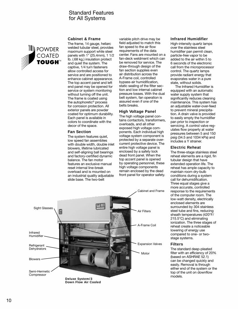
Cabinet & FrameThe frame, 14 gauge, heliarcwelded tubular steel, providesmaximum support while steelpanels with 1" (25.4mm), 1 1/2lb. (.68 kg.) insulation protectand quiet the system. Thecaptive, 1/4 turn fastenersallow controlled access forservice and are positioned toenhance cabinet appearance.The top accent panel and leftend panel may be opened forservice or system monitoringwithout turning off the unit.The frame is coated usingthe autophoretic® processfor corrosion protection. Allexterior panels are powdercoated for optimum durability.Each panel is available incolors to coordinate with thedecor of the space.
Fan SectionThe system features quiet,low speed fan assemblieswith double width, double inletblowers, lifetime lubricatedand self-aligning ball bearingsand factory-certified dynamicbalance. The fan motorfeatures an exclusive manualreset internal line-breakoverload and is mounted onan industrial quality adjustableslide base. The two-belt
Standard Featuresfor All Systems
variable pitch drive may befield adjusted to match thisfan speed to the air flowrequirements of the datacenter. Fans are mounted on afan-deck weldment which canbe removed for service. Thedraw-through design of thefan section supplies evenair distribution across theA-Frame coil, controlledbypass-air humidification,static sealing of the filter sec-tion and low internal cabinetpressure losses. With the dualbelt system, fan operation isassured even if one of thebelts breaks.
High Voltage PanelThe high voltage panel con-tains contactors, transformers,overloads, and all otherexposed high voltage com-ponents. Each individual highvoltage system component isprotected by a separate over-current protective device. Theentire high voltage panel isenclosed by a safety lockdead front panel. When thetop accent panel is openedby operating personnel, thesehigh voltage componentsremain enclosed by the deadfront panel for operator safety.
Infrared HumidifierHigh-intensity quartz lampsover the stainless steelhumidifier pan permit clean,particle-free vapor to beadded to the air within 5 to6 seconds of the electroniccall from the microprocessorcontrol. The quartz lampsprovide radiant energy thatevaporates water in a purestate, without solids.
The Infrared Humidifier isequipped with an automaticwater supply system thatsignificantly reduces cleaningmaintenance. This system hasan adjustable water-over-feedto prevent mineral precipita-tion. A drain valve is providedto easily empty the humidifierpan prior to inspection orservicing. A control valve reg-ulates flow property at waterpressures between 5 and 150psig (34.5 and 1034 kPa) andincludes a Y strainer.
Electric ReheatThe three-stage stainless steelreheat elements are a rigid, fintubular design that haveextended operation life. Thereheat has ample capacity tomaintain room dry-bulbconditions during a systemcall for dehumidification.Three equal stages give amore accurate, controlledresponse to the requirementsof the computer room. Thelow-watt density, electricallyenclosed elements aresurrounded by 304 stainlesssteel tube and fins, reducingsheath temperatures (420°F/215.5°C) and eliminatingionization. The three stages ofreheat create a noticeablelowering of energy usecompared to one- or two-stage systems.
FiltersThe standard deep-pleatedfilter with an efficiency of 20%(based on ASHRAE 52.1)can be changed quickly andeasily. Removal is througheither end of the system or thetop of the unit on downflowmodels.
Motor
Sight Glasses
InfraredHumidifier
RefrigerantDehydrators
Blowers
Semi-HermeticCompressor
Cabinet and Frame
Air Filters
A-Frame Coil
Expansion Valves
Deluxe System/3Down Flow Air Cooled
10

Semi-HermeticCompressorsTwo rugged cast-iron semi-hermetic compressors incor-porate specific elementsdesigned to maximize oper-ating efficiency and facilitatefield servicing. The compres-sors, mounted on vibrationisolators, have built in over-loads, oil sight glass, manualreset high pressure switches,pump down low pressureswitch, suction line strainer,reversible oil pump forforced feed lubrication andpump down control. Locatedin a separate compartment,the compressors can beeasily monitored in operationwithout having to interruptthe system. The semi-hermetic compressors standon a reputation of depend-ability, and running at amaximum of 1750 rpm, thecompressors are not onlyquiet, but energy saving.
A-Frame CoilThe interwoven arrange-ment of two direct expansioncooling circuits providesmaximum coil area for moreprecise control of tempera-ture and humidity. With thiscomputer selected coildesign, low velocity air passes through both circuitsof the coil providing the mosteffective surface exposurewith less turbulence andgreater efficiency in thecooling and dehumidifica-tion process. The Liebertmanufactured A-Frame coilis designed for the high sen-sible heat ratio required forelectronic cooling applica-tions. Because of theinterwoven circuitry, whichhas alternating portions ofthe coil circuited to each ofthe two compressors, theentire finned area is usedfor cooling by either com-pressor. A stainless steel
corrosion free condensatedrain pan is also providedwith the A-Frame coil.
Sight GlassesRefrigerant line sight glassesserve as a means of quickvisual inspection to deter-mine if there is moisture inthe system and if the systemis properly charged.
RefrigerantDehydratorsRefrigerant dehydratorsassure a moisture-freerefrigerant system forextended component life.
Expansion ValvesThe externally equalizedexpansion valves smoothlycontrol refrigerant flowduring indoor heat loadsand outdoor ambients bycontrolling evaporatorsuperheat.
MufflersSpecially engineered muf-flers afford a quiet pulsationfree refrigeration system.
Coil
Blower
Plenum
Filter
FrontofUnit
Optional
Standard Featuresfor All Systems
Upflow w/Rear Returnand Top RearSupply—Customer DuctedSupply & Return
Upflow w/FrontReturn and TopFront Supply—Optional Plenumw/Front DischargeGrill
Ductwork
Filter
Coil
Blower
Ductwork
FrontofUnit
SEMI-HERMETIC
NOMINAL COMPRESSORTON SYSTEM EER*
6 TON 11.78 TON 11.7
10 TON 11.715 TON 11.720 TON 11.622 TON 11.730 TON 11.0
*Based on ARI Rated Conditions:130°F SCT, 45°F SST, 15°F Sub-Cooling.
Filter
Coil
Blower
FrontofUnit
OptionalFloorstand
OptionalTurning Vane
Raised Floor
Safety ControlsEach compressor has ahigh pressure switch with amanual reset feature for highpressure protection, a lowpressure switch for loss ofrefrigerant charge protection,and a high pressure alarmcircuit to visually and audiblywarn of high system pres-sures, allowing correctiveaction to be taken before asystem failure.
Downflow withOptional Floorstandand Optional TurningVane
11

Standard Features for Individual Systems
Air CooledCondenserThe Liebert manufacturedlow-profile multiple directdrive propeller fan type aircooled condenser utilizes twoseparate refrigeration circuits.Each balances the heat rejec-tion of the correspondingcompressor. Constructed ofaluminum with a copper tubealuminum fin coil, the unit isquiet and corrosion resistant.An integral, factory wired andtested control panel reducesinstallation time.
Fan SpeedWinter ControlThe winter control systemfeatures a variable speedmotor specifically designedto be used in conjunctionwith the solid state fan-speedcontrol transducer. Thesetransducers directly sensethe head pressure of either ofthe compressors and variesthe speed of the fan tomaintain constant condensingtemperature and systemcapacity. Auxiliary fan motorsare controlled by ambientthermostats. This systemallows for operation atambient temperatures as lowas –20°F (–28.9°C).
Water CooledCondensersThe water cooled condensersare of the heavy duty, shelland tube, counter-flow typewith removable heads. Con-structed of copper tubeswith cast iron heads, they aremechanically cleanable fromeither side. The shell sideof the condensers act as areceiver and hold refrigerantcharge during pumpdown.
Regulating ValvesHead pressure operated waterregulating valves accuratelycontrol the condensing tem-perature for various enteringwater pressures and temper-atures.
AIRCOOLEDUPFLOWW/FRONT RETURN(Filters removed)
12
AIR COOLEDCONDENSERw/ optionalLeeTemp

E EI ENERGY EFFICIENCY
GLYCOOLDownflow
Glycol CooledCondenserThe Glycol cooled condensersare of the heavy duty, shelland tube conterflow type,with removable heads. Con-structed of copper tubes withcast iron heads, they aremechanically cleanable fromeither side. The shell side ofthe condensers act as areceiver and hold refrigerantcharge during pumpdown.
Regulating ValvesHead pressure operatedGlycol regulating valvesaccurately control thecondensing temperaturefor various entering Glycolpressures and temperatures.Each valve has a parallelfactory-piped bypass valve.
Glycol PumpThe Glycol system includesa matching centrifugal glycolpump mounted in a weather-proof and vented enclosure.
DrycoolerThe Liebert manufactureddrycooler is constructed ofaluminum with a copper tube,aluminum fin coil. The lowprofile design features multipledirect drive propeller typefans, balanced to the heatrejection load. An integral,factory wired and testedcontrol panel reducesinstallation time.
GLYCOOL
The Liebert GLYCOOL freecooling system is integratedwith a glycol cooled DeluxeSystem/3. At outdoor tem-peratures below 35°F/1.6°C(40°F/4.4°C with 6-row Econ-o-coil), the GLYCOOL Systemis capable of providing totalsystem capacity. At outdoortemperatures between 35°and 65°F (1.6° and 18.3°C),the unique modulating valvepermits partial cooling of theroom. When cooling isrequired, the microprocessoractivates the three-waymodulating valve and circuitsglycol (from the heat rejectionloop) to the Econ-o-coillocated upstream of theevaporator coil.
The GLYCOOL Systemcontains all the standardfeatures of a glycol cooledsystem plus the following.
ComparativeTemperature MonitorA solid-state temperaturemonitor compares computerroom air temperature andentering glycol temperature.When air temperature is higherthan glycol temperature, themonitor communicates to themicroprocessor control that“free-cooling” is available.
GLYCOOL CoilThe Glycool coil is strategi-cally located in the return airstream of the environmentalcontrol system. The air is firstfiltered before entering thecoil, and then is either pre-cooled or totally cooled beforeentering the refrigeration coil.The glycol flow to the coil iscontrolled by a pre-pipedmodulating three-way valve.When supplied with a 45°F(7.2°C) glycol solution, the coilis sufficiently sized to offer theidentical cooling capacityas is obtained during therefrigeration cycle of bothcompressors.
GLYCOOL Three-WayControl ValveThe Glycool Three-WayControl Valve opens full anytime the temperature of theglycol solution is below roomtemperature to take fulladvantage of all possible freecooling. As the outdoor ambi-ent drops, the three-waycontrol valve modulates theflow to the Glycool coil, asin a Chilled Water system. Itmaintains constant tempera-ture in the room and includesoperating linkage and elec-tronic motor. Unlike othervalves of this nature, there isno over travel linkage or endswitches to be adjusted.
Glycol RegulatingValvesHead pressure operated glycol regulating valvesaccurately control thecondensing temperature andsystem capacity for variousentering glycol temperatures.Each valve has three-wayaction.
GLYCOOLUPFLOWw/Rear Return
13
Normal OperationOver 65˚F (18.3˚C)
Reduced CompressorOperation 35˚-65˚F(1.6˚-18.3˚C)
No CompressorOperation Below35˚F (1.6˚C)
Pump
Glycool Unit
Drycooler
Econ-O-Coil
A/C Coil
Compressor
Indoor Fan
CondensorModulating Valve
Glycol pump package

Optional Equipment for Individual Systems
Lee-TempPackage(Optional)
Air CooledLee-TempThe Lee-Temp winter controlsystem’s heated receiverspermit startup and positivehead pressure control atambient temperatures aslow as –30°F (–34.4°C). TheLee-Temp package includesinsulated receivers, a pressurerelief valve, three-way headpressure control valves, checkvalves, and roto lock valvesfor each circuit.
High Rise BuildingSystemsThe Series PB is a line ofcondensers designed forinstallations where roof topcondenser mounting isimpractical. These condensersmay be mounted indoors,adjacent to the cool-ing unit orremote, with ducted con-denser air.
Quiet-LineCondensersQuiet-Line condensers canhelp your facility meet thestrictest noise codes, and doso at less cost than traditionalcondensers with acousticalshielding. Complete engineer-ing details are described inGeneral Data ManualSL-10057.
Water CooledHot Gas ReheatThe hot gas reheat assemblyconsists of a three-waydirectional solenoid operatedvalve, check valve, and a hotgas heat reclaim coil. Whenthe system is in the dehumidi-fication mode, hot gas reheatwill be the first step of heatwhen called for by the controlsystem. In addition to refrig-erant reheat, the Liebert sys-tem is also provided with onestage of electric reheat in thesame system. The use of hotgas reheat with electric reheatis economical as well as effi-cient. (Not available on upflowmodels.)
High PressureThe high pressure option forthe condenser water circuitconsists of a water regulatingvalve and a shell and tubecondenser rated at 300 PSIG(2068 kPa) water pressure.This option is required inapplications with large statichead pressures.
Regulating ValvesTwo water regulating valveoptions are available:(a) two-way with bypassand (b) three-way.
(a) Two-way with bypasscontrols condensing temper-ature and prevents towerpumps from “dead-heading”by providing a bypass gatevalve around the regulatingvalve.
(b) Three-way valvesprovide accurate control ofcondensing temperature andthus maintain constant systemcapacity while also keepingthe condenser water flowrate constant.
Glycol & GLYCOOLCooledHot Gas ReheatThe hot gas reheat assemblyconsists of a three-waydirectional solenoid operatedvalve, check valve, and a hot-gas heat reclaim coil. Whenthe system is in the dehumidi-fication mode, hot gas reheatwill be the first step whencalled for by the control sys-tem. In addition to refrigerantreheat, the Liebert system canbe optionally provided with upto two additional stages ofelectric heat in the same sys-tem. The use of hot gas reheatis economical as well as effi-cient. (Note: not available onupflow models.)
Dual Pump PackageThe dual pump packagefeatures two full size glycolpumps, each capable ofproviding sufficient flow forsystem operation. A flowswitch will sense the loss offlow, should the lead pumpfail, and automatically com-mand the stand-by pump tostart. A contact closure isprovided to connect to thesystem alarm configuration.The complete system includesdual pump housing, pumps,lead-lag switch, and flowswitch (for field installation).The dual pump package pro-vides redundancy protectingagainst costly downtime in thecomputer room.
High PressureThe high pressure option forthe condenser circuit consistsof a 2-way water regulatingvalve with bypass and a shelland tube condenser rated at300 PSIG (2068 kPa) waterpressure. This option isrequired in applications withlarge static heads.
Regulating ValvesTwo glycol regulating valveoptions are available: (a) two-way and (b) three-way.
(a) Two-way valves arehead pressure activated tocontrol condensing temper-ature.
(b) Three-way valvesprovide accurate control ofcondensing temperature andthus maintain constant systemcapacity while also keepingthe condenser glycol flow rateconstant.
70/30 Cu-NiEcon-o-coilThis coil replaces the standardcopper tube coil to provideimproved resistance to cor-rosion. This option should beconsidered whenever a Gly-cool or Dual Cooling Sourcesystem is applied on an unfil-tered cooling tower loop.
High Rise BuildingSystemsSeries PB is a line of dry-coolers designed for installa-tions where roof top drycoolermounting is impractical. Thesedrycoolers may be mountedindoors, adjacent to the cool-ing unit or remote, with ducteddrycooler air.
Quiet-Line DrycoolersQuiet-Line Drycoolers canhelp your facility meet thestrictest noise codes, and doso at less cost than traditionaldrycoolers with acoustical
shielding. Completeengineering details aredescribed in General DataManual SL-10058.
14
Air CooledCondenser

E EI ENERGY EFFICIENCY E EI ENERGY EFFICIENCY
High Rise Building Systems(PB condensers anddrycooler)
Four-Step System
The Liebert four-step cool-ing system reduces com-pressor cooling capacityand energy consumptionduring periods of low roomload conditions. This isaccomplished by means ofa specially designed controlsystem and cylinder unload-ers on one head of each ofthe two semi-hermetic com-pressors. As a result, fourdistinct stages of coolingare activated to more closelyrespond to changing roomconditions.
The first step, which usesthe lead compressor withthe unloader valve activated,provides 38% of the totalunit capacity while using only25% of the total energy. Thesecond step, which usesboth compressors withunloader valves activated,can provide 76% of totalsystem capacity with 50% ofthe total compressor energy.
Because start-up ofeach compressor is withthe unloader valve activated, initial current surge andwear on the compressoris reduced.
The four-step coolingsystem can be specified onair, water, and glycol cooledsystems from 8 to 30 tons.Glycool and Dual CoolingSource systems may also beequipped with the four-stepfeature to achieve maximumenergy efficiency.
Dual Cooling Source
These systems convert anair or water cooled FH modelto a dual source cooling sys-tem. With the addition of anEcon-o-coil, a modulatingcontrol valve and a compara-tive temperature sensor, theunit can function either as amodulating chilled watersystem or as a compressor-ized system, or a combina-tion of both. Switchoverbetween the two coolingmodes is performed auto-matically by the micropro-cessor control and thecomparative sensor. Thiscan provide increasedredundancy and flexibilityto the environmental controlsystem.
70/30 Cu-NiEcon-o-coilThis coil replaces the standard copper tube coilto provide improved resis-tance to corrosion. Thisoption should be consideredwhenever a Glycool or DualCooling Source system isapplied on an unfilteredcooling tower loop.
15

Optional Equipment for All Systems
* Some options or combinationsof options may result in reducedair flow. Consult factory forrecommendations.
High EfficiencyFilters
Leak Detection System
Temperature andHumidity Recorder
High Efficiency Filters*Downflow systems have 4optional filters available in lieuof the standard 4" 20% filters.4" 30%, 4" 40-45%, 4" 60-65% or 6" 60-65% filters areavailable in most models(Efficiency based on ASHRAE52.1). 2" 20% pre-filters arealso available with any of theabove. Upflow systems have5 optional filters available inlieu of the standard 4" 20%filters. 4" 30%, 4" 40-45%, 4"60-65%, 4" 80-85% or 4" 90-95% filters are available in allmodels. 2" 20% pre-filters arealso available with any of theabove. Upsized fan motorsare required with many of theoptional filter combinations.Consult the factory for specificapplications.
High External StaticBlower Systems forUpflow UnitsVarious blower/motor combi-nations are available toprovide standard airflow andcooling capacity with up to 3"of external static pressure.
Heavy Gauge Panels16 gauge external panels foruse on higher esp systems.Extra 1/4 turn fasteners areprovided on end panels.
Leak DetectionZone detectors with cable, orsingle point detectors, providefast and accurate indication offluid in your critical space.These systems communicatewith your Deluxe unit or with aseparate monitoring system.Area leak detection cable withdistance measurement andmonitoring protects yourentire critical space. Thissystem quickly and accuratelycalculates and displays thelocation of fluid on the cable,allowing you to promptly findand correct the leak.
Steam Grid HumidifierThe steam humidifier canbe easily adapted into thebuilding’s steam system.Contains a stainless steeljacketed manifold to ensuredry steam.
Steam GeneratingHumidifierClean, pure steam is gener-ated in a disposable canisterwhich is complete with supplyand drain valves, electroniccontrols and steam distributor.The humidifier is provided withan automatic flush cycle tolengthen service life. An indi-cator on the monitor panel isactivated when the canistershould be changed. Canisterlife and humidifier operationare functions of waterconductivity.
Temperature andHumidity RecorderA seven-day temperatureand humidity recorder pro-vides a permanent record ofthe environmental controlsystem’s operational effi-ciency. The system includes2 pens, 100 recording charts,1 red and 1 blue bottle ofrecording ink.
FirestatThe firestat senses return airtemperature of the system.Upon sensing high tempera-tures, the environmentalcontrol system is shut down.Required by codes in certainareas.
Floorstand*Available in heights from 9" to24" in 3" increments, adjust-able ±1 1/2". Allows for instal-lation and connection of thesystem prior to the installationof the raised floor. A modular,field installed turning vanemay be specified.
16
Floorstand withturning vane


Air Cooled DataNet Capacity Data BTU/HR (kW), Standard Air Volume and Evaporator Fan Motor *** DH= Down fl ow UH= Up fl ow
DH/VH75A DH/VH114A DH/VH125A DH/VH199A DH/VH245A DH/VH290A DH/VH380A
80°F DB, 67°F WB (26.7°C DB, 19.4°C WB) 50% RH
Total 84,600 (24.8) 125,100 (36.6) 134,900 (39.5) 192,000 (56.3) 244,700 (71.7) 278,000 (81.5) 379,500 (111.2)
Sensible 69,800 (20.4) 96,800 (28.3) 115,800 (33.9) 170,900 (49.6) 208,200 (61.0) 237,400 (69.6) 312,600 (91.6)
75°F DB, 62.5°F WB (23.9°C DB, 16.9°C WB) 50% RH
Total 78,800 (23.1) 116,100 (34.0) 125,500 (36.8) 179,100 (52.5) 227,400 (66.6) 259,300 (76.0) 353,400 (103.5)
Sensible 67,600 (19.8) 93,800 (27.5) 111,900 (32.8) 165,100 (48.4) 201,200 (59.0) 229,700 (67.3) 302,700 (88.6)
75°F DB, 61°F WB (23.9°C DB, 16.1°C WB) 45% RH
Total 76,900 (22.5) 113,100 (33.1) 126,200 (37.0) 181,400 (53.1) 228,300 (66.9) 260,000 (76.2) 344,800 (101.0)
Sensible 72,200 (21.1) 99,900 (29.3) 126,200 (37.0) 181,400 (53.1) 228,300 (66.9) 260,000 (76.2) 323,600 (94.8)
72°F DB, 60°F WB (22.2°C DB, 15.5°C WB) 50% RH
Total 75,500 (22.1) 111,200 (32.6) 120,100 (35.2) 171,600 (50.3) 217,600 (63.8) 248,400 (72.8) 338,800 (99.3)
Sensible 66,200 (19.4) 92,000 (27.0) 109,500 (32.1) 161,500 47.3) 196,800 (57.7) 224,800 (65.9) 296,600 (86.9)
72°F DB, 58.6°F WB (22.2°C DB, 14.8°C WB) 45% RH
Total 76,500 (22.4) 108,100 (31.7) 121,600 (35.6) 175,000 (51.3) 220,000 (64.5) 250,000 (73.5) 339,000 (99.3)
Sensible 76,500 (22.4) 97,600 (28.6) 121,600 (35.6) 175,000 (51.3) 220,000 (64.5) 250,000 (73.5) 339,000 (99.3)
Net Capacity Data BTU/HR (kW), Optional Air Volume and Evaporator Fan Motor
75°F DB, 62.5°F WB (23.9°C DB, 16.9°C WB) 50% RH
Total 85,300 (25.0) 119,500 (35.0) 127,600 (37.4) 185,600 (54.4) 236,200 (69.2) N/A N/A
Sensible 85,300 (25.0) 103,300 (30.2) 119,900 (35.1) 185,600 (54.4) 236,200 (69.2) N/A N/A
75°F DB, 61°F WB (23.9°C DR, 16.1°C WB) 45% RH
Total 85,300 (25.0) 116,400 (34.1) 129,800 (38.0) 185,600 (54.4) 236,200 (69.2) N/A N/A
Sensible 85,300 (25.0) 110,400 (32.3) 129,800 (38.0) 185,600 (54.4) 236,200 (69.2) N/A N/A
72°F DB, 60°F WB (22.2°C DB, 15.5°C WB) 50% RH
Total 82,100 (24.0) 114,300 (33.5) 125,000 (36.6) 179,100 (52.5) 227,600 (66.7) N/A N/A
Sensible 82,100 (24.0) 101,100 (29.6) 125,000 (36.6) 179,100 (52.5) 227,600 (66.7) N/A N/A
72°F DB, 58.6°F WB (22.2°C DB, 14.8°C WB) 45% RH
Total 82,100 (24.0) 117,000 (34.3) 125,000 (36.6) 179,100 (52.5) 227,600 (66.7) N/A N/A
Sensible 82,100 (24.0) 117,000 (34.3) 125,000 (36.6) 179,100 (52.5) 227,600 (66.7) N/A N/A
Dual Cooling Source-Coil Capacity, Downfl ow Models ONLY
75°F DB, 62.57 WB (23.9°C DB, 16.9°C WB) 50% RH, 45°F EWT
Total 118,900 (34.8) 159,100 (46.6) 187,300 (54.8) 281,600 (82.5) 345,200 (101.0) N/A *465,600 (136.3)
Sensible 92,800 (27.2) 125,800 (36.8) 149,800 (43.9) 223,700 (65.5) 273,000 (79.9) N/A 371,800 (108.9)
Flow Rate-GPM (I/s) 22 (1.4) 28.7 (1.81) 33.1 (2.1) 48.6 (3.1) 59.5 (3.8) N/A 65.6 (4.1)
Pressure Drop-FT (kPa) 6.2 (18.6) 10.2 (30.3) 11.3 (33.8) 18.0 (53.8) 25.2 (75.2) N/A 22.2 (66.2)
Fan Section-Downfl ow models-Variable Pitch, Two (2) Belt Drive Package**
Standard Air Volume-C.F.M. (CMH) 3350 (5,690) 4650 (7,900) 5650 (9,600) 8400 (14,270) 10,200 (17,330) 12,000 (20,390) 15,200 (25,830)
Standard Fan Motor H.P. 1.0 1.5 2.0 3.0 5.0 7.5 10
Optional Air Volume-C.F.M. (CMH) 4650 (7,900) 5650 (9,600) 6400 (10,870) 9400 (15,970) 12,000 (20,390) N/A N/A
Optional Fan Motor H.P. 1.5 2.0 3.0 5.0 7.5 N/A N/A
Ext. Static Press-inches of water (Pa) .5 (125) .5 (125) .5 (125) .5 (125) .5 (125) .5 (125) .5 (125)
Quantity of Fans 2 2 2 2 2 2 3
Fan Section-Upfl ow models-Variable Pitch, Two (2) Belt Drive Package**
Standard Air Volume-C.F.M. (CMH) 3350 (5,690) 4650 (7,900) 5650 (9,600) 8400 (14,270) 10,200 (17,330) 12,000 (20,390) 15,200 (125,830)
Standard Fan Motor H.P. 1.0 2.0 3.0 5.0 7.5 10.0 10.0
Optional Air Volume-C.F.M. (CMH) 4650 (7,900) 5650 (9,600) 6400 (10,870) 9400 (15,970) 12,000 (20,390) N/A N/A
Optional Fan Motor H.P. 2.0 3.0 5.0 5.0 10.0 N/A N/A
Ext. Static Press-inches of water (Pa) .5 (125) .5 (125) .5 (125) .5 (125) .5 (125) .5 (125) .5 (125)
Quantity of Fans 1 1 1 2 2 2 3
Compressor-Semi-Hermetic (Cast Iron Serviceable)-Refrigerant R-22
Quantity of Comp. 2 2 2 2 2 2 2
RPM 1750 1750 1750 1750 1750 1750 1750
* The Fcon-o-coil option on this model will result in a 14250 CFM (24,211 CMH) unit air fl ow and 3% sensible capacity reduction. ** Some options or combinations of options may result in reduced air fl ow-consult factory for recommendations.*** For optional fan motors deduct 2800 BTU/hr per hp over standard motor.
18

DH/VH75A DH/VH114A DH/VH125A DH/VH199A DH/VH245A DH/VH290A DH/VH380A
Evaporator Coil-A-Frame-Copper Tube/Aluminum Fin
Face Area-Sq. Ft. (mz) 14.2 (1.32) 14.2 (1.32) 14.2 (1.32) 22.2 (2.06) 22.2 (2.06) 22.2 (2.06) 29.4 (2.73)
Rows of Coil 3 3 4 4 4 4 4
Face Velocity-FPM (m/s)-STD Air Vol. 222 (1.13) 313 (1.60) 384 (1.95) 369 (1.87) 450 (2.3) 531 (2.69) 510 (2.60)
Reheat Section
ELECTRIC REHEAT-THREE (3) STAGE, FIN TUBULAR
Capacity-BTU/HR (kW)* 36,700 (10) 55,000 (15) 56,300 (15) 93,000 (25) 115,000 (30) 121,500 (30) 126,900 (30)
STEAM REHEAT-218°F (103.3°C) Steam, 75°F (23.9°C) E.A.T., STD Air Volume-Modulating Control Valve 2-way***
Capacity BTU/HR (kW)* 83,200 (24.4) 84,500 (24.8) 85,800 (25.1) 108,700 (31.9) 117,500 (34.4) N/A N/A
HOT WATER REHEAT - 180°F (82.2°C) E.W.T., STD CFM, 75°F (23.9°C) E.A.T. - Modulating Control Valve 2-W** ***
Capacity-BTU (kW)* 51,100 (14.9) 58,300 (17.0) 64,600 (18.9) 92,700 (27.1) 119,800 (35.1) N/A N/A
Flow Rate-GPM (I/s) 5 (0.32) 5 (0.32) 5 (0.32) 5 (0.32) 8 (0.51) N/A N/A
Pressure Drop- ft (kPa) 12.0 (35.9) 12.0 (35.9) 12.0 (35.9) 2.8 (9.65) 7.6 (22.8) N/A N/A
* Includes Fan Motor *** 25 PSI (172.4 kPa) max operating pressure-consult factory for higher pressures operating pressures. ** Optional 3-way available-consult factory **** 150 PSI (1034.3 kPa) max operating pressure-consult factory for higher pressures.
Humidifi er Section
INFRARED HUMIDIFIER
Capacity Lbs. Per Hr. (kg/h) 17.4 (7.9) 17.4 (7.9) 17.4 (7.9) 17.4 (7.9) 22.1 (10.0) 22.1 (10.0) 22.1 (10.0)
kW 6.4 6.4 6.4 6.4 9.6 9.6 9.6
Pan Stainless Stainless Stainless Stainless Stainless Stainless Stainless
STEAM GRID HUMIDIFIER-All Models (Standard Selection, 5 PSIG. Steam 14 lbs./hr.)
Supply Steam Pressure-PSIG (kPa) 2 (13.8) 4 (27.6) 5 (34.5) 6 (41.4) 8 (55.2) 10 (68.9)
Capacity, Lbs./HR. (kg/h) w/5/32” Orifi ce 8 (3.6) 12 (5.4) 14 (6.4) 16 (7.3) 19 (8.6) 21 (9.5)
STEAM GENERATING HUMIDIFIER-Water conductivity between 200-500 micromhos is required for ideal operation
Capacity-Lbs./HR. (kg/h) 11 (5.0) 11 (5.0) 11 (5.0) 22 (10.0) 22 (10.0) 22 (10.0) 22 (10.0)
-kW 3.6 3.6 3.6 7.2 7.2 7.2 7.2
Filter Section-Disposable Type-Nominal Sizes and Quantities
Downfl ow Models
Nominal Size 24x24 24x24 2424 24x24 24x24 24x24 24x24
Quantity 3 3 3 4 4 4 5
Upfl ow Models (Front & Rear Return)
Nominal Size 20x16/20x25 20x16/20x25 20x16/20x25 24x24 24x24 24x24 24x24
Quantity 3/1 3/1 3/1 4 4 4 5
Upfl ow Models (Bottom Return)
Nominal Size 24x24 24x24 24x24 24x24 24x24 24x24 24.24
Quantity 3 3 3 4 4 4 5
Condenser (Standard 95°F Ambient)*-Aluminum Cabinet (see Heat Rejection catalog for complete condenser data)
Model No. CD*-104L CD*-165L CD*-165L CD*-205L CD*-308L CD*-308L CD*-480C
No. of Fans 1 2 2 2 3 3 4
Weight-Ibs. (kg)* (Net) Condenser only 315 (191) 425 (243) 425 (243) 495 (297) 670 (388) 670 (415) 1025 (530)
Liquid Line Connection Size (O.D. Copper) Condenser
1/2 5/8 5/8 7/8 1 1/8 1 1/8 1 1/8
Hot Gas Connection Size (O.D. Copper) Condenser
7/8 7/8 7/8 1 1/8 1 3/8 1 3/8 1 5/8
*Data shown applies to the standard factory manufactured condensers. These may vary in local areas and verifi cation with the Liebert representative is strongly recommended.
Safety Relief Valve - Lee Temp Only
ASME Code Symbol UV UV UV UV UV UV UV
Setting-P.S.I. (kPa) 440 (3034) 440 (3034) 440 (3034) 440 (3034) 440 (3034) 440 (3034) 440 (3034)
Connection Sizes-Deluxe System/3
Liquid Line-O.D. Copper* (2/unit) 1/2 1/2 1/2 1/2 5/8 5/8 5/8
Hot Gas Line-O.D. Copper* (2/unit) 5/8 5/8 5/8 7/8 1 1/8 1 1/8 1 1/8
Infrared Humidifi er-O.D. Copper 1/4 1/4 1/4 1/4 1/4 1/4 1/4
Condensate Drain-FPT 3/4 3/4 3/4 3/4 3/4 3/4 3/4
Steam Reheat-MPT 1/2 1/4 1/2 3/4 3/4
Hot Water Reheat-O.D. Copper 5/8 5/8 5/8 7/8 7/8 - -
Steam Humidifi er-MPT 1/2 1/2 1/2 1/2 1/2 1/2 1/2
Weight-Ibs. (kg)-Deluxe System/3 1205 (547) 1425 (646) 1440 (653) 1840 (835) 1960 (889) 2025 (919) 2160 (979)
19

Water Cooled DataNet Capacity Data BTU/HR (kW), Standard Air Volume and Evaporator Fan Motor DH= Down fl ow UH= Up fl ow
DH/VH86W DH/VH127W DH/VH138W DH/VH219W DH/VH267W DH/VH315W DH/VH412W
80°F DB, 67°F WB (26.7°C DB, 19.4°C WB) 50 % RH
Total 92,900 (27.2) 135,200 (39.6) 147,600 (43.2) 216,100 (63.3) 269,200 (78.9) 311,000 (91.1) 415,700 (121 8)
Sensible 72,800 (21.3) 100,600 (29.5) 120,500 (35.3) 179,600 (52.6) 217,100 (63.6) 249,400 (73.1) 325,900 (95.5)
75°F DB, 62.5°F WB (23.9°C DB, 16.9°C WB) 50% RH
Total 86,100 (25.2) 124,900 (36.6) 136,500 (40.0) 199,800 (58.5) 247,700 (72.6) 286,900 (84.1) 384,200 (112.6)
Sensible 70,500 (20.6) 97,400 (28.5) 116,300 (34.1) 173,300 (50.8) 209,300 (61.3) 240,700 (70.5) 315,000 (92.3)
75°F DB, 61°F WB (23.9°C DB, 16.1°C WB) 45% RH
Total 83,700 (24.5) 121,200 (35.5) 132,600 (38.9) 199,500 (58.5) 240,700 (70.5) 279,000 (81.7) 374,300 (109.7)
Sensible 75,100 (22.0) 103,300 (30.2) 124,000 (36.3) 199,500 (58.5) 223,100 (65.4) 256,600 (75.2) 335,800 (98.4)
72°F DB, 60°F WB (22.2°C DB, 15.5°C WB) 50% RH
Total 82,100 (24.0) 118,400 (34.7) 130,000 (38.1) 190,500 (55.8) 235,900 (69.1) 273,800 (80.2) 365,800 (107.1)
Sensible 69,000 (20.2) 95,100 (27.8) 113,600 (33.3) 169,300 (49.6) 204,400 (59.9) 235,400 (69.0) 308,000 (90.2)
72°F DB, 58.6°F WB (22.2°C DB, 14.8°C WB) 45% RH
Total 80,000 (23.4) 115,500 (33.8) 130,200 (38.1) 191,700 (56.2) 230,000 (67.4) 265,900 (77.9) 357,000 (104.6)
Sensible 73,300 (21.5) 100,800 (29.5) 130,200 (38.1) 191,700 (56.2) 217,600 (63.8) 250,100 (73.3) 327,500 (96.0)
Net Capacity Data BTU/HR (kW), Optional Air Volume and Evaporator Fan Motor
75°F DB, 62.5°F WB (23.9°C DB, 16.9°C WB) 50% RH
Total 90,200 (26.4) 128,900 (37.7) 139,100 (40.8) 203,000 (59.5) 253,800 (74.4) N/A N/A
Sensible 83,500 (24.5) 107,000 (31.3) 124,300 (36.4) 184,100 (53.9) 227,600 (66.7) N/A N/A
75°F DB, 61°F WB (23.9°C DB, 16.1°C WB) 45% RH
Total 92,900 (27.2) 125,200 (36.7) 140,000 (41.0) 205,200 (60.1) 255,400 (74.8) N/A N/A
Sensible 92,900 (27.2) 114,000 (33.4) 140,000 (41.0) 205,200 (60.1) 255,400 (74.8) N/A N/A
72°F DB, 60°F WB (22.2°C DB, 15.5°C WB) 50% RH
Total 85,900 (25.2) 122,900 (36.0) 132,500 (38.8) 193,700 (56.8) 241,600 (70.8) N/A N/A
Sensible 81,500 (23.9) 104,600 (30.6) 121,400 (35.6) 179,800 (52.7) 222,000 (65.0) N/A N/A
72°F DB, 58.6°F WB (22.2°C DB, 14.8°C WB) 45% RH
Total 89,300 (26.1) 119,300 (35.0) 134,500 (39.4) 197,200 (57.8) 245,200 (71.8) N/A N/A
Sensible 89,300 (26.1) 111,100 (32.5) 134,500 (39.4) 197,200 (57.8) 245,200 (71.8) N/A N/A
Dual Cooling Source-Coil Capacity, Downfl ow Models ONLY
75°F DB, 62.5°F WB (23.9°C DB, 16.9°C WB) 50% RH. 45°F EWT
Total 118,900 (34.8) 159,100 (46.6) 187,300 (54.8) 281,600 (82.5) 345,200 (101.0) N/A *465,600 (136.3)
Sensible 92,800 (27.2) 125,800 (36.8) 149,800 (43.9) 223,700 (65.5) 273,000 (79.9) N/A 371,800 (108.9)
Flow Rate-GPM (I/s) 22 (1.4) 28.7 (1.81) 33.1 (2.1) 48.6 (3.1) 59.5 (3.8) N/A 65.6 (4.1)
Pressure Drop-FT (kPa) 6.2 (18.6) 10.2 (30.3) 11.3 (33.8) 18.0 (53.8) 25.2 (75.2) N/A 22.2 (66.2)
Fan Section-Downfl ow models-Variable Pitch, Two (2) Belt Drive Package * *
Standard Air Volume-C.F.M. (CMH) 3350 (5,690) 4650 (7,900) 5650 (9,600) 8400 (14,270) 10,200 (17,330) 12,000 (20,390) 15,200 (25,830)
Standard Fan Motor H.P. 1.0 1.5 2.0 3.0 5.0 7.5 10
Optional Air Volume-C.F.M. (CMH) 4650 (7,900) 5650 (9,600) 6400 (10,870) 9400 (15,970) 12,000 (20,390) N/A N/A
Optional Fan Motor H.P. 1.5 2.0 3.0 5.0 7.5 N/A N/A
Ext. Static Press-inches of water (Pa) .5 (125) .5 (125) .5 (125) .5 (125) .5 (125) .5 (125) .5 (125)
Quantity of Fans 2 2 2 2 2 2 3
Fan Section-Upfl ow models-Variable Pitch, Two (2) Belt Drive Package * *
Standard Air Volume-C.F.M. (CMH) 3350 (5,690) 4650 (7,900) 5650 (9,600) 8400 (14,270) 10,200 (17,330) 12,000 (20,390) 15,200 (25.830)
Standard Fan Motor H.P. 1.0 2.0 3.0 5.0 7.5 10.0 10.0
Optional Air Volume-C.F.M. (CMH) 4650 (7,900) 5650 (9,600) 6400 (10,870) 9400 (15,970) 12,000 (20,390) N/A N/A
Optional Fan Motor H.P. 2.0 3.0 5.0 5.0 10.0 N/A N/A
Ext. Static Press-inches of water (Pa) .5 (125) .5 (125) .5 (125) .5 (125) .5 (125) .5 (125) .5 (125)
Quantity of Fans 1 1 1 2 2 2 3
Compressor-Semi-Hermetic (Cast Iron Serviceable)-Refrigerant R-22
Quantity of Comp. 2 2 2 2 2 2 2
RPM 1750 1750 1750 1750 1750 1750 1750
Evaporator Coil-A-Frame-Copper Tube/Aluminum Fin
Face Area-Sq. Ft. (m2) 14.2 (1.32) 14.2 (1.32) 14.2 (1.32) 22.2 (2.06) 22.2 (2.06) 22.2 (2.06) 29.38 (2.73)
Rows of Coil 3 3 4 4 4 4 4
Face Velocity-FPM (m/s)-STD Air Vol. 222 (1.13) 313 (1.60) 384 (1.95) 369 (1.87) 450 (2.30) 531 (2.69) 510 (2.60)
*The Econ-o-coil option on this model will result in a 14250 CFM (24,211 CMH) unit air fl ow and 3% sensible capacity reduction.**Some options or combinations of options may result in reduced air fl ow-consult factory for recommendations.***For optional fan motors deduct 2800 BTU/hr per hp over standard motor
20

DH/VH86W DH/VH127W DH/VH138W DH/VH219W DH/VH267W DH/VH315W DH/VH412W
Reheat Section
ELECTRIC REHEAT-THREE (3) STAGE, FIN TUBULAR
Capacity-BTU/HR (kW)* 36,700 (10) 55,000 (15) 56,300 (15) 93,000 (25) 115,000 (30) 121,500 (30) 126,900 (30)
STEAM REHEAT-218°F (103.3°C) Steam, 75°F (23.9°C) E.A.T., STD Air Volume-Modulating Control Valve 2-way****
Capacity BTU/HR (kW)* 83,200 (24.4) 84,500 (24.8) 85,800 (25.1) 108,700 (31.9) 117,500 (34.4) N/A N/A
HOT WATER REHEAT-180°F (82.2°C) E.W.T., 75*F (23.9°C) E.A.T., STD Air Volume-Modulating Control Valve 2-way****
Capacity-BTU (kW)* 51,100 (14.9) 58,300 (17.0) 64,600 (18.9) 92,700 (27.1) 119,800 (35.1) N/A N/A
Flow Rate-GPM (I/s) 5 (0.32) 5 (0.32) 5 (0.32) 5 (0.32) 8 (0.51) N/A N/A
Pressure Drop- ft (kPa) 12.0 (35.9) 12.0 (35.9) 12.0 (35.9) 2.8 (9.65) 7.6 (22.8) N/A N/A
HOT GAS REHEAT/ELECTRIC REHEAT COMBINATION-2 STAGE (1 Stage hot gas reheat, 1 stage electric)-Not available on upfl ow models
Hot Gas Capacity-BTU/HR (kW)* 33,500 (9.8) 38,400 (11.2) 39,700 (11.6) 60,100 (17.6) 63,200 (18.5) 69,700 (20.4) N/A
Electric Capacity-BTU/HR (kW) 11,375 (3.3) 17,065 (5) 17,065 (5) 28,440 (8.3) 34,130 (10) 34,130 (10) N/A
Total Capacity-BTU/HR (kcal/h)* 44,875 (13.1) 55,465 (16.3) 56,765 (16.6) 88,540 (25.9) 97,330 (28.5) 103,830 (30.4) N/A
Humidifi er Section
INFRARED HUMIDIFIER
Capacity Lbs. Per Hr. (kg/h) 17.4 (7.9) 17.4 (7.9) 17.4 (7.9) 17.4 (7.9) 22.1 (10.0) 22.1 (10.0) 22.1 (10.0)
kW 6.4 6.4 6.4 6.4 9.6 9.6 9.6
Pan Stainless Stainless Stainless Stainless Stainless Stainless Stainless
STEAM GRID HUMIDIFIER-All Models (Standard Selection, 5 PSIG. Steam 14 lbs./hr.)
Supply Steam Pressure-PSIG (kPa) 2 (13.8) 4 (27.6) 5 (34.5) 6 (41.4) 8 (55.2) 10 (68.9)
Capacity, Lbs./HR. (kg/h) w/5/32” Orifi ce 8 (3.6) 12 (5.4) 14 (6.4) 16 (7.3) 19 (8.6) 21 (9.5)
STEAM GENERATING HUMIDIFIER-Water conductivity between 200-500 micromhos is required for ideal operation
Capacity-Lbs./HR. (kg/h) 11 (5.0) 11 (5.0) 11 (5.0) 22 (10.0) 22 (10.0) 22 (10.0) 22 (10.0)
-kW 3.6 3.6 3.6 7.2 7.2 7.2 7.2
Filter Section-Disposable Type-Nominal Sizes and Quantities
Downfl ow Models
Nominal Size 24x24 24x24 24x24 24x24 24x24 24x24 2424
Quantity 3 3 3 4 4 4 5
Upfl ow Models (Front & Rear Return)
Nominal Size 20x16/20x25 20x1 6/20x25 20x1 6/20x25 24x24 24x24 24x24 2424
Quantity 3/1 3/1 3/1 4 4 4 5
Water Regulating Valves-Single Seated, Head Pressure Controlled
Size-inches 1 1 1 1 1 1/4 1 1/4 1 1/4
Condenser Water Requirements (Maximum design water pressure 346 ft (1034 kPa) High pressure available as an option.) Based on 2-way WRV w/105° SCT
THR-BTU/HR (kw) @ 75°F 50% RH 104,500 (30.0) 154,100 (44.4) 165800 (48.6) 240100 (70.4) 302000 (88.5) 351500 (103.0) 477800 (140.0)
65°F (18.3°C) EWT-GPM (l/s) 5.9 (0.75) 10.5 (1.03) 16.3 (1.03) 19.2 (1.21) 21.6 (1.36) 26.8 (1.69) 31.6 (2.0)
Pressure Drop-ft (kPa) .9 (7.6) 2.7 (26.2) 7.4 (22.1) 10.6 (31.7) 9.5 (28.3) 14.3 (42.8) 9.5 (28.3)
75°F (23.9°C) EWT-GPM (l/s) 9.0 (0.86) 15.9 (1.58) 24.4 (1.54) 29.4 (1.85) 32.6 (2.06) 41.1 (2.59) 50.7 (3.20)
Pressure Drop- ft (kPa) 2.1 (18.6) 5.9 (59.3) 16.2 (48.3) 23.8 (71.1) 20.8 (62.1) 32.3 (96.6) 23.1 (69.0)
85° (29.4°C) EWT-GPM (l/s)Based on Single-Seated 2-way Water Regulating
Valve with Bypass and 110°F (43.3°C) SCT11.6 (1.11) 20.7 (2.22) 32.1 (2.02) 37.1 (2.34) 40.1 (2.53) 52.5 (3.31) 67.1 (4.23)
Pressure Drop- ft (kPa) 3.2 (17.3) 9.5 (58.0) 12.5 (37.3) 17.3 (51.8) 18.0 (53.8) 29.1 (86.9) 39.0 (116.6)
Safety Relief Valve - Lee Temp Only
ASME Code Symbol UV UV UV UV UV UV UV
Setting-P.S.I. (kPa) 440 (3034) 440 (3034) 440 (3034) 440 (3034) 440 (3034) 440 (3034) 440 (3034)
Connection Sizes-Deluxe System/3
Condenser Water-O.D. Copper (2/unit) 1 5/8 1 5/8 1 5/8 2 1/8 2 1/8 2 1/8 2 1/8
Infrared Humidifi er-O.D. Copper 1/4 1/4 1/4 1/4 1/4 1/4 1/4
Condensate Drain-FPT 3/4 3/4 3/4 3/4 3/4 3/4 3/4
Steam Reheat-MPT 1/2 1/2 1/2 3/4 3/4 - -
Hot Water Reheat-O.D. Copper 5/8 5/8 5/8 7/8 7/8 - -
Steam Humidifi er-MPT 1/2 1/2 1/2 1/2 1/2 1/2 1/2
Weight-Ibs (kg)-Deluxe System/3 1455 (660) 1675 (760) 1690 (767) 2110 (957) 2280 (1034) 2345 (1064) 2500 (1134)
21

Glycol Cooled DataNet Capacity Data BTU/HR (KW), Standard Air Volume and Evaporator Fan Motor ****** DH= Down fl ow UH= Up fl ow
DH/VH72G DH/VH110G DH/VH116G DH/VH192G DH/VH240G DH/VH265G DH/VH363G
80°F DB, 67°F WB (26.7°C DB, 19.4°C WB) 50% RH
Total 81,300 (23.8) 116,100 (34.0) 124,100 (36.4) 186,100 (54.5) 231,900 (67.9) 267,900 (78.5) 364,400 (106.8)
Sensible 68,600 (20.1) 93,500 (27.4) 108,700 (31.8) 168,800 (49.5) 203,600 (59.7) 233,800 (68.5) 307,100 (90.0)
75°F DB, 62.5°F WB (23.9°C DB, 16.9°C WB) 50% RH
Total 76,100 (22.3) 108,200 (31.7) 115,900 (34.0) 173,800 (50.9) 216,100 (63.3) 250,200 (73.3) 340,700 (99.8)
Sensible 66,500 (19.5) 90,600 (26.5) 105,100 (30.8) 163,000 (47.8) 196,700 (57.6) 226,200 (66.3) 297,700 (87.2)
75°F DB, 61°F WB (23.9°C DB, 16.1°C WB) 45% RH
Total 76,800(22.5) 105,500 (30.9) 117,400 (34.4) 176,700 (51.8) 218,400 (64.0) 252,000 (73.8) 340,600 (99.8)
Sensible 76,800(22.5) 96,700 (28.3) 117,400 (34.4) 176,700 (51.8) 218,400 (64.0) 252,000 (73.8) 340,600 (99.8)
72°F DB, 60°F WB (22.2°C DB, 15.5°C WB) 50% RH
Total 72,800 (21.3) 103,600 (30.3) 110,900 (32.5) 170,600 (50.0) 207,100 (60.7) 240,000 (70.3) 327,000 (95.8)
Sensible 65,100 (19.1) 88,800 (26.0) 102,800 (30.1) 170,600 (50.0) 192,500 (56.4) 221,400 (64.9) 291,700 (85.5)
72°F DB, 58.6°F WB (22.2°C DB, 14.8°C WB) 45% RH
Total 74,100 (21.7) 101,400 (29.7) 113,300 (33.2) 170,600 (50.0) 210,600 (61.7) 243,300 (71.3) 328,900 (96.4)
Sensible 74,100 (21.7) 94,700 (27.7) 113,300 (33.2) 170,600 (50.0) 210,600 (61.7) 243,300 (71.3) 328,900 (96.4)
Net Capacity Data BTU/HR (kW), Optional Air Volume and Evaporator Fan Motor
75°F OB, 62.5°F WB (23.9°C OB, 16.9°C WB) 50% RH
Total 82,300 (24.1) 111,000 (32.5) 120,400 (35.3) 180,600 (52.9) 225,300 (66.0) N/A N/A
Sensible 82,300 (24.1) 100,000 (29.3) 120,400 (35.3) 180,600 (52.9) 225,300 (66.0) N/A N/A
75°F DB, 61°F WB (23.9°C DB, 16.1°C WB) 45% RH
Total 82,300 (24.1) 113,800 (33.3) 120,400 (35.3) 180,600 (52.9) 225,300 (66.0) N/A N/A
Sensible 82,300 (24.1) 113,800 (33.3) 120,400 (35.3) 180,600 (52.9) 225,300 (66.0) N/A N/A
72°F DB, 60°F WB (22.2°C DB, 15.5°C WB) 50% RH
Total 79,200 (23.2) 106,400 (31.2) 116,200 (34.0) 174,400 (51.1) 217,400 (63.7) N/A N/A
Sensible 79,200 (23.2) 97,800 (28.6) 116,200 (34.0) 174,400 (51.1) 217,400 (63.7) N/A N/A
72°F DB, 58.6°F WB (22.2°C DB, 14.8°C WB) 45% RH
Total 79,200 (23.2) 109,700 (32.1) 116,200 (34.0) 174,400 (51.1) 217,400 (63.7) N/A N/A
Sensible 79,200 (23.2) 109,700 (32.1) 116,200 (34.0) 174,400 (51.1) 217,400 (63.7) N/A N/A
Fan Section-Downfl ow Models-Variable Pitch, Two (2) Belt Drive Package*****
Air Volume-C.F.M. (CMH) 3350 (5,690) 4650 (7,900) 5650 (9,600) 8400 (14,270) 10,200 (17,330) 12,000 (20,390) 15,200 (25,830)
Fan Motor H.P. 1.0 1.5 2.0 3.0 5.0 7.5 10
Optional Air Volume-C.F.M. (CMH) 4650 (7,900) 5650 (9,600) 6400 (10,870) 9400 (15,970) 12,000 (20,390) N/A N/A
Optional Fan Motor H.P. 1.5 2.0 3.0 5.0 7.5 N/A N/A
Ext. Static Press-inches of water (Pa) .5 (125) .5 (125) .5 (125) .5 (125) .5 (125) .5 (125) .5 (125)
Quantity of Fans 2 2 2 2 2 2 3
Fan Section-Upfl ow models-Variable Pitch, Two (2) Belt Drive Package *****
Standard Air Volume-C.F.M. (CMH) 3350 (5,690) 4650 (7,900) 5650 (9,600) 8400 (14,270) 10,200 (17,330) 12,000 (20,390) 15,200 (25,830)
Standard Fan Motor H.P. 1.0 2.0 3.0 5.0 7.5 10.0 10.0
Optional Air Volume-C.FM. (CMH) 4650 (7,900) 5650 (9,600) 6400 (10,870) 9400 (15,970) 12,000 (20,390) N/A N/A
Optional Fan Motor H.P. 2.0 3.0 5.0 5.0 10.0 N/A N/A
Ext. Static Press-inches of water (Pa) .5 (125) .5 (125) .5 (125) .5 (125) .5 (125) .5 (125) .5 (125)
Quantity of Fans 1 1 1 2 2 2 3
Compressor-Semi-Hermetic (Cast Iron Servicable)-Refrigerant R-22
Quantity of Comp. 2 2 2 2 2 2 2
RPM 1750 1750 1750 1750 1750 1750 1750
Evaporator Coil-A-Frame-Copper Tube/Aluminum Fin
Face Area-Sq. Ft. (mz) 14.2 (1.32) 14.2 (1.32) 14.2 (1.32) 22.2 (2.06) 22.2 (2.06) 22.2 (2.06) 29.4 (2.73)
Rows of Coil 3 3 4 4 4 4 4
Face Velocity-FPM (m/s)-STD Air Vol. 222 (1.13) 313 (1.60) 383 (1.95) 369 (1.87) 455 (2.32) 540 (2.75) 510 (2.60)
Reheat Section
ELECTRIC REHEAT-3 STAGE, FIN TUBULAR
Capacity-BTU/HR (kW)* 36,700 (10 55,000 (15) 56,300 (15) 93,000 (25) 115,000 (30) 121,500 (30) 126,900 (30)
STEAM REHEAT-218°F (103.3°C) Steam, 75°F (23.9°C) E.A.T., STD Air Volume-Modulating Control Valve 2-way***
Capacity-BTU/HR (kW)* 83,200 (24.4) 84,500 (24.8) 85,800 (25.1) 108,700 (31.9) 117,500 (34.4) N/A N/A
* Includes Fan Motor ***** Some options or combinations of options may result in reduced air fl ow-consult factory for ** Optional 3-way valve available recommendations.*** 25 PSI (172.4 kPa) max operating pressure-consult factory for higher pressures. ***** For optional fan motors deduct 2800 BTU/hr per hp over standard motor.*** 150 PSI (1034.3 kPa) max operating pressure-consult factory for higher pressures.22

Reheat Section (Continued) DH/VH72G DH/VH110G DH/VH116G DH/VH192G DH/VH240G DH/VH265G DH/VH363G
HOT WATER REHEAT-180°F (82.2°C) E.W.T., 75°F (23.9°C) E.A.T., STD Air Volume-Modulating Control Valve 2-way****
Capacity-BTU (kW)* 51,100 (14.9) 58,300 (17.0) 64,600 (18.9) 92,700 (27.1) 119,800 (35.1) N/A N/A
Flow Rate-GPM (I/s) 5 (0.32) 5 (0.32) 5 (0.32) 5 (0.32) 8 (0.51) N/A N/A
Pressure Drop- ft (kPa) 12.0 (35.9) 12.0 (35.9) 12.0 (35.9) 2.8 (9.65) 7.6 (22.8) N/A N/A
HOT GAS REHEAT-Not available on upfl ow models
Hot Gas Capacity-BTU/HR (kW)* 39,100 (11.5) 59,000 (17.3) 61,300 (18.0) 92,900 (27.2) 98,000 (28.7) 104,500 (30.6) N/A
Humidifi er Section
INFRARED HUMIDIFIER-STAINLESS PAN
Capacity Lbs. Per Hr. (kg/h) 17.4 (7.9) 17.4 (7.9) 17.4 (7.9) 17.4 (7.9) 22.1 (10.0) 22.1 (10.0) 22.1 (10.0)
kW 6.4 6.4 6.4 6.4 9.6 9.6 9.6
STEAM GRID HUMIDIFIER-All Models (Standard Selection, 5 PSIG. Steam 14 lbs./hr.)
Supply Steam Pressure-PSIG (kPa) 2 (13.8) 4 (27.6) 5 (34.5) 6 (41.4) 8 (55.2) 10 (68.9)
Capacity, Lbs./HR. (kg/h) w/5/32” Orifi ce 8 (3.6) 12 (5.4) 14 (6.4) 16 (7.3) 19 (8.6) 21 (9.5)
STEAM GENERATING HUMIDIFIER-Water conductivity between 200-500 micromhos is required for ideal operation
Capacity-Lbs./HR. (kg/h) 11 (5.0) 11 (5.0) 11 (5.0) 22 (10.0) 22 (10.0) 22 (10.0) 22 (10.0)
Capacity-Lbs./HR. (kg/h) 3.6 3.6 3.6 7.2 7.2 7.2 7.2
Filter Section-Disposable Type-Nominal Sizes and Quantities
Downfl ow Models
Nominal Size 24x24 24x24 24x24 24x24 24x24 24x24 24x24
Quantity 3 3 3 4 4 4 5
Upfl ow Models (Front & Rear Return)
Nominal Size 20x16/20x25 20x16/20x25 20x16/20x25 24x24 24x24 24x24 24x24
Quantity 3/1 3/1 3/1 4 4 4 5
Safety Relief Valve - Lee Temp Only
ASME Code Symbol UV UV UV UV UV UV UV
Setting-P.S.I. (kPa) 440 (3034) 440 (3034) 440 (3034) 440 (3034) 440 (3034) 440 (3034) 440 (3034)
Drycooler Aluminum Cabinet (Standard Selection 95°F Ambient)† See Heat Rejection Catalog for complete drycooler data.
Model No. D_-112 D_-174 D_-174 D_-260 D _-310 D_-350 D_-466
No. of Fans 1 2 2 3 3 3 4
Approx. Weight-Ibs. (kg) 470 (213) 605 (274) 605 (274) 826 (375) 886 (402) 946 (429) 1250 (567)
Expansion Tank-gallons (liters) 8.8 (33) 8.8 (33) 8.8 (33) 8.8 (33) 8.8 (33) 8.8 (33) 8.8 (331)
Pipe Connection Size (in.) (FPT) 2 2 2 2 2 2 2 1/2
Specifi cations are those of Liebert manufactured systems. These may vary in local areas and verifi cation with the Liebert representative is strongly recommended.
Glycol Pumps-Standard Selection (1 per unit, standard)
Horsepower 11/2 11/2 11/2 2 3 3 5
Flow Rate-G.P.M. (I/s) 28 (1.76) 32 (2.00) 38 (2.40) 54 (3.40) 67 (4.22) 67 (4.22) 78 (4.92)
Total Head Pressure-Ft. of water (kPa) 80 (239.2) 77 (230.2) 72 (215.3) 71 (212.3) 95 (284.0) 95 (284.0) 115 (343.8)
Suction Size-F.P.T.* 1 1/4 1 1/4 1 1/4 1 1/4 1 1/2 1 1/2 1 1/2
Discharge Size-F.P.T.* 3/4 3/4 3/4 3/4 1 1 1 1/4
Sizes for primary vendor will vary according to source of supply.
Connection Sizes-Deluxe System/3
Glycol Condenser-O.D. Copper 1 5/8 1 5/8 1 5/8 2 1/8 2 1/8 2 1/8 2 1/8
Infrared Humidifi er-O.D. Copper 1/4 1/4 1/4 1/4 1/4 1/4 1/4
Condensate Drain-FPT 3/4 3/4 3/4 3/4 3/4 3/4 3/4
Steam Reheat-MPT 1/2 1/2 1/2 3/4 3/4 - -
Hot Water Reheat-O.D. Copper 5/8 5/8 5/8 7/8 7/8 - -
Steam Humidifi er-MPT 1/2 1/2 1/2 1/2 1/2 1/2 1/2
Pressure Drops (Based on 40% Ethylene glycol)
Internal Glycol Volume-gal.* (liters) 2.0 (7.5) 2.0 (7.5) 2.5 (9.5) 4.5 (17.0) 5.5 (21.0) 5.5 (21.0) 6.3 (24.1)
Unit Pressure Drop-Ft. of water (kPa) 11.6 (34.6) 12.7 (37.9) 17.3 (51.6) 18.6 (55.5) 25.5 (76.1) 25.5 (76.1) 33.0 (98.5)
Drycooler Pressure Drop-Ft. of water (kPa) 8.2 (24.5) 10.7 (31.9) 14.7 (43.9) 12.1 (36.1) 11.2 (33.4) 16.2 (48.3) 12.9 (38.5)
Weight-Ibs. (kg)-Deluxe System/3 1455 (660) 1685 (764) 1700 (771) 2130 (966) 2300 (1043) 2365 (1073) 2530 (1148)
*Approximate
23

GLYCOOL DATANet Capacity Data BTU/HR (kW) Downfl ow Models (DE) DH= Down fl ow UH= Up fl ow
DE/VE72G DE/VE110G DE/VE116G DE/VE192G DE/VE240G DE/VE363G
807 DB, 67°F WB (26.7°C DB, 19.4°C WB) 50% RH
Total 81,300 (23.8) 116,100 (34.0) 124,100 (36.4) 186,100 (54.5) 231,900 (67.9) 364,400 (106.8)
Sensible 68,600 (20.1) 93,500 (27.4) 108,700 (31.8) 168,800 (49.5) 203,600 (59.7) 307,100 (90.0)
75°F DR, 62.57 WB (23.9°C DB, 16.9°C WB) 50% RH
Total 76,100 (22.3) 108,200 (31.7) 115,900 (34.0) 173,800 (50.9) 216,100 (63.3) 340,700 (99.8)
Sensible 66,500 (19.5) 90,600 (26.5) 105,100 (30.8) 163,000 (47.8) 196,700 (57.6) 297,700 (87.2)
75°F DB. 61°F WB (23.9°C DR, 16.1°C WB) 45% RH
Total 76,800(22.5) 105,500 (30.9) 117,400 (34.4) 176,700 (51.8) 218,400 (64.0) 340,600 (99.8)
Sensible 76,800(22.5) 96,700 (28.3) 117,400 (34.4) 176,700 (51.8) 218,400 (64.0) 340,600 (99.8)
72°F DB, 60°F WB (22.2°C DB, 15.5°C WB) 50% RH
Total 72,800 (21.3) 103,600 (30.3) 110,900 (32.5) 170,600 (50.0) 207,100 (60.7) 327,000 (95.8)
Sensible 65,100 (19.1) 88,800 (26.0) 102,800 (30.1) 170,600 (50.0) 192,500 (56.4) 291,700 (85.5)
72°F DB, 58.6°F WB (22.2°C DB, 14.8°C WB) 45% RH
Total 74,100 (21.7) 101,400 (29.7) 113,300 (33.2) 170,600 (50.0) 210,600 (61.7) 328,900 (96.4)
Sensible 74,100 (21.7) 94,700 (27.7) 113,300 (33.2) 170,600 (50.0) 210,600 (61.7) 328,900 (96.4)
Standard Econ-o-coil Sensible Cooling Capacity Data-BTU/HR (kW) DE Models (Based on 40% Ethylene glycol)
75°F DR, 62.5°F WB (23.9°C DB, 16.9°C WB) 45°F (7.2°C) EGT 68,500 (20.1) 87,300 (25.6) 104,000 (30.5) 172,900 (50.6) 214,700 (62.9) 296,900 (86.9)
Six (6) Row Econ-o-coil Sensible Cooling Capacity Data-BTU/HR (kW) DE Models Only (Based on 40% Ethylene glycol)
75°F DB, 62.5°F WB (23.9°C DB, 16.9°C WB) 50°F (10°C) EGT 82,800 (24.2) 110,700 (32.4) 133,600 (39.1) 205,400 (60.1) 253,900 (74.3) N/A
Evaporator Coil-A-Frame Copper Tube/Aluminum Fin-Downfl ow Models (DE)
Face Area-Sq. Ft. (mz) 14.2 (1.32) 14.2 (1.32) 14.2 (1.32) 22.2 (2.06) 22.2 (2.06) 29.4 (2.73)
Rows of Coil 3 3 4 4 4 4
Face Velocity-FPM (m/s) 222 (1.13) 313 (1.60) 384 (1.95) 369 (1.87) 450 (2.30) 478 (2.42)
Fan Section-Downfl ow Models-Variable Pitch, Two (2) Belt Drive Package*
Air Volume-C.F.M. (CMH) 3350 (5,690) 4650 (7,900) 5650 (9,600) 8400 (14,270) 10,200 (17,330) 14,250 (24,210)
Ext. Static Press-inches of water (Pa) .5 (125) .5 (125) .5 (125) .5 (125) .5 (125) .5 (125)
Fan Motor H.P. 1.5 2.0 3.0 5.0 7.5 10
Quantity of Fans 2 2 2 2 2 3
Net Capacity Data BTU/HR (kW)-Upfl ow Models (VE) **
80°F DB, 67°F WB (26.7°C DB, 19.4°C WB) 50% RH
Total 84,400 (24.7) 122,100 (35.8) 126,300 (37.0) 186,100 (54.5) 231,900 (67.9) 361,900 (106.0)
Sensible 72,000 (21.1) 101,000 (29.6) 113,500 (33.2) 168,800 (49.5) 203,600 (59.7) 297,200 (87.0)
75°F DB, 62.57 WB (23.9°C DB, 16.9°C WB) 50% RH
Total 78,800 (23.1) 114,100 (33.4) 117,800 (34.5) 173,800 (50.9) 216,100 (63.3) 337,900 (99.0)
Sensible 69,700 (20.4) 98,000 (28.7) 109,600 (32.1) 163,000 (47.8) 196,700 (57.6) 288,200 (84.4)
75°F DR, 61°F WB (23.9°C DB, 16.1°C WB) 45% RH
Total 79,100 (23.2) 111,100 (32.5) 119,700 (35.1) 176,700 (51.8) 218,400 (64.0) 329,900 (96.6)
Sensible 79,100 (23.2) 104,600 (30.6) 119,700 (35.1) 176,700 (51.8) 218,400 (64.0) 308,100 (90.2)
72°F DB, 60°F WB (22.2°C DR, 15.5°C WB) 50% RH
Total 75,600 (22.1) 109,200 (32.0) 115,500 (33.8) 170,600 (50.0) 207,100 (60.7) 324,300 (95.0)
Sensible 68,300 (20.0) 95,900 (28.1) 115,500 (33.8) 170,600 (50.0) 192,500 (56.4) 282,600 (82.7)
72°F DB, 58.6°F WB (22.2°C DB, 14.8°C WB) 45% RH
Total 76,300 (22.3) 109,400 (32.0) 115,500 (33.8) 170,600 (50.0) 210,600 (61.7) 324,400 (95.0)
Sensible 76,300 (22.3) 109,400 (32.0) 115,500 (33.8) 170,600 (50.0) 210,600 (61.7) 324,400 (95.0)
Standard Econ-o-coil Sensible Cooling Capacity Data-BTU/HR (kW) VE Models Only (Based on 40% Ethylene glycol)
75°F D13, 62.57 W13 (23.9°C D13, 16.9°C WB)45°F (7.2°C) EGT
69,800 (20.4) 90,900 (26.6) 109,200 (32.0) 159,600 (46.7) 193,900 (56.8) 280,800 (82.2)
Evaporator Coil-A-Frame Copper Tube/Aluminum Fin-Upfl ow Models (VE)
Face Area-Sq. Ft. (ml) 15.25 (1.42) 15.25 (1.42) 15.25 (1.42) 22.2 (2.06) 22.2 (2.06) 29.4 (2.73)
Rows of Coil 4 4 4 4 4 4
Face Velocity-FPM (m/s) 207 (1.05) 292 (1.49) 357 (1.82) 369 (1.88) 450 (2.30) 478 (2.42)
Fan Section-Upfl ow models-Variable Pitch, Two (2) Belt Drive Package*
Air Volume-C.F.M. (CMH) 3350 (5,690) 4650 (7,900) 5650 (9,600) 8400 (14,270) 10,200 (17,330) 14,250 (24,210)
Ext. Static Press-inches of water (Pa) .5 (125) .5 (125) .5 (125) .5 (125) .5 (125) .5 (125)
Fan Motor H.P. 1.0 2.0 5.0 5.0 7.5 10.0
Quantity of Fans 1 1 1 2 2 3
* Some options or combinations of options may result in reduced air fl ow-consult factory for recommendations.** For optional fan motors deduct 2800 BTU/hr per hp over standard motor.
24

25
DE/VE72G DE/VE110G DE/VE116G DE/VE192G DE/VE240G DE/VE363G
Compressor Section
Compressor-Semi-Hermetic (Cast Iron Serviceable)
Quantity of Comp. 2 2 2 2 2 2
Refrigerant R-22 R-22 R-22 R-22 R-22 R-22
RPM 1750 1750 1750 1750 1750 1750
ELECTRIC REHEAT-THREE (3) STAGE, FIN TUBULAR
Capacity-(BTU/HR) (kW) (Includes Fan Motor) 38,000 (11.1) 56,300 (16.5) 58,800 (17.2) 98,100 (28.7) 121,500 (35.6) 126,900 (30)
Capacity-kW 10 15 15 25 30 30
No. of Stages 3 3 3 3 3 3
Humidifi er Section
INFRARED HUMIDIFIER-STAINLESS PAN
Capacity-Lbs./Hr. (kg/h) 17.4 (7.9) 17.4 (7.9) 17.4 (7.9) 17.4 (7.9) 22.1 (10.0) 22.1 (10.0)
kW 6.4 6.4 6.4 6.4 9.6 9.6
STEAM GENERATING HUMIDIFIER-Water conductivity between 200-500 micromhos is required for ideal operation
Capacity-Lbs./Hr. (kg/h) 11 (5.0) 11 (5.0) 11 (5.0) 22 (10.0) 22 (10.0) 22 (10.0)
-kW 3.6 3.6 3.6 7.2 7.2 7.2
Filter Section -Disposable Type (Nominal Sizes and Quantities)
Downfl ow Models
Nominal Size 24x24/18x24 24x24/18x24 24x24/18x24 24x24/18x24 24x24/18x24 24x24/18x24
Quantity 2/1 2/1 2/1 3/1 3/1 4/1
Upfl ow Models (Front & Rear Return)
Nominal Size 20x16/20x25 20x16/20x25 20x16/20x25 24x24 24x24 24x24
Quantity 3/1 3/1 3/1 4 4 5
Modulating Three Way Econ-O-Valve (Maximum design water pressure 150 PSI. Higher pressure available as an option. Consult factory.)
Valve Cv 28.9 28.9 28.9 46.2 46.2 46.2
Valve Size (Inches) 1 1/2 1 1/2 1 1/2 2 2 2
Safety Relief Valve - Lee Temp Only
ASME Code Symbol UV UV UV UV UV UV
Setting-P.S.I. (kPa) 440 (3034) 440 (3034) 440 (3034) 440 (3034) 440 (3034) 440 (3034)
Drycooler (Standard Selection 95°F Amb.)*
Model No. D _ -112 D_- 174 D_-174 D_- 260 D_- 310 D_-466
No. of Fans 1 2 2 3 3 4
Approx. Weight lbs. (kg) 470 (213) 605 (274) 605 (274) 826 (375) 886 (402) 1250 (567)
Expansion Tank gallons (liters) 8.8 (33) 8.8 (33) 8.8 (33) 8.8 (33) 8.8 (33) 8.8 (33)
Pipe Connection Size (in.) FPT 2 2 2 2 2 21/2
*Specifi cations are those of Liebert manufactured systems. These may vary in local areas and verifi cation with the Liebert representative is strongly recommended.
Glycol Pumps-Standard Selection (1 per unit, standard) (4 Row Coil)
Horsepower 11/2 11/2 2 3 3 5
Flow Rate-G.P.M. (I/s) 28 (1.76) 32 (2.00) 38 (2.40) 54 (3.40) 67 (4.22) 78 (4.91)
Total Head Pressure-Ft. of water (kPa) 80 (239.2) 77 (230.2) 90 (269.1) 103 (308) 95 (284) 115 (343.8)
Suction Size-F.P.T.† 1 1/4 1 1/4 1 1/4 1 1/2 1 1/2 1 1/2
Discharge Size-F.P.T.† 3/4 3/4 3/4 1 1 1 1/4
*Sizes for primary vendor, will vary according to source of supply.
Connection Sizes-Deluxe System/3
Glycol Condenser-O.D. Copper 1 5/8 1 5/8 1 5/8 2 1/8 2 1/8 2 1/8
Infrared Humidifi er-O.D. Copper 1/4 1/4 1/4 1/4 1/4 1/4
Condensate Drain-FPT 3/4 3/4 3/4 3/4 3/4 3/4
Pressure Drops at 40% Ethylene Glycol, 40°F (4.4°C) Avg. Temp-Downfl ow Models (FE)
Unit Internal Volume-gal. (liters)-max. 8.5 (32.0) 8.5 (32.0) 10.0 (38.0) 13.5 (51.0) 15.0 (57.0) 15.8 (60.0)
Unit Pressure Drop (Maximum)-4 rowFt. of water (kPa)-6 row
28.2 (84.3)28.2 (84.3)
25.0 (74.7)25.0 (74.7)
40.1 (119.9)40.1 (119.9)
31.3 (93.6)36.8 (110.0)
46.4 (138.7)53.5 (160.0)
61.9 (185.0)-----------
Drycooler Pressure Drop (Maximum)Ft. of water (kPa)
7.0 (20.9) 9.0 (26.9) 12.5 (37.3) 10.3 (30.7) 9.1 (272) 10.4 (31.0)
Pressure Drops at 40% Ethylene Glycol, 40°F (4.4°C) Avg. Temp.-Upfl ow Models (VE)
Unit Internal Volume-gal. (liters)-max. 9.0 (34.0) 9.0 (34.0) 10.0 (38.0) 14.0 (53.0) 15.0 (57.0) 16.7 (63.2)
Unit Pressure Drop (Maximum)Ft. of water (kPa)
24.5 (73.3) 20.1 (60.1) 35.7 (106.7) 34.2 (102.3) 44.9 (134.3) 69.1 (206.2)
Drycooler Pressure Drop (Maximum)Ft. of water (kPa) 7.0 (20.9) 9.0 (26.9) 12.5 (37.3) 10.3 (30.7) 9.1 (27.2) 10.4 (31.0)
Weight-Ibs. (kg)-Deluxe System/3 1615 (733) 1845 (837) 1860 (844) 2385 (1082) 2555 (1159) 2750 (1247)

Dimensional Data—Upflow Models
MINIMUM SPACE REQUIRED IN (MM)
UPFLOWFRONT 24 (610)LEFT 24 (610)RIGHT 24 (610)REAR 0
This space is necessary to provide forroutine service such as: 1) replacing 4"filters, 2) adjusting the fan speed, and3) cleaning the humidifier.
Glycol Dimensional Data In. (mm)Air Water Cooled/ Qty of Standard Air
Cooled Cooled Glycool Blowers Motor HP* Supply A BVH/VE75A VH/VE86W VH/VE72G 1 1 Top Front 22 7/8 (581) 3 1/2 (89)
Top Rear 22 7/8 (581) 12 5/16 (313)VH/VE114A VH/VE127W VH/VE110G 1 2 Top Front 22 7/8 (581) 3 1/2 (89)
Top Rear 22 7/8 (581) 12 5/16 (313)VH/VE125A VH/VE138W VH/VE116G 1 3 or 5(VE) Top Front 22 7/8 (581) 3 1/2 (89)
Top Rear 22 7/8 (581) 12 5/16 (313)VH/VE199A VH/VE219W VH/VE192G 2 5 Top Front 20 3/8 (518) 3 1/2 (89)
Top Rear 20 3/8 (518) 12 5/16 (313)VH/VE245A VH/VE267W VH/VE24OG 2 7.5 Top Front 20 3/8 (518) 3 1/2 (89)
Top Rear 25 3/8 (645) 12 5/16 (313)VH290A VH315W VH265G 2 10 Top Front 20 3/8 (518) 3 1/2 (89)
Top Rear 25 3/8 (645) 12 5/16 (313)VH/VE380A VH/VE412W VH/VE363G 3 10 Top Front 22 7/8 (581) 3 1/2 (89)
Top Rear 22 7/8 (581) 12 5/16 (313)
For dimensions with optional HP motors consult Submittal Drawings or Installation Manual
Floor Cutout DimensionsModels with Bottom Return
(Air Cooled Only)
Duct Connection DataModels with Rear Return
H
J
K
L
M
N
P
R
AIR RETURN OPENING
PROJECTION OFDISPLAY BEZEL5/8"(16mm)
35" OVERALL (889mm)
32"(838mm)PLENUMFLANGE
2"(51mm)
AIR GRILLESUPPLIED ON
UNITS WITH FRONTRETURN AIR ONLY
SHADED AREASINDICATE RECOMMENDED
CLEARANCE OF 34" (864mm) BEPROVIDED FOR COMPONENT
ACCESS AND FILTER REMOVAL FORRECOMMENDED MINIMUMCLEARANCE REFER TO THE
INSTALLATION MANUAL.
UNIT DIMENSIONAL DATA
33" BASE(838mm)
1"(25.4mm)
FLANGE PROVIDEDON BLOWER OUTLET
FOR SUPPLY AIR DUCTING.(SEE DIM. F FORFLANGE HEIGHT)
1" (25.4mm) FLANGEFOR DECORATIVE
PLENUM ALIGNMENT
S
AIR RETURNOPENING
11"(279mm)
4"(102mm)
1 1/8"(29mm)
FLOOR LEVEL
4 1/2"(114mm)
22" (559mm)
33"(838mm)
2"(51mm)
FILTERACCESS
26

Typical Ducting ConfigurationsSystem 3
Standard plenum heights20" (510 mm)22 3/4" (578 mm)34 3/4" (883 mm)Plenums are the same width as unitDepth is 1" (25.7 mm) less than unit
Dimensional Data In. (mm)
C D E F G H J K L M N P R S18 13/16 (478) 16 13/16 (411) --- 1 1/2 (38) --- 74 (1880) 70 (1778) 72 (1829) 72 (1829) 69 3/4 (1772) 72 (1829) 2 1/8 (54) 69 3/4 (1772) 20 1/4 (514)18 13/16 (478) 16 13/16 (411) --- 1 1/2 (38) --- 74 (1880) 70 (1778) 72 (1829) 72 (1829) 69 3/4 (1772) 72 (1829) 2 1/8 (54) 69 3/4 (1772) 20 1/4 (514)18 13/16 (478 16 13/16 (411) --- 1 1/2 (38) --- 74 (1880) 70 (1778) 72 (1829) 72 (1829) 69 3/4 (1772) 72 (1829) 2 1/8 (54) 69 3/4 (1772) 20 1/4 (514)18 13/16 (478) 16 13/16 (411) --- 1 1/2 (38) --- 74 (1880) 70 (1778) 72 (1829) 72 (1829) 69 3/4 (1772) 72 (1829) 2 1/8 (54) 69 3/4 (1772) 20 1/4 (514)18 13/16 (478) 16 13/16 (411) --- 1 1/2(38) --- 74 (1880) 70 (1778) 72 (1829) 72 (1829) 69 3/4 (1772) 72 (1829) 2 1/8 (54) 69 3/4 (1772) 20 1/4 (514)18 13/16 (478) 16 13/16 (411) --- 1 1/2 (38) --- 74 (1880) 70 (1778) 72 (1829) 72 (1829) 69 3/4 (1772) 72 (1829) 2 1/8(54) 69 3/4 (1772) 20 1/4 (514)18 13/16 (478) 16 13/16 (411) 12 11/16 (322) 1 1/2 (38) --- 99 (2515) 95 (2413) 76 (1930) 97 (2464) 94 3/4 (2407) 97 (2464) 2 1/8(54) 94 3/4 (2407) 24 1/4 (616) 18 13/16 (478) 16 13/16 (411) 12 11/16 (322) 1 1/2 (38) --- 99 (2515) 95 (2413) 76 (1930) 97 (2464) 94 3/4 (2407) 97 (2464) 2 1/8(54) 94 3/4 (2407) 24 1/4 (616)18 13/16 (478) 16 13/16 (411) 12 11/16 (322) 1 1/2 (38) --- 99 (2515) 95 (2413) 76 (1930) 97 (2464) 94 3/4 (2407) 97 (2464) 2 1/8(54) 94 3/4 (2407) 24 1/4 (616)18 13/16 (478) 16 13/16 (411) 10 (254) 4 1/2 (114) --- 99 (2515) 95 (2413) 76 (1930) 97 (2464) 94 3/4 (2407) 97 (2464) 2 1/8(54) 94 3/4 (2407) 24 1/4 (616)18 13/16 (478) 16 13/16 (411) 12 11/16 (322) 1 1/2 (38) --- 99 (2515) 95 (2413) 76 (1930) 97 (2464) 94 3/4 (2407) 97 (2464) 2 1/8(54) 94 3/4 (2407) 24 1/4 (616)18 13/16 (478) 16 13/16 (411) 10 (254) 4 1/2 (114) --- 99 (2515) 95 (2413) 76 (1930) 97 (2464) 94 3/4 (2407) 97 (2464) 2 1/8(54) 94 3/4 (2407) 24 1/4 (616)18 13/16 (478) 16 13/16 (411) 10 (254) 1 1/2 (38) 18 5/8 (473) 122 (3099) 118 (2997) 76 (1930) 120 (3048) 113 1/2 (2883) 120 (3048) 4 1/4 (108) 117 1/2 (2985) 24 1/4 (616)18 13/16 (478) 16 13/16 (411) 10 (254) 4 1/2 (114) 18 5/8 (473) 122 (3099) 118 (2997) 76 (1930) 120 (3048) 113 1/2 (2883) 120 (3048) 4 1/4 (108) 117 1/2 (2985) 24 1/4 (616)
For dimensions with optional HP motors consult Submittal Drawings or Installation Manual
FRONT OF UNIT
BLOWER DUCT FLANGE LOCATION—One Fan
FRONT OF UNIT
BLOWER DUCT FLANGE LOCATION—Two Fan
FRONT OF UNIT
BLOWER DUCT FLANGE LOCATION—Three Fan
TOP OF UNIT
FRONT OR REAR AIR SUPPLY
K
Decorative Plenum with or without Grill for Upflow Units
Straight section of duct off ofunit to be 1.5 to 2.5 times thelongest blower dimension.
Typical ducting shown, mayrun to either side.
*Follow standard practices on all duct work.
27

Electrical Specifications—Upflow Models
Standard unit with .5" external static pressure and standard cfm
Table 1—Air, Water, Glycol Cooled VH Models; 3 phase, 60 cycleReheat Options Electric None, Steam or Hot Water Electric None, Steam or Hot Water
Humidifier Options Infra-Red or Steam Generating* Infra-Red or Steam Generating* Steam or None Steam or None
Models / Motor HP Volts 208 230 460 575 208 230 460 575 208 230 460 575 208 230 460 575
VH 75A FLA 58.4 52.0 27.9 24.9 55.8 51.0 26.3 23.9 44.4 42.4 20.8 15.9 29.2 28.8 13.4 10.4
1.0 hp 86W WSA 73.0 65.0 34.9 31.1 59.0 54.2 27.7 25.0 54.5 52.1 25.5 19.5 32.4 32.0 14.9 11.5
72G MFCB 80 60 35 35 70 60 30 25 60 50 25 20 40 40 20 15
VH 75A FLA 60.1 53.6 28.7 25.6 57.5 52.6 27.1 24.6 46.1 44.0 21.6 16.6 30.9 30.4 14.2 11.1
1.5 hp 86W WSA 75.1 67.0 35.9 32.0 60.7 55.7 28.5 25.7 56.2 53.7 26.4 20.2 34.0 33.5 15.7 12.2
72G MFCB 80 60 40 35 70 60 30 30 60 50 25 20 45 45 20 15
VH 75A FLA 61.9 55.2 29.5 26.2 59.3 54.2 27.9 25.2 47.9 45.6 22.4 17.2 32.7 32.0 15.0 11.7
2.0 hp 86W WSA 77.4 69.0 36.9 32.7 62.5 57.4 29.4 26.3 58.0 55.3 27.1 20.8 35.9 35.2 16.5 12.8
72G MFCB 80 60 40 35 70 60 35 30 60 60 25 20 45 45 20 15
VH 75A FLA 65.0 58.0 30.9 27.4 62.4 57.0 29.3 26.4 51.0 48.4 23.8 18.4 35.8 34.8 16.4 12.9
3.0 hp 86W WSA 81.3 72.5 38.6 34.2 65.6 60.2 30.7 27.5 61.1 58.1 28.5 22.0 39.0 38.0 17.9 14.0
72G MFCB 90 70 40 35 70 70 35 30 60 60 30 20 50 50 20 15
VH 75A FLA 71.1 63.6 33.7 29.6 68.5 62.6 32.1 28.6 57.1 54.0 26.6 20.6 41.9 40.4 19.2 15.1
5.0 hp 86W WSA 88.9 79.5 42.1 37.0 72.7 66.4 34.0 30.1 68.2 64.3 31.8 24.6 46.1 44.2 21.1 16.6
72G MFCB 90 80 40 35 80 80 40 35 70 70 35 25 60 50 25 20
VH 114A FLA 73.9 66.6 35.7 30.7 71.5 66.6 35.7 29.4 66.9 63.9 32.4 24.1 44.9 44.4 22.8 15.9
1.5 hp 127W WSA 92.4 83.1 44.0 38.4 76.4 71.5 38.2 31.1 82.2 78.6 39.9 29.6 49.8 49.3 25.3 17.6
110G MFCB 90 90 45 40 90 90 45 35 90 80 45 30 60 60 35 20
VH 114A FLA 75.7 68.2 36.5 31.3 73.3 68.2 36.5 30.0 68.7 65.5 33.2 24.7 46.7 46.0 23.6 16.5
2.0 hp 127W WSA 94.6 85.1 45.0 39.1 78.2 73.1 39.0 31.7 84.0 80.2 40.7 30.2 51.6 50.9 26.1 18.2
110G MFCB 90 90 45 40 90 90 45 35 90 90 45 30 70 70 35 25
VH 114A FLA 78.8 71.0 37.9 32.5 76.4 71.0 37.9 31.2 71.8 68.3 34.6 25.9 49.8 48.8 25.0 17.7
3.0 hp 127W WSA 98.5 88.6 46.7 40.6 81.3 75.9 40.4 32.9 87.1 83.0 42.1 31.4 54.7 53.7 27.5 19.4
110G MFCB 100 90 50 45 100 90 50 35 90 90 45 30 70 70 35 25
VH 114A FLA 84.9 76.6 40.7 34.7 82.5 76.6 40.7 33.4 77.9 73.9 37.4 28.1 55.9 54.4 27.8 19.9
5.0 hp 127W WSA 106.1 95.6 50.2 43.4 87.4 81.5 43.2 35.1 93.2 88.6 44.9 33.6 60.8 59.3 30.3 21.6
110G MFCB 100 100 50 45 100 100 50 40 100 90 50 35 80 70 40 25
VH 114A FLA 92.4 83.4 44.1 37.6 90.0 83.4 44.1 36.3 85.4 80.7 40.8 31.0 63.4 61.2 31.2 22.8
7.5 hp 127W WSA 115.5 104.1 54.5 47.0 96.1 88.9 46.8 38.5 101.8 96.0 48.5 37.0 69.5 66.7 34.0 25.0
110G MFCB 110 110 50 45 110 110 50 45 110 100 50 40 90 80 40 30
VH 125A FLA 75.7 68.2 36.5 31.3 73.3 68.2 36.5 30.0 68.7 65.5 33.2 24.7 46.7 46.0 23.6 16.5
2.0 hp 138W WSA 94.6 85.1 45.0 39.1 78.2 73.1 39.0 31.7 84.0 80.2 40.7 30.2 51.6 50.9 26.1 18.2
116G MFCB 90 90 45 40 90 90 45 35 90 90 45 30 70 70 35 25
VH 125A FLA 78.8 71.0 37.9 32.5 76.4 71.0 37.9 31.2 71.8 68.3 34.6 25.9 49.8 48.8 25.0 17.7
3.0 hp 138W WSA 98.5 88.6 46.7 40.6 81.3 75.9 40.4 32.9 87.1 83.0 42.1 31.4 54.7 53.7 27.5 19.4
116G MFCB 100 90 50 45 100 90 50 35 90 90 45 30 70 70 35 25
VH 125A FLA 84.9 76.6 40.7 34.7 82.5 76.6 40.7 33.4 77.9 73.9 37.4 28.1 55.9 54.4 27.8 19.9
5.0 hp 138W WSA 106.1 95.6 50.2 43.4 87.4 81.5 43.2 35.1 93.2 88.6 44.9 33.6 60.8 59.3 30.3 21.6
116G MFCB 100 100 50 45 100 100 50 40 100 90 50 35 80 70 40 25
VH 125A FLA 92.4 83.4 44.1 37.6 90.0 83.4 44.1 36.3 85.4 80.7 40.8 31.0 63.4 61.2 31.2 22.8
7.5 hp 138W WSA 115.5 104.1 54.5 47.0 96.1 88.9 46.8 38.5 101.8 96.0 48.5 37.0 69.5 66.7 34.0 25.0
116G MFCB 110 110 50 45 110 110 50 45 110 100 50 40 90 80 40 30
VH 125A FLA 99.0 89.4 47.1 39.6 96.6 89.4 47.1 38.3 92.0 86.7 43.8 33.0 70.0 67.2 34.2 24.8
10.0 hp 138W WSA 123.7 111.6 58.2 49.5 104.3 96.4 50.6 41.0 110.1 103.5 52.2 39.5 77.7 74.2 37.7 27.5
116G MFCB 125 110 60 50 125 110 60 50 125 110 60 45 100 100 50 35
Maximum Electrical Load Amperage
*When using steam generating humidifier on 6, 8, & 10 ton units, theelectrical data is lower. Please consult Liebert for values.
28

VH 199A FLA 108.2 103.3 51.6 42.5 93.6 88.2 45.9 40.0 108.2 103.3 51.6 40.3 67.0 66.0 33.0 26.5
3.0 hp 219W WSA 133.2 126.7 63.3 53.1 100.7 95.2 49.4 42.8 132.6 126.7 63.3 49.4 74.1 73.1 36.5 29.3
192G MFCB 125 125 60 50 125 110 60 50 125 125 60 50 100 100 50 40
VH 199A FLA 114.3 108.9 54.4 44.7 99.7 93.8 48.7 42.2 114.3 108.9 54.4 42.5 73.1 71.6 35.8 28.7
5.0 hp 219W WSA 140.9 132.3 66.5 55.9 106.7 100.9 52.2 45.0 138.7 132.3 66.1 51.6 80.2 78.7 39.3 31.5
192G MFCB 125 125 70 50 125 125 60 50 125 125 70 50 100 100 50 40
VH 199A FLA 121.8 115.7 57.8 47.6 107.2 100.6 52.1 45.1 121.8 115.7 57.8 45.4 80.6 78.4 39.2 31.6
7.5 hp 219W WSA 150.2 139.1 70.7 59.5 114.2 107.7 55.6 47.9 146.2 139.1 69.5 54.5 87.7 85.5 42.7 34.4
192G MFCB 150 150 70 50 125 125 60 50 150 150 70 50 110 110 50 45
VH 199A FLA 128.4 121.7 60.8 49.6 113.8 106.6 55.1 47.1 128.4 121.7 60.8 47.4 87.2 84.4 42.2 33.6
10.0 hp 219W WSA 158.5 145.1 74.5 62.0 121.5 113.7 58.6 49.9 153.4 145.1 72.5 56.5 94.9 91.5 45.7 36.4
192G MFCB 150 150 70 60 150 125 70 60 150 150 70 60 125 110 50 45
VH 199A FLA 143.8 135.7 67.8 55.6 129.2 120.6 62.1 53.1 143.8 135.7 67.8 53.4 102.6 98.4 49.2 39.6
15.0 hp 219W WSA 177.7 162.6 83.2 69.5 140.7 131.1 67.3 57.3 172.7 162.6 81.2 63.9 114.2 108.9 54.5 43.8
192G MFCB 200 175 90 70 175 150 80 70 200 175 90 70 150 150 70 60
VH 245A FLA 131.8 129.8 64.5 50.4 115.3 109.4 54.8 46.1 131.8 129.8 64.5 50.4 88.7 87.2 43.2 34.5
5.0 hp 267W WSA 160.6 158.4 78.7 61.5 124.3 118.4 59.2 49.7 160.6 158.4 78.7 61.5 97.7 96.2 47.6 38.0
240G MFCB 175 150 80 60 150 150 70 60 175 150 80 60 125 125 60 50
VH 245A FLA 139.3 136.6 67.9 53.3 122.8 116.2 58.2 49.0 139.3 136.6 67.9 53.3 96.2 94.0 46.6 37.4
7.5 hp 267W WSA 168.1 165.2 82.1 64.4 131.8 125.2 62.6 52.5 168.1 165.2 82.1 64.4 105.2 103.0 51.0 41.0
240G MFCB 175 175 90 70 150 150 80 60 175 175 90 70 125 125 60 50
VH 245A FLA 145.9 142.6 70.9 55.3 129.4 122.2 61.2 51.0 145.9 142.6 70.9 55.3 102.8 100.0 49.6 39.4
10.0 hp 267W WSA 174.7 171.2 85.1 66.4 138.4 131.2 65.7 54.5 174.7 171.2 85.1 66.4 111.8 109.0 54.0 43.0
240G MFCB 175 175 90 70 150 150 80 60 175 175 90 70 125 125 70 50
VH 245A FLA 161.3 156.6 77.9 61.3 144.8 136.2 68.2 57.0 161.3 156.6 77.9 61.3 118.2 114.0 56.6 45.4
15.0 hp 267W WSA 192.6 186.7 92.9 73.4 156.4 146.7 73.4 61.2 192.6 186.7 92.9 73.1 129.7 124.5 61.8 49.7
240G MFCB 200 200 100 80 200 175 90 70 200 200 100 80 175 150 80 60
VH 245A FLA 174.5 168.6 83.9 66.3 158.0 148.2 74.2 62.0 174.5 168.6 83.9 66.3 131.4 126.0 62.6 50.4
20.0 hp 267W WSA 209.1 201.7 100.4 79.6 172.9 161.7 80.9 67.5 209.1 201.7 100.4 79.3 146.2 139.5 69.3 55.9
240G MFCB 225 225 110 90 225 200 100 80 225 225 110 90 200 175 90 70
VH 290A FLA 136.8 134.8 66.6 52.2 125.3 119.4 59.0 49.7 136.8 134.8 66.6 52.2 98.7 97.2 47.4 38.1
5.0 hp 315W WSA 166.8 164.7 81.3 63.7 135.6 129.6 64.0 53.7 166.8 164.7 81.3 63.7 108.9 107.4 52.4 42.1
265G MFCB 175 175 90 70 175 150 80 60 175 175 90 70 125 125 70 50
VH 290A FLA 144.3 141.6 70.0 55.1 132.8 126.2 62.4 52.6 144.3 141.6 70.0 55.1 106.2 104.0 50.8 41.0
7.5 hp 315W WSA 174.3 171.5 84.7 66.6 143.1 136.4 67.4 56.6 174.3 171.5 84.7 66.6 116.4 114.2 55.8 45.0
265G MFCB 175 175 90 70 175 175 80 70 175 175 90 70 150 150 70 60
VH 290A FLA 150.9 147.6 73.0 57.1 139.4 132.2 65.4 54.6 150.9 147.6 73.0 57.1 112.8 110.0 53.8 43.0
10.0 hp 315W WSA 180.9 177.5 87.7 68.6 149.6 142.4 70.4 58.6 180.9 177.5 87.7 68.6 123.1 120.2 58.8 47.0
265G MFCB 200 175 90 70 175 175 90 70 200 175 90 70 150 150 70 60
VH 290A FLA 166.3 161.6 80.0 63.1 154.8 146.2 72.4 60.6 166.3 161.6 80.0 63.1 128.2 124.0 60.8 49.0
15.0 hp 315W WSA 197.6 191.7 95.0 74.9 166.4 156.7 77.7 64.8 197.6 191.7 95.0 74.9 139.7 134.5 66.1 53.2
265G MFCB 200 200 100 80 200 175 90 80 200 200 100 80 175 175 80 70
VH 290A FLA 179.5 173.6 86.0 68.1 168.0 158.2 78.4 65.6 179.5 173.6 86.0 68.1 141.5 136.0 66.8 54.0
20.0 hp 315W WSA 214.1 206.7 102.5 81.1 182.9 171.7 85.2 71.1 214.1 206.7 102.5 81.1 156.3 149.5 73.6 59.5
265G MFCB 250 225 110 90 225 225 110 90 250 225 110 90 200 200 100 80
VH 380A FLA 171.6 164.4 78.7 63.6 171.6 164.4 76.8 63.6 167.0 163.7 78.7 61.6 145.0 142.2 65.2 52.0
10.0 hp 412W WSA 201.0 197.6 94.9 74.2 185.9 178.7 83.2 68.7 201.0 197.6 94.9 74.2 159.3 156.5 71.6 57.1
363G MFCB 225 225 110 80 225 225 100 80 225 225 110 80 200 200 90 70
VH 380A FLA 187.0 178.4 85.7 69.6 187.0 178.4 83.8 69.6 182.4 177.7 85.7 67.6 160.4 156.2 72.2 58.0
15.0 hp 412W WSA 216.4 211.6 101.9 80.2 201.3 192.7 90.2 74.7 216.4 211.6 101.9 80.2 174.7 170.5 78.6 63.1
363G MFCB 250 225 110 90 250 225 110 90 250 225 110 90 225 225 100 80
VH 380A FLA 200.2 190.4 91.7 74.6 200.2 190.4 89.8 74.6 195.6 189.7 91.7 72.6 173.6 168.2 78.2 63.0
20.0 hp 412W WSA 230.2 223.6 108.2 85.6 215.1 204.7 96.6 80.1 230.2 223.6 108.2 85.6 188.4 182.5 84.9 68.5
363G MFCB 250 250 125 100 250 250 110 100 250 250 125 100 225 225 110 90
Table 1 (cont.)—Air, Water, Glycol Cooled VH Models; 3 phase, 60 cycle
Reheat Options Electric None, Steam or Hot Water Electric None, Steam or Hot WaterHumidifier Options Infra-Red or Steam Generating* Infra-Red or Steam Generating* Steam or None Steam or None
Models / Motor HP Volts 208 230 460 575 208 230 460 575 208 230 460 575 208 230 460 575
NOTES—TABLE 11) FLA = FULL LOAD AMPS WSA = WIRE SIZING AMPS (Minimum supply circuit ampacity)
MFCB = Maximum Fuse or Circuit Breaker Size2) Amperage requirements are based on the rated max F.L.A. current of each component in the unit. The rated max
F.L.A. current of the unit is not the sum total of all components, but is the total of the components which operateduring maximum electrical load conditions.
3) The values in the chart are for power of the VH unit only. The only electrical connection between the outside heatrejection equipment and the VH unit is low voltage control wires. An electrical source is required for the aircooled condenser (Table 11) or glycol pump and dry cooler (Table 13, 14).
* When using steam generating humidifier on 6, 8, & 10 ton units, theelectrical data is lower. Please consult Liebert for values.
Standard unit with .5" external static pressure and standard cfm
29

Electrical Specifications—Upflow Models
Table 2—Glycool, Dual Cool VE Models; 3 phase, 60 cycle
Reheat Options Electric None, Steam or Hot Water Electric None, Steam or Hot Water
Humidifier Options Infra-Red or Steam Generating* Infra-Red or Steam Generating* None NoneModels / Motor HP Volts 208 230 460 575 208 230 460 575 208 230 460 575 208 230 460 575VE 75A FLA 58.4 52.0 27.9 24.9 55.8 51.0 26.3 23.9 44.4 42.4 20.8 15.9 29.2 28.8 13.4 10.41.0 hp 86W WSA 73.0 65.0 34.9 31.1 59.0 54.2 27.7 25.0 54.5 52.1 25.5 19.5 32.4 32.0 14.9 11.5
72G MFCB 80 60 35 35 70 60 30 25 60 50 25 20 40 40 20 15VE 75A FLA 60.1 53.6 28.7 25.6 57.5 52.6 27.1 24.6 46.1 44.0 21.6 16.6 30.9 30.4 14.2 11.11.5 hp 86W WSA 75.1 67.0 35.9 32.0 60.7 55.7 28.5 25.7 56.2 53.7 26.4 20.2 34.0 33.5 15.7 12.2
72G MFCB 80 60 40 35 70 60 30 30 60 50 25 20 45 45 20 15VE 75A FLA 61.9 55.2 29.5 26.2 59.3 54.2 27.9 25.2 47.9 45.6 22.4 17.2 32.7 32.0 15.0 11.72.0 hp 86W WSA 77.4 69.0 36.9 32.7 62.5 57.4 29.4 26.3 58.0 55.3 27.1 20.8 35.9 35.2 16.5 12.8
72G MFCB 80 60 40 35 70 60 35 30 60 60 25 20 45 45 20 15VE 75A FLA 65.0 58.0 30.9 27.4 62.4 57.0 29.3 26.4 51.0 48.4 23.8 18.4 35.8 34.8 16.4 12.93.0 hp 86W WSA 81.3 72.5 38.6 34.2 65.6 60.2 30.7 27.5 61.1 58.1 28.5 22.0 39.0 38.0 17.9 14.0
72G MFCB 90 70 40 35 70 70 35 30 60 60 30 20 50 50 20 15VE 75A FLA 71.1 63.6 33.7 29.6 68.5 62.6 32.1 28.6 57.1 54.0 26.6 20.6 41.9 40.4 19.2 15.15.0 hp 86W WSA 88.9 79.5 42.1 37.0 72.7 66.4 34.0 30.1 68.2 64.3 31.8 24.6 46.1 44.2 21.1 16.6
72G MFCB 90 80 40 35 80 80 40 35 70 70 35 25 60 50 25 20VE 114A FLA 75.7 68.2 36.5 31.3 73.3 68.2 36.5 30.0 68.7 65.5 33.2 24.7 46.7 46.0 23.6 16.52.0 hp 127W WSA 94.6 85.1 45.0 39.1 78.2 73.1 39.0 31.7 84.0 80.2 40.7 30.2 51.6 50.9 26.1 18.2
110G MFCB 90 90 45 40 90 90 45 35 90 90 45 30 70 70 35 25VE 114A FLA 78.8 71.0 37.9 32.5 76.4 71.0 37.9 31.2 71.8 68.3 34.6 25.9 49.8 48.8 25.0 17.73.0 hp 127W WSA 98.5 88.6 46.7 40.6 81.3 75.9 40.4 32.9 87.1 83.0 42.1 31.4 54.7 53.7 27.5 19.4
110G MFCB 100 90 50 45 100 90 50 35 90 90 45 30 70 70 35 25VE 114A FLA 84.9 76.6 40.7 34.7 82.5 76.6 40.7 33.4 77.9 73.9 37.4 28.1 55.9 54.4 27.8 19.95.0 hp 127W WSA 106.1 95.6 50.2 43.4 87.4 81.5 43.2 35.1 93.2 88.6 44.9 33.6 60.8 59.3 30.3 21.6
110G MFCB 100 100 50 45 100 100 50 40 100 90 50 35 80 70 40 25VE 114A FLA 92.4 83.4 44.1 37.6 90.0 83.4 44.1 36.3 85.4 80.7 40.8 31.0 63.4 61.2 31.2 22.87.5 hp 127W WSA 115.5 104.1 54.5 47.0 96.1 88.9 46.8 38.5 101.8 96.0 48.5 37.0 69.5 66.7 34.0 25.0
110G MFCB 110 110 50 45 110 110 50 45 110 100 50 40 90 80 40 30VE 125A FLA 78.8 71.0 37.9 32.5 76.4 71.0 37.9 31.2 71.8 68.3 34.6 25.9 49.8 48.8 25.0 17.73.0 hp 138W WSA 98.5 88.6 46.7 40.6 81.3 75.9 40.4 32.9 87.1 83.0 42.1 31.4 54.7 53.7 27.5 19.4
116G MFCB 100 90 50 45 100 90 50 35 90 90 45 30 70 70 35 25VE 125A FLA 84.9 76.6 40.7 34.7 82.5 76.6 40.7 33.4 77.9 73.9 37.4 28.1 55.9 54.4 27.8 19.95.0 hp 138W WSA 106.1 95.6 50.2 43.4 87.4 81.5 43.2 35.1 93.2 88.6 44.9 33.6 60.8 59.3 30.3 21.6
116G MFCB 100 100 50 45 100 100 50 40 100 90 50 35 80 70 40 25VE 125A FLA 92.4 83.4 44.1 37.6 90.0 83.4 44.1 36.3 85.4 80.7 40.8 31.0 63.4 61.2 31.2 22.87.5 hp 138W WSA 115.5 104.1 54.5 47.0 96.1 88.9 46.8 38.5 101.8 96.0 48.5 37.0 69.5 66.7 34.0 25.0
116G MFCB 110 110 50 45 110 110 50 45 110 100 50 40 90 80 40 30VE 125A FLA 99.0 89.4 47.1 39.6 96.6 89.4 47.1 38.3 92.0 86.7 43.8 33.0 70.0 67.2 34.2 24.810.0 hp 138W WSA 123.7 111.6 58.2 49.5 104.3 96.4 50.6 41.0 110.1 103.5 52.2 39.5 77.7 74.2 37.7 27.5
116G MFCB 125 110 60 50 125 110 60 50 125 110 60 45 100 100 50 35VE 199A FLA 114.3 108.9 54.4 44.7 99.7 93.8 48.7 42.2 114.3 108.9 54.4 42.5 73.1 71.6 35.8 28.75.0 hp 219W WSA 140.9 132.3 66.5 55.9 106.7 100.9 52.2 45.0 138.7 132.3 66.1 51.6 80.2 78.7 39.3 31.5
192G MFCB 125 125 70 50 125 125 60 50 125 125 70 50 100 100 50 40VE 199A FLA 121.8 115.7 57.8 47.6 107.2 100.6 52.1 45.1 121.8 115.7 57.8 45.4 80.6 78.4 39.2 31.67.5 hp 219W WSA 150.2 139.1 70.7 59.5 114.2 107.7 55.6 47.9 146.2 139.1 69.5 54.5 87.7 85.5 42.7 34.4
192G MFCB 150 150 70 50 125 125 60 50 150 150 70 50 110 110 50 45VE 199A FLA 128.4 121.7 60.8 49.6 113.8 106.6 55.1 47.1 128.4 121.7 60.8 47.4 87.2 84.4 42.2 33.610.0 hp 219W WSA 158.5 145.1 74.5 62.0 121.5 113.7 58.6 49.9 153.4 145.1 72.5 56.5 94.9 91.5 45.7 36.4
192G MFCB 150 150 70 60 150 125 70 60 150 150 70 60 125 110 50 45VE 199A FLA 143.8 135.7 67.8 55.6 129.2 120.6 62.1 53.1 143.8 135.7 67.8 53.4 102.6 98.4 49.2 39.615.0 hp 219W WSA 177.7 162.6 83.2 69.5 140.7 131.1 67.3 57.3 172.2 162.6 81.2 63.9 114.2 108.9 54.5 43.8
192G MFCB 200 175 90 70 175 150 80 70 200 175 90 70 150 150 70 60VE 245A FLA 139.3 136.6 67.9 53.3 122.8 116.2 58.2 49.0 139.3 136.6 67.9 53.3 96.2 94.0 46.6 37.47.5 hp 267W WSA 168.1 165.2 82.1 64.4 131.8 125.2 62.6 52.5 168.1 165.2 82.1 64.4 105.2 103.0 51.0 41.0
240G MFCB 175 175 90 70 150 150 80 60 175 175 90 70 125 125 60 50VE 245A FLA 145.9 142.6 70.9 55.3 129.4 122.2 61.2 51.0 145.9 142.6 70.9 55.3 102.8 100.0 49.6 39.410.0 hp 267W WSA 174.7 171.2 85.1 66.4 138.4 131.2 65.7 54.5 174.7 171.2 85.1 66.4 111.8 109.0 54.0 43.0
240G MFCB 175 175 90 70 150 150 80 60 175 175 90 70 125 125 70 50VE 245A FLA 161.3 156.6 77.9 61.3 144.8 136.2 68.2 57.0 161.3 156.6 77.9 61.3 118.2 114.0 56.6 45.415.0 hp 267W WSA 192.6 186.7 92.9 73.4 156.4 146.7 73.4 61.2 192.6 186.7 92.9 73.1 129.7 124.5 61.8 49.7
240G MFCB 200 200 100 80 200 175 90 70 200 200 100 80 175 150 80 60VE 245A FLA 174.5 168.6 83.9 66.3 158.0 148.2 74.2 62.0 174.5 168.6 83.9 66.3 131.4 126.0 62.6 50.420.0 hp 267W WSA 209.1 201.7 100.4 79.6 172.9 161.7 80.9 67.5 209.1 201.7 100.4 79.3 146.2 139.5 69.3 55.9
240G MFCB 225 225 110 90 225 200 100 80 225 225 110 90 200 175 90 70
Standard unit with .5" external static pressure and standard cfm
* When using steam generating humidifier on 6, 8, & 10 ton units, theelectrical data is lower. Please consult Liebert for values.
30

123456789011234567890112345678901
123456789012345678901123456789012345678901123456789012345678901
Table 3—Electrical Requirements Per CompressorUNIT 208V 230V 460V 575V
MODEL OA RLA LRA OA RLA LRA OA RLA LRA OA RLA LRA75A 10.2 12.6 82.0 9.2 12.6 82.0 4.6 5.8 41.0 3.7 4.5 28.4
114A 16.6 19.6 141.0 15.0 19.6 141.0 7.5 10.1 62.5 6.0 6.9 40.0125A 18.4 19.6 141.0 16.6 19.6 141.0 7.8 10.1 62.5 6.2 6.9 40.0199A 23.7 28.2 160.0 21.4 28.2 160.0 10.7 14.1 80.0 8.6 11.3 64.0245A 28.7 36.0 198.0 26.0 36.0 198.0 13.0 17.8 99.0 10.4 14.2 79.0290A 34.6 41.0 228.0 30.8 41.0 228.0 15.4 19.9 114.0 12.3 16.0 91.0380A 49.2 57.1 266.0 44.5 57.1 266.0 22.3 25.6 120.0 17.8 20.5 96.086W 8.6 12.6 82.0 7.8 12.6 82.0 3.9 5.8 41.0 3.1 4.5 28.4
127W 13.9 19.6 141.0 12.6 19.6 141.0 6.3 10.1 62.5 5.0 6.9 40.0138W 14.2 19.6 141.0 12.8 19.6 141.0 6.4 10.1 62.5 5.1 6.9 40.0219W 19.9 28.2 160.0 18.0 28.2 160.0 9.0 14.1 80.0 7.2 11.3 64.0267W 25.2 36.0 198.0 22.8 36.0 198.0 11.4 17.8 99.0 9.1 14.2 79.0315W 30.1 41.0 228.0 27.2 41.0 228.0 13.6 19.9 114.0 10.9 16.0 91.0412W 43.2 57.1 266.0 39.1 57.1 266.0 19.6 25.6 120.0 15.6 20.5 96.0 72G 11.3 12.6 82.0 10.2 12.6 82.0 5.1 5.8 41.0 4.1 4.5 28.4110G 17.7 19.6 141.0 16.0 19.6 141.0 8.0 10.1 62.5 6.4 6.9 40.0116G 18.8 19.6 141.0 17.0 19.6 141.0 8.5 10.1 62.5 6.8 6.9 40.0192G 24.8 28.2 160.0 22.4 28.2 160.0 11.2 14.1 80.0 9.0 11.3 64.0240G 31.0 36.0 198.0 28.0 36.0 198.0 14.0 17.8 99.0 11.2 14.2 79.0265G 36.7 41.0 228.0 33.2 41.0 228.0 16.6 19.9 114.0 13.3 16.0 91.0363G 53.5 57.1 266.0 48.6 57.1 266.0 24.3 25.6 120.0 19.4 20.5 96.0
NOTES—TABLE 3OA— Operating Amps. This value is the actual
operating amperage draw during normaloperator of the unit for capacities as shownin GENERAL DATA SECTION.
LRA —Locked Rotor Amps.RLA —Rated Load Amps.
External Static PressureAir Water Glycol 0.50 1.00 1.50 2.00 2.50 3.00
Cooled Cooled Cooled CFM Nom HP Nom HP Nom HP Nom HP Nom HP Nom HPVH75A VH86W VH72G 3350 1.0 1.5 2.0 2.0 3.0 5.0
4650 2.0 3.0 3.0 5.0 5.0 5.0 VH114A VH127W VH110G 4650 2.0 3.0 3.0 5.0 5.0 5.0
5650 3.0 5.0 5.0 7.5 7.5 7.5VH125A VH138W VH116G 5650 3.0 5.0 5.0 7.5 7.5 7.5
6400 5.0 5.0 7.5 7.5 10.0 10.0VH199A VH219W VH192G 8400 5.0 5.0 7.5 7.5 7.5 15.0
9400 5.0 7.5 7.5 10.0 10.0 15.0VH245A VH267W VH240G 10200 7.5 7.5 10.0 10.0 15.0 15.0
12000 10.0 10.0 15.0 15.0 15.0 20.0VH290A VH315W VH265G 12000 10.0 10.0 15.0 15.0 15.0 20.0VH380A VH412W VH363G 15200 10.0 15.0 15.0 20.0 20.0 20.0
UPFLOW BLOWER / MOTOR REQUIREMENTS* (Vertical Front Return Unit (VH) with 4”-20% Filters and Ducted Blowers.)
*For Glycool units and units with nonstandard CFM’s or other options that affect blower performance, contact your sales office or the factory.
Table 4—Indoor Evaporator Fan Motor Electrical Requirements208 230 460 575
FLA LRA FLA LRA FLA LRA FLA LRA1.0 HP 4.0 24.8 3.6 21.6 1.8 10.8 1.4 8.41.5 HP 5.7 35.9 5.2 31.2 2.6 15.6 2.1 12.62.0 HP 7.5 46.9 6.8 40.8 3.4 20.4 2.7 16.23.0 HP 10.6 66.0 9.6 58.0 4.8 26.8 3.9 23.45.0 HP 16.7 105.0 15.2 91.0 7.6 45.6 6.1 36.67.5 HP 24.2 152.0 22.0 132.0 11.0 66.0 9.0 54.0
10.0 HP 30.8 193.0 28.0 168.0 14.0 84.0 11.0 66.015.0 HP 46.2 290.0 42.0 252.0 21.0 126.0 17.0 102.020.0 HP 59.4 321.0 54.0 290.0 27.0 145.0 22.0 116.0
1) Refer to General Data Section for motor size on units.
VE 380A FLA 171.6 164.4 78.7 63.6 171.6 164.4 76.8 63.6 167.0 163.7 78.7 61.6 145.0 142.2 65.2 52.010.0 hp 412W WSA 201.0 197.6 94.9 74.2 185.9 178.7 83.2 68.7 201.0 197.6 94.9 74.2 159.3 156.5 71.6 57.1
363G MFCB 225 225 110 80 225 225 100 80 225 225 110 80 200 200 90 70VE 380A FLA 187.0 178.4 85.7 69.6 187.0 178.4 83.8 69.6 182.4 177.7 85.7 67.6 160.4 156.2 72.2 58.015.0 hp 412W WSA 216.4 211.6 101.9 80.2 201.3 192.7 90.2 74.7 216.4 211.6 101.9 80.2 174.7 170.5 78.6 63.1
363G MFCB 250 225 110 90 250 225 110 90 250 225 110 90 225 225 100 80VE 380A FLA 200.2 190.4 91.7 74.6 200.2 190.4 89.8 74.6 195.6 189.7 91.7 72.6 173.6 168.2 78.2 63.020.0 hp 412W WSA 230.2 223.6 108.2 85.6 215.1 204.7 96.6 80.1 230.2 223.6 108.2 85.6 188.4 182.5 84.9 68.5
363G MFCB 250 250 125 100 250 250 110 100 250 250 125 100 225 225 110 90
Table 2 (cont.)—Glycool, Dual Cool VE Models; 3 phase, 60 cycle
Reheat Options Electric None, Steam or Hot Water Electric None, Steam or Hot Water
Humidifier Options Infra-Red or Steam Generating* Infra-Red or Steam Generating* None NoneModels / Motor HP Volts 208 230 460 575 208 230 460 575 208 230 460 575 208 230 460 575
NOTES—TABLE 21) FLA = FULL LOAD AMPS WSA = WIRE SIZING AMPS (Minimum supply circuit ampacity)
MFCB = Maximum Fuse or Circuit Breaker Size2) Amperage requirements are based on the rated max F.L.A. current of each component in the unit. The rated max
F.L.A. current of the unit is not the sum total of all components, but is the total of the components which operateduring maximum electrical load conditions.
3) The values in the chart are for power of the VE unit only. The only electrical connection between the outside heatrejection equipment and the VE unit is low voltage control wires. An electrical source is required for the aircooled condenser (Table 11) or glycol pump and dry cooler (Table 13, 14).
* When using steam generating humidifier on 6, 8, & 10 ton units, theelectrical data is lower. Please consult Liebert for values.
Standard unit with .5" external static pressure and standard cfm
15x15 Std.15x11 Opt.12x9 Opt.
123456789011234567890112345678901
Blower Size
31
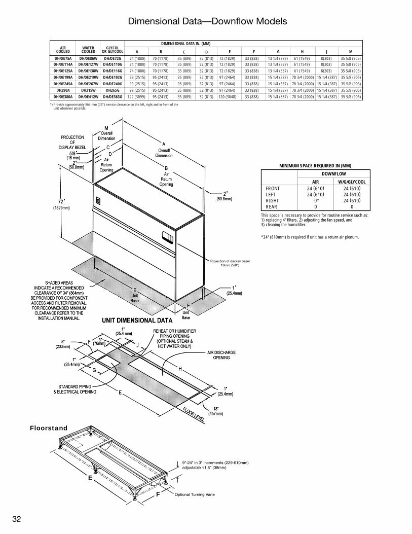
Floorstand
E
F
9"-24" in 3" increments (229-610mm)adjustable +1.5" (38mm)-
Optional Turning Vane
Dimensional Data—Downflow Models
32
MINIMUM SPACE REQUIRED IN (MM)
DOWNFLOW
AIR W/G/GLYCOOLFRONT 24 (610) 24 (610)LEFT 24 (610) 24 (610)RIGHT 0* 24 (610)REAR 0 0
This space is necessary to provide for routine service such as:1) replacing 4" filters, 2) adjusting the fan speed, and3) cleaning the humidifier.
*24" (610mm) is required if unit has a return air plenum.
Projection of display bezel16mm (5/8")
DIMENSIONAL DATA IN. (MM)AIR WATER GLYCOL
COOLED COOLED OR GLYCOOL
DH/DE75A DH/DE86W DH/DE72G 74 (1880) 70 (1178) 35 (889) 32 (813) 72 (1829) 33 (838) 13 1/4 (337) 61 (1549) 8(203) 35 5/8 (905)DH/DE114A DH/DE127W DH/DE110G 74 (1880) 70 (1178) 35 (889) 32 (813) 72 (1829) 33 (838) 13 1/4 (337) 61 (1549) 8(203) 35 5/8 (905)
DH/DE125A DH/DE138W DH/DE116G 74 (1880) 70 (1178) 35 (889) 32 (813) 72 (1829) 33 (838) 13 1/4 (337) 61 (1549) 8(203) 35 5/8 (905)
DH/DE199A DH/DE219W DH/DE192G 99 (2515) 95 (2413) 35 (889) 32 (813) 97 (2464) 33 (838) 15 1/4 (387) 78 3/4 (2000) 15 1/4 (387) 35 5/8 (905)
DH/DE245A DH/DE267W DH/DE240G 99 (2515) 95 (2413) 35 (889) 32 (813) 97 (2464) 33 (838) 15 1/4 (387) 78 3/4 (2000) 15 1/4 (387) 35 5/8 (905)
DH290A DH315W DH265G 99 (2515) 95 (2413) 35 (889) 32 (813) 97 (2464) 33 (838) 15 1/4 (387) 78 3/4 (2000) 15 1/4 (387) 35 5/8 (905)
DH/DE380A DH/DE412W DH/DE363G 122 (3099) 95 (2413) 35 (889) 32 (813) 120 (3048) 33 (838) 15 1/4 (387) 78 3/4 (2000) 15 1/4 (387) 35 5/8 (905)
1) Provide approximately 864 mm (34″) service clearance on the left, right and in front of theunit whenever possible.
A B C D E F G H J M

Maximum Electrical Load Amperage
Electrical Specifications—Downflow Models
Table 5—Air, Water, Glycol Cooled DH Models; 3 phase, 60 cycleReheat Options Electric None, Steam or Hot Water Electric None, Steam or Hot Water
Humidifier Options Infra-Red or Steam Generating* Infra-Red or Steam Generating* Steam or None Steam or None
Models/Motor HP Volts 208 230 460 575 208 230 460 575 208 230 460 575 208 230 460 575
DH 75A FLA 58.4 52.0 27.9 24.9 55.8 51.0 26.3 23.9 44.4 42.4 20.8 15.9 29.2 28.8 13.4 10.4
1.0 hp 86W WSA 73.0 65.0 34.9 31.1 59.0 54.2 27.7 25.0 54.5 52.1 25.5 19.5 32.4 32.0 14.9 11.5
72G MFCB 80 60 35 35 70 60 30 25 60 50 25 20 40 40 20 15
DH 75A FLA 60.1 53.6 28.7 25.6 57.5 52.6 27.1 24.6 46.1 44.0 21.6 16.6 30.9 30.4 14.2 11.1
1.5 hp 86W WSA 75.1 67.0 35.9 32.0 60.7 55.7 28.5 25.7 56.2 53.7 26.4 20.2 34.0 33.5 15.7 12.2
72G MFCB 80 60 40 35 70 60 30 30 60 50 25 20 45 45 20 15
DH 114A FLA 73.9 66.6 35.7 30.7 71.5 66.6 35.7 29.4 66.9 63.9 32.4 24.1 44.9 44.4 22.8 15.9
1.5 hp 127W WSA 92.4 83.1 44.0 38.4 76.4 71.5 38.2 31.1 82.2 78.6 39.9 29.6 49.8 49.3 25.3 17.6
110G MFCB 90 90 45 40 90 90 45 35 90 80 45 30 60 60 35 20
DH 114A FLA 75.7 68.2 36.5 31.3 73.3 68.2 36.5 30.0 68.7 65.5 33.2 24.7 46.7 46.0 23.6 16.5
2.0 hp 127W WSA 94.6 85.1 45.0 39.1 78.2 73.1 39.0 31.7 84.0 80.2 40.7 30.2 51.6 50.9 26.1 18.2
110G MFCB 90 90 45 40 90 90 45 35 90 90 45 30 70 70 35 25
DH 125A FLA 75.7 68.2 36.5 31.3 73.3 68.2 36.5 30.0 68.7 65.5 33.2 24.7 46.7 46.0 23.6 16.5
2.0 hp 138W WSA 94.6 85.1 45.0 39.1 78.2 73.1 39.0 31.7 84.0 80.2 40.7 30.2 51.6 50.9 26.1 18.2
116G MFCB 90 90 45 40 90 90 45 35 90 90 45 30 70 70 35 25
DH 125A FLA 78.8 71.0 37.9 32.5 76.4 71.0 37.9 31.2 71.8 68.3 34.6 25.9 49.8 48.8 25.0 17.7
3.0 hp 138W WSA 98.5 88.6 46.7 40.6 81.3 75.9 40.4 32.9 87.1 83.0 42.1 31.4 54.7 53.7 27.5 19.4
116G MFCB 100 90 50 45 100 90 50 35 90 90 45 30 70 70 35 25
DH 199A FLA 108.2 103.3 51.6 42.5 93.6 88.2 45.9 40.0 108.2 103.3 51.6 40.3 67.0 66.0 33.0 26.5
3.0 hp 219W WSA 133.2 126.7 63.3 53.1 100.7 95.2 49.4 42.8 132.6 126.7 63.3 49.4 74.1 73.1 36.5 29.3
192G MFCB 125 125 60 50 125 110 60 50 125 125 60 50 100 100 50 40
DH 199A FLA 114.3 108.9 54.4 44.7 99.7 93.8 48.7 42.2 114.3 108.9 54.4 42.5 73.1 71.6 35.8 28.7
5.0 hp 219W WSA 140.9 132.3 66.5 55.9 106.7 100.9 52.2 45.0 138.7 132.3 66.1 51.6 80.2 78.7 39.3 31.5
192G MFCB 125 125 70 50 125 125 60 50 125 125 70 50 100 100 50 40
DH 245A FLA 131.8 129.8 64.5 50.4 115.3 109.4 54.8 46.1 131.8 129.8 64.5 50.4 88.7 87.2 43.2 34.5
5.0 hp 267W WSA 160.6 158.4 78.7 61.5 124.3 118.4 59.2 49.7 160.6 158.4 78.7 61.5 97.7 96.2 47.6 38.0
240G MFCB 175 150 80 60 150 150 70 60 175 150 80 60 125 125 60 50
DH 245A FLA 139.3 136.6 67.9 53.3 122.8 116.2 58.2 49.0 139.3 136.6 67.9 53.3 96.2 94.0 46.6 37.4
7.5 hp 267W WSA 168.1 165.2 82.1 64.4 131.8 125.2 62.6 52.5 168.1 165.2 82.1 64.4 105.2 103.0 51.0 41.0
240G MFCB 175 175 90 70 150 150 80 60 175 175 90 70 125 125 60 50
DH 290A FLA 144.3 141.6 70.0 55.1 132.8 126.2 62.4 52.6 144.3 141.6 70.0 55.1 106.2 104.0 50.8 41.0
7.5 hp 315W WSA 174.3 171.5 84.7 66.6 143.1 136.4 67.4 56.6 174.3 171.5 84.7 66.6 116.4 114.2 55.8 45.0
265G MFCB 175 175 90 70 175 175 80 70 175 175 90 70 150 150 70 60
DH 380A FLA 171.6 164.4 78.7 63.6 171.6 164.4 76.8 63.6 167.0 163.7 78.7 61.6 145.0 142.2 65.2 52.0
10.0 hp 412W WSA 201.0 197.6 94.9 74.2 185.9 178.7 83.2 68.7 201.0 197.6 94.9 74.2 159.3 156.5 71.6 57.1
363G MFCB 225 225 110 80 225 225 100 80 225 225 110 80 200 200 90 70
NOTES—TABLE 51) FLA = FULL LOAD AMPS
WSA = WIRE SIZING AMPS(Minimum supply circuit ampacity)MFCB = Maximum Fuse or Circuit Breaker Size
2) Amperage requirements are based on the rated max F.L.A.current of each component in the unit. The rated max F.L.A.current of the unit is not the sum total of all components,but is the total of the components which operate duringmaximum electrical load conditions.
3) The values in the chart are for power of theDH unit only. The only electrical connection between theoutside heat rejection equipment and the DH unit is lowvoltage control wires. An electrical source is required forthe air cooled condenser (Table 11) or glycol pump and drycooler (Table 13, 14).
4) For water cooled models with hot gas reheat, the abovecolumns include amp values for one stage of electric reheat.
*When using steam generating humidifier on 6, 8, & 10 tonunits, the electrical data is lower. Please consult Liebert forvalues.
**Units with Steam or Hot Water Reheat require optional fanmotor (larger). Not available on 290A, 315W, 265G. OptionalCFM ratings do not apply for units with steam or hot waterreheat.
Standard unit with .5" external static pressure and standard cfm
33

NOTES—TABLE 71) FLA = FULL LOAD AMPS
WSA = WIRE SIZING AMPS(Minimum supply circuit ampacity)MFCB = Maximum Fuse or Circuit Breaker Size
2) Amperage requirements are based on the ratedmax F.L.A. current of each component in the unit.The rated max F.L.A. current of the unit is not thesum total of all components, but is the total of thecomponents which operate during maximumelectrical load conditions.
3) The values in the chart are for power of the DH unitonly. The only electrical connection between theoutside heat rejection equipment and the DH unit islow voltage control wires. An electrical source isrequired for the air cooled condenser (Table 11) orglycol pump and dry cooler (Table 13, 14).
4) Optional CFM ratings do not apply for units withsteam or hot water reheat.
*When using steam generating humidifier on 6, 8, &10 ton units, the electrical data is lower. Pleaseconsult Liebert for values.
Table 6—Water Cooled DH Models with Hot Gas ReheatReheat Options Hot Gas/1 Electric Hot Gas/1 Electric
Humidifier Options Infra–Red or Steam Generating* Steam or NoneModels/Motor HP Volts 208 230 460 575 208 230 460 575DH 86W FLA 55.8 51.0 26.3 23.9 32.6 31.3 15.2 11.71.0 hp WSA 59.0 54.2 27.9 25.9 39.8 38.2 18.6 14.3
MFCB 70 60 30 25 45 45 20 15DH 86W FLA 57.5 52.6 27.1 24.6 34.3 32.9 16.0 12.41.5 hp WSA 60.7 55.8 28.9 26.8 41.5 39.8 19.4 15.0
MFCB 70 60 30 30 50 45 20 15DH 127W FLA 71.5 66.6 35.7 29.4 49.4 47.4 24.1 17.71.5 hp WSA 76.4 71.5 38.2 31.1 60.3 58.0 29.5 21.6
MFCB 90 90 45 35 70 70 35 25DH 127W FLA 73.3 68.2 36.5 30.0 51.2 49.0 24.9 18.32.0 hp WSA 78.2 73.1 39.0 31.7 62.1 59.6 30.3 22.2
MFCB 90 90 45 35 70 70 35 25DH 138W FLA 73.3 68.2 36.5 30.0 51.2 49.0 24.9 18.32.0 hp WSA 78.2 73.1 39.0 31.7 62.1 59.6 30.3 22.2
MFCB 90 90 45 35 70 70 35 25DH 138W FLA 76.4 71.0 37.9 31.2 54.3 51.8 26.3 19.53.0 hp WSA 81.3 75.9 40.4 32.9 65.2 62.4 31.7 23.4
MFCB 100 90 50 35 70 70 35 25DH 219W FLA 93.6 88.2 45.9 40.0 78.9 75.6 37.8 29.73.0 hp WSA 100.7 95.2 49.4 42.8 96.0 92.1 46.1 36.2
MFCB 125 110 60 50 110 110 50 40DH 219W FLA 99.7 93.8 48.7 42.2 85.0 81.2 40.6 31.95.0 hp WSA 106.8 100.9 52.2 45.0 102.1 97.7 48.9 38.4
MFCB 125 125 60 50 110 110 50 45DH 267W FLA 115.3 109.4 54.8 46.1 98.4 96.6 48.0 37.75.0 hp WSA 124.3 118.4 59.3 49.7 118.8 117.0 58.1 45.6
MFCB 150 150 70 60 125 125 70 50DH 267W FLA 122.8 116.2 58.2 49.0 105.9 103.4 51.4 40.67.5 hp WSA 131.8 125.2 62.7 52.6 126.3 123.8 61.5 48.5
MFCB 150 150 80 60 150 125 70 50DH 315W FLA 132.8 126.2 62.4 52.6 110.9 108.4 53.5 42.47.5 hp WSA 143.1 136.4 67.4 56.6 132.6 130.0 64.1 50.8
MFCB 175 175 80 70 150 150 70 60
Table 7—Glycol Cooled DH Models with Hot Gas ReheatReheat Options Hot Gas Hot Gas
Humidifier Options Infra-Red or Steam Generating* Steam or NoneModels/Motor HP Volts 208 230 460 575 208 230 460 575DH 72G FLA 55.8 51.0 26.3 23.9 29.2 28.8 13.4 10.41.0 hp WSA 59.0 54.2 27.8 25.0 32.4 32.0 14.9 11.5
MFCB 70 60 30 25 40 40 20 15DH 72G FLA 57.5 52.6 27.1 24.6 30.9 30.4 14.2 11.11.5 hp WSA 60.7 55.8 28.6 25.7 34.1 33.6 15.7 12.2
MFCB 70 60 30 30 45 45 20 15DH 110G FLA 71.5 66.6 35.7 29.4 44.9 44.4 22.8 15.91.5 hp WSA 76.4 71.5 38.2 31.1 49.8 49.3 25.3 17.6
MFCB 90 90 45 35 60 60 35 20DH 110G FLA 73.3 68.2 36.5 30.0 46.7 46.0 23.6 16.52.0 hp WSA 78.2 73.1 39.0 31.7 51.6 50.9 26.1 18.2
MFCB 90 90 45 35 70 70 35 25DH 116G FLA 73.3 68.2 36.5 30.0 46.7 46.0 23.6 16.52.0 hp WSA 78.2 73.1 39.0 31.7 51.6 50.9 26.1 18.2
MFCB 90 90 45 35 70 70 35 25DH 116G FLA 76.4 71.0 37.9 31.2 49.8 48.8 25.0 17.73.0 hp WSA 81.3 75.9 40.4 32.9 54.7 53.7 27.5 19.4
MFCB 100 90 50 35 70 70 35 25DH 192G FLA 93.6 88.2 45.9 40.0 67.0 66.0 33.0 26.53.0 hp WSA 100.7 95.3 49.4 42.8 74.1 73.1 36.5 29.3
MFCB 125 110 60 50 100 100 50 40DH 192G FLA 99.7 93.8 48.7 42.2 73.1 71.6 35.8 28.75.0 hp WSA 106.8 100.9 52.2 45.0 80.2 78.7 39.3 31.5
MFCB 125 125 60 50 100 100 50 40DH 240G FLA 115.3 109.4 54.8 46.1 88.7 87.2 43.2 34.55.0 hp WSA 124.3 118.4 59.3 49.7 97.7 96.2 47.7 38.1
MFCB 150 150 70 60 125 125 60 50DH 240G FLA 122.8 116.2 58.2 49.0 96.2 94.0 46.6 37.47.5 hp WSA 131.8 125.2 62.7 52.6 105.2 103.0 51.1 41.0
MFCB 150 150 80 60 125 125 60 50DH 265G FLA 132.8 126.2 62.4 52.6 106.2 104.0 50.8 41.07.5 hp WSA 143.1 136.5 67.4 56.6 116.5 114.3 55.8 45.0
MFCB 175 175 80 70 150 150 70 60
NOTES—TABLE 61) FLA = FULL LOAD AMPS
WSA = WIRE SIZING AMPS(Minimum supply circuit ampacity)MFCB = Maximum Fuse or Circuit Breaker Size
2) Amperage requirements are based on the rated max F.L.A.current of each component in the unit. The rated max F.L.A.current of the unit is not the sum total of all components,but is the total of the components which operate duringmaximum electrical load conditions.
3) The values in the chart are for power of theDH unit only. The only electrical connection between theoutside heat rejection equipment and the DH unit is lowvoltage control wires. An electrical source is required forthe air cooled condenser (Table 11) or glycol pump and drycooler (Table 13, 14).
4) For water cooled models with hot gas reheat, the abovecolumns include amp values for one stage of electric reheat.
* When using steam generating humidifier on 6, 8, & 10 tonunits, the electrical data is lower. Please consult Liebert forvalues.
**Units with Steam or Hot Water Reheat require optional fanmotor (larger). Not available on 290A, 315W, 265G. OptionalCFM ratings do not apply for units with steam or hot waterreheat.
Standard unit with .5" external static pressure and standard cfm
34

Electrical Specifications—Downflow Models
Table 8—Glycool or Dual Cooling DE ModelsReheat Options Electric None Electric None
Humidifier Options Infra-Red or Steam Generating* Infra-Red or Steam Generating* None NoneModels/Motor HP Volts 208 230 460 575 208 230 460 575 208 230 460 575 208 230 460 575DE 72G FLA 60.1 53.6 28.7 25.6 57.5 52.6 27.1 24.6 46.1 44.0 21.6 16.6 30.9 30.4 14.2 11.11.5 hp 75A WSA 75.1 67.0 35.9 32.0 60.7 55.8 28.6 25.7 56.2 53.7 26.4 20.2 34.1 33.6 15.7 12.2
86W MFCB 80 60 40 35 70 60 30 30 60 50 25 20 45 45 20 15DE 110G FLA 75.7 68.2 36.5 31.3 73.3 68.2 36.5 30.0 68.7 65.5 33.2 24.7 46.7 46.0 23.6 16.52.0 hp 114A WSA 94.6 85.1 45.0 39.1 78.2 73.1 39.0 31.7 84.0 80.2 40.7 30.2 51.6 50.9 26.1 18.2
127W MFCB 90 90 45 40 90 90 45 35 90 90 45 30 70 70 35 25DE 116G FLA 78.8 71.0 37.9 32.5 76.4 71.0 37.9 31.2 71.8 68.3 34.6 25.9 49.8 48.8 25.0 17.73.0 hp 125A WSA 98.5 88.6 46.8 40.6 81.3 75.9 40.4 32.9 87.1 83.0 42.1 31.4 54.7 53.7 27.5 19.4
138W MFCB 100 90 50 45 100 90 50 35 90 90 45 30 70 70 35 25DE 192G FLA 114.3 108.9 54.4 44.7 99.7 93.8 48.7 42.2 114.3 108.9 54.4 42.5 73.1 71.6 35.8 28.75.0 hp 199A WSA 140.9 132.3 66.5 55.9 106.8 100.9 52.2 45.0 138.7 132.3 66.1 51.6 80.2 78.7 39.3 31.5
219W MFCB 125 125 70 50 125 125 60 50 125 125 70 50 100 100 50 40DE 240G FLA 139.3 136.6 67.9 53.3 122.8 116.2 58.2 49.0 139.3 136.6 67.9 53.3 96.2 94.0 46.6 37.47.5 hp 245A WSA 168.1 165.3 82.1 64.4 131.8 125.2 62.7 52.6 168.1 165.3 82.1 64.4 105.2 103.0 51.0 41.0
267W MFCB 175 175 90 70 150 150 80 60 175 175 90 70 125 125 60 50DE 363G FLA 171.6 164.4 78.7 63.6 171.6 164.4 76.8 63.6 167.0 163.7 78.7 61.6 145.0 142.2 65.2 52.010.0 hp 380A WSA 201.1 197.6 94.9 74.3 185.9 178.7 83.2 68.7 201.1 197.6 94.9 74.2 159.3 156.5 71.6 57.1
412W MFCB 225 225 110 80 225 225 100 80 225 225 110 80 200 200 90 70
Table 10—Indoor Evaporator Fan Motor Electrical Requirements208 230 460 575
FLA LRA FLA LRA FLA LRA FLA LRA1.0 HP 4.0 24.8 3.6 21.6 1.8 10.8 1.4 8.41.5 HP 5.7 35.9 5.2 31.2 2.6 15.6 2.1 12.62.0 HP 7.5 46.9 6.8 40.8 3.4 20.4 2.7 16.23.0 HP 10.6 66.0 9.6 58.0 4.8 26.8 3.9 23.45.0 HP 16.7 105.0 15.2 91.0 7.6 45.6 6.1 36.67.5 HP 24.2 152.0 22.0 132.0 11.0 66.0 9.0 54.0
10.0 HP 30.8 193.0 28.0 168.0 14.0 84.0 11.0 66.0
1) Refer to General Data Section for standard fan motor size on units.
Table 9—Electrical Requirements Per CompressorUnit 208V 230V 460V 575V
Model 0A RLA LRA 0A RLA LRA 0A RLA LRA OA RLA LRA75A 10.2 12.6 82.0 9.2 12.6 82.0 4.6 5.8 41.0 3.7 4.5 28.4
114A 16.6 19.6 141.0 15.0 19.6 141.0 7.5 10.1 62.5 6.0 6.9 40.0125A 18.4 19.6 141.0 16.6 19.6 141.0 7.8 10.1 62.5 6.2 6.9 40.0199A 23.7 28.2 160.0 21.4 28.2 160.0 10.7 14.1 80.0 8.6 11.3 64.0245A 28.7 36.0 198.0 26.0 36.0 198.0 13.0 17.8 99.0 10.4 14.2 79.0290A 34.6 41.0 228.0 30.8 41.0 228.0 15.4 19.9 114.0 12.3 16.0 91.0380A 49.2 57.1 266.0 44.5 57.1 266.0 22.3 25.6 120.0 17.8 20.5 96.086W 8.6 12.6 82.0 7.8 12.6 82.0 3.9 5.8 41.0 3.1 4.5 28.4
127W 13.9 19.6 141.0 12.6 19.6 141.0 6.3 10.1 62.5 5.0 6.9 40.0138W 14.2 19.6 141.0 12.8 19.6 141.0 6.4 10.1 62.5 5.1 6.9 40.0219W 19.9 28.2 160.0 18.0 28.2 160.0 9.0 14.1 80.0 7.2 11.3 64.0267W 25.2 36.0 198.0 22.8 36.0 198.0 11.4 17.8 99.0 9.1 14.2 79.0315W 30.1 41.0 228.0 27.2 41.0 228.0 13.6 19.9 114.0 10.9 16.0 91.0412W 43.2 57.1 266.0 39.1 57.1 266.0 19.6 25.6 120.0 15.6 20.5 96.0
72G 11.3 12.6 82.0 10.2 12.6 82.0 5.1 5.8 41.0 4.1 4.5 28.4110G 17.7 19.6 141.0 16.0 19.6 141.0 8.0 10.1 62.5 6.4 6.9 40.0116G 18.8 19.6 141.0 17.0 19.6 141.0 8.5 10.1 62.5 6.8 6.9 40.0192G 24.8 28.2 160.0 22.4 28.2 160.0 11.2 14.1 80.0 9.0 11.3 64.0240G 31.0 36.0 198.0 28.0 36.0 198.0 14.0 17.8 99.0 11.2 14.2 79.0265G 36.7 41.0 228.0 33.2 41.0 228.0 16.6 19.9 114.0 13.3 16.0 91.0363G 53.5 57.1 266.0 48.6 57.1 266.0 24.3 25.6 120.0 19.4 20.5 96.0
NOTES—TABLE 9OA — Operating Amps. This value is the
actual operating amperage drawduring normal operator of the unitfor capacities as shown in GENERALDATA SECTION.
LRA— Locked Rotor Amps.RLA— Rated Load Amps.
NOTES—TABLE 81) FLA = FULL LOAD AMPS
WSA = WIRE SIZING AMPS(Minimum supply circuit ampacity)MFCB = Maximum Fuse or Circuit Breaker Size
2) Amperage requirements are based on the rated max F.L.A. current of each component in the unit. The rated max F.L.A. current of the unit is not the sum total of all components, but is the total of thecomponents which operate during maximum electrical load conditions.
3) The values in the chart are for power of the DE unit only. The only electrical connection between the outside heat rejection equipment and the DE unit is low voltage control wires. An electrical source isrequired for the air cooled condenser (Table 11) or glycol pump and dry cooler (Table 13, 14).
4) Optional CFM. ratings do not apply for units with steam or hot water reheat.*When using steam generating humidifier on 6, 8, & 10 ton units, the electrical data is lower. Please consult Liebert for values.
35

DRYCOOLER/CONDENSER DATA
MODEL A IN. (MM) B IN. (MM)
1-Fan 51 7/16 (1308) 44 (1117.6)
2-Fan 91 7/16 (2324) 84 (2133.6)
3-Fan 131 7/16 (3340) 124 (3149.6)
4-Fan 171 1/2 (4356) 164 (4165.6)
Dimensional Data/Electrical Data—Drycoolers, Condensers,Pump Packages, Temperature/Humidity Recorder
Table 11—Air Cooled Condenser Amperage†FAN SPEED CONTROL (–20°F) LEE-TEMP (–30°F)
MODELS VOLTS PH FLA WSA OPD PH FLA WSA OPDDH/VH 75A 208/230 1 4.8 6.0 15 3 4.0 5.0 15
460* 1 2.4 3.0 15 3 2.0 2.5 15575* 1 1.9 2.4 15 3 1.4 1.75 15
DH/VH 114A 208/230 3 8.8 10.0 20 3 8.0 9.0 20460 3 4.4 5.0 15 3 4.0 4.5 15575 3 3.3 3.8 15 3 2.8 3.15 15
DH/VH 125A 208/230 3 8.8 10.0 20 3 8.0 9.0 20460 3 4.4 5.0 15 3 4.0 4.5 15575 3 3.3 3.8 15 3 2.8 3.15 15
DH/VH 199A 208/230 3 8.8 10.0 20 3 8.0 9.0 20460 3 4.4 5.0 15 3 4.0 4.5 15575 3 3.3 3.8 15 3 2.8 3.15 15
DH/VH 245A 208/230 3 12.8 14.0 25 3 12.0 13.0 20460 3 6.4 7.0 15 3 6.0 6.5 15575 3 4.7 5.2 15 3 4.2 4.55 15
DH/VH 290A 208/230 3 12.8 14.0 25 3 12.0 13.0 20460 3 6.4 7.0 15 3 6.0 6.5 15575 3 4.7 5.2 15 3 4.2 4.55 15
DH/VH 380A 208/230 3 16.8 18.0 30 3 16.0 17.0 25460 3 8.4 9.0 15 3 8.0 8.5 15575 3 6.1 6.6 15 3 5.6 5.95 15
NOTES: TABLE 111) 95°F Ambient Condensers2) FLA=Full Load Amps. WSA=Wire Sizing Amps (Minimum supply circuit ampacity) MFCB=Maximum Fuse on Circuit Breaker Size
†Data shown applies to the standard factory supplied condensers. These may vary in local areas and verification with the Liebertrepresentative is strongly recommended.*Condenser equipped with stepdown transformer and 208/230 Motor.
Table 12—Lee-Temp ReceiverHeater Pads
ALL AIR COOLED MODELSVOLTS 120 230WATTS/PAD 150 150TOTAL AMPS(2 PADS) 2.5A 1.3AWSA (2 PADS) 3.1 1.6OPD (2 PADS) 15 15
NOTES: TABLE 121) Separate electrical source required for
continuous operation of single phasesilicone rubber heater pads for Lee-Temp.
2) Two pads are required for standardinstallations (one per circuit.)
1097mm(43 3/16˝)
Dimension includes electric box on end of receiver
Lee-TempReceiver(when specified)
B
A
1095mm(37 7/8˝)
1105mm(43 9/16˝)
Drycoolerand Air CooledCondenser
Temperature and humidity sensorswith vented cap mounted byLiebert at this location.Ten (10) feet (3048mm) ofcable supplied foroptional mounting by others.
Temperature and humidity sensorswith vented cap. 5.8˝
(147mm)
14.0˝(356mm)
14.0˝(356mm)
Temperature/Humidity Recorder
483mm(19˝)
NOTE:1. Single Pump Packages are 171/4˝ (438.2mm) wide.
Dual Pump Packages are 321/4˝ (819.2mm) wide.
Provided onDual PumpPackage Only
See Note 1 768.4mm (301/4˝)
Glycol Pump Package
36
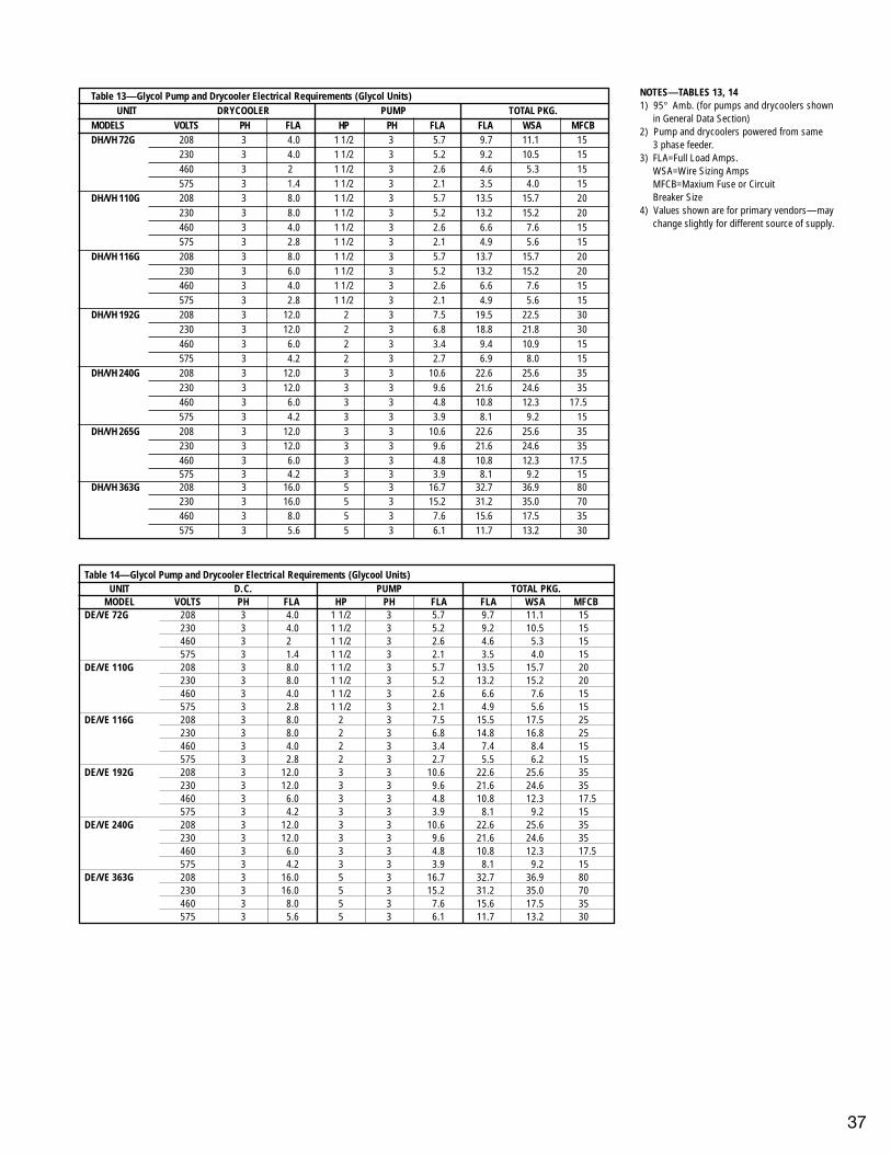
Table 13—Glycol Pump and Drycooler Electrical Requirements (Glycol Units)UNIT DRYCOOLER PUMP TOTAL PKG.
MODELS VOLTS PH FLA HP PH FLA FLA WSA MFCBDH/VH 72G 208 3 4.0 1 1/2 3 5.7 9.7 11.1 15
230 3 4.0 1 1/2 3 5.2 9.2 10.5 15460 3 2 1 1/2 3 2.6 4.6 5.3 15575 3 1.4 1 1/2 3 2.1 3.5 4.0 15
DH/VH 110G 208 3 8.0 1 1/2 3 5.7 13.5 15.7 20230 3 8.0 1 1/2 3 5.2 13.2 15.2 20460 3 4.0 1 1/2 3 2.6 6.6 7.6 15575 3 2.8 1 1/2 3 2.1 4.9 5.6 15
DH/VH 116G 208 3 8.0 1 1/2 3 5.7 13.7 15.7 20230 3 6.0 1 1/2 3 5.2 13.2 15.2 20460 3 4.0 1 1/2 3 2.6 6.6 7.6 15575 3 2.8 1 1/2 3 2.1 4.9 5.6 15
DH/VH 192G 208 3 12.0 2 3 7.5 19.5 22.5 30230 3 12.0 2 3 6.8 18.8 21.8 30460 3 6.0 2 3 3.4 9.4 10.9 15575 3 4.2 2 3 2.7 6.9 8.0 15
DH/VH 240G 208 3 12.0 3 3 10.6 22.6 25.6 35230 3 12.0 3 3 9.6 21.6 24.6 35460 3 6.0 3 3 4.8 10.8 12.3 17.5575 3 4.2 3 3 3.9 8.1 9.2 15
DH/VH 265G 208 3 12.0 3 3 10.6 22.6 25.6 35230 3 12.0 3 3 9.6 21.6 24.6 35460 3 6.0 3 3 4.8 10.8 12.3 17.5575 3 4.2 3 3 3.9 8.1 9.2 15
DH/VH 363G 208 3 16.0 5 3 16.7 32.7 36.9 80230 3 16.0 5 3 15.2 31.2 35.0 70460 3 8.0 5 3 7.6 15.6 17.5 35575 3 5.6 5 3 6.1 11.7 13.2 30
NOTES—TABLES 13, 141) 95° Amb. (for pumps and drycoolers shown
in General Data Section)2) Pump and drycoolers powered from same
3 phase feeder.3) FLA=Full Load Amps.
WSA=Wire Sizing AmpsMFCB=Maxium Fuse or CircuitBreaker Size
4) Values shown are for primary vendors—maychange slightly for different source of supply.
Table 14—Glycol Pump and Drycooler Electrical Requirements (Glycool Units)UNIT D.C. PUMP TOTAL PKG.
MODEL VOLTS PH FLA HP PH FLA FLA WSA MFCBDE/VE 72G 208 3 4.0 1 1/2 3 5.7 9.7 11.1 15
230 3 4.0 1 1/2 3 5.2 9.2 10.5 15460 3 2 1 1/2 3 2.6 4.6 5.3 15575 3 1.4 1 1/2 3 2.1 3.5 4.0 15
DE/VE 110G 208 3 8.0 1 1/2 3 5.7 13.5 15.7 20230 3 8.0 1 1/2 3 5.2 13.2 15.2 20460 3 4.0 1 1/2 3 2.6 6.6 7.6 15575 3 2.8 1 1/2 3 2.1 4.9 5.6 15
DE/VE 116G 208 3 8.0 2 3 7.5 15.5 17.5 25230 3 8.0 2 3 6.8 14.8 16.8 25460 3 4.0 2 3 3.4 7.4 8.4 15575 3 2.8 2 3 2.7 5.5 6.2 15
DE/VE 192G 208 3 12.0 3 3 10.6 22.6 25.6 35230 3 12.0 3 3 9.6 21.6 24.6 35460 3 6.0 3 3 4.8 10.8 12.3 17.5575 3 4.2 3 3 3.9 8.1 9.2 15
DE/VE 240G 208 3 12.0 3 3 10.6 22.6 25.6 35230 3 12.0 3 3 9.6 21.6 24.6 35460 3 6.0 3 3 4.8 10.8 12.3 17.5575 3 4.2 3 3 3.9 8.1 9.2 15
DE/VE 363G 208 3 16.0 5 3 16.7 32.7 36.9 80230 3 16.0 5 3 15.2 31.2 35.0 70460 3 8.0 5 3 7.6 15.6 17.5 35575 3 5.6 5 3 6.1 11.7 13.2 30
37

Guide Specifications
1.0 GENERAL
1.1 SummaryThese specifications describerequirements for a precisionenvironmental control system.The system shall be designedto maintain temperature andhumidity conditions in therooms containing electronicequipment.
The manufacturer shall designand furnish all equipment tobe fully compatible with heatdissipation requirements ofthe room.
1.2 DesignRequirementsThe precision environmentalcontrol system shall be aLiebert self-contained factoryassembled unit with (upflow)(down-flow) air delivery. Thesystem shall have a totalcooling capacity of____ BTU/HR, (kW) with a sensiblecooling capacity of ____ BTU/HR (kW) based on an enteringair temperature of ____ °F (°C)dry bulb and ____ °F (°C) wetbulb. The unit is to be sup-plied with ____ volt ____ ph____ Hz electrical service.
1.3 SubmittalsSubmittals shall be providedwith the proposal and shallinclude: Single-Line Diagrams;Dimensional, Electrical, andCapacity Data; Piping andElectrical ConnectionDrawings.
2.0 PRODUCT
2.1 Cabinet and FrameConstructionThe frame shall be construc-ted of mig welded tubularsteel. It shall be painted usingthe autophoretic coatingprocess for maximum cor-rosion protection. The exteriorpanels shall be insulated witha minimum 1 in. (25.4mm),1.5 lbs. (.68 kg) density fiberinsulation. The main frontpanel shall have captive 1/4turn fasteners. The main unitcolor shall be ______. Theaccent color shall be ______.The exterior panels shall bepowder coated.
2.1.1 (Optional) HeavyGauge Panels on UpflowUnitsThe exterior panels shall be 16gauge steel for operation withhigh external static pressures.
2.2 Filter Chamber(Downflow units)The filter chamber shall be anintegral part of the system,located within the cabinetserviceable from the end ofthe unit or the top of the unit(if there is no plenum). Thefilters shall be rated not lessthan ____% efficiency (basedon ASHRAE 52.1).
2.2 Filter Chamber(Upflow units w/front &bottom return)The filter chamber shall be anintegral part of the system,located within the cabinet,serviceable from the end of theunit. The filters shall be ratednot less than ____% efficiency(based on ASHRAE 52.1).
2.2 Filter Chamber(Upflow units w/rearreturn)The filter units chamber shall belocated on the back of thecabinet, serviceable from theend of the unit. The filters shallbe rated not less than ____%efficiency (based on ASHRAE52.1).
2.3 Fan SectionThe fan section shall bedesigned for ___ CFM (m3h)at an external static pressureof ___ in. wg. (Pa).The fansshall be the centrifugal type,double width double inlet, andshall be statically and dynami-cally balanced as a completedassembly to a maximumvibration level of two mils inany plane. The shaft shall beheavy duty steel with self-aligning ball bearings with aminimum life span of 100,000hours. The fan motor shall be____ hp (kW) at 1750 RPMand mounted on an adjustableslide base. The drive packageshall be multi-belt, variablespeed, sized for 200% ofthe fan motor horsepower.The fans shall be located todraw air over the A-Framecoil to ensure even airdistribution and maximumcoil performance.
2.4 Infrared HumidifierThe humidifier shall be of theinfrared type consisting ofhigh intensity quartz lampsmounted above and out of thewater supply. The evaporatorpan shall be stainless steeland arranged to be service-able without disconnectinghigh voltage electrical connec-tions. The complete humidifiersection shall be pre-pipedready for final connection. Theinfrared humidification systemshall use bypass air to preventover-humidification of thecomputer room. The humidi-fier shall have a capacity of____ lbs./hr. (kg/h). The humid-ifier shall be equipped withan automatic water supplysystem. The system has anadjustable water-overfeed toprevent mineral precipitation.
2.4 Steam GeneratingHumidifierThe environmental controlsystem shall be equipped witha steam generating humidifierthat is controlled by the micro-processor control system.It shall be complete with dis-posable canister, all supplyand drain valves, steam distri-butor, and electronic controls.
The need to change canistershall be annunciated on themicroprocessor controlpanel. The humidifier shallbe designed to operate withwater conductivity from200–500 micromhos.
2.4 Steam GridHumidifierThe steam humidifier shallbe the “Armstrong” steamseparator type with an internaldrying chamber and steamjacketed stainless steel distri-bution manifold. Completesystem shall include a pre-piped solenoid control valve,inverted bucket steam trap,and cleanable Y-strainer. Allmechanical control compo-nents shall be located in aseparate compartment, iso-lated from the air stream.The humidifier shall have acapacity of ____ lbs./hr. (kg/h)at ____ PSIG (kPa) steamsupply pressure.
2.5 Electric ReheatThe electric reheat coils shallbe low watt density, 304/304stainless steel fin tubularconstruction, protected bythermal safety switches, shallbe ____ BTU/HR, ____ kW,controlled in three stages.
2.5 Steam ReheatThe steam reheat coil shallhave copper tubes and alum-inum fins with a capacity of____ BTU/HR (kW) with ____PSIG (kPa) steam. The systemshall be factory pre-piped witha 2-way modulating controlvalve, Y-strainer, and F & Tsteam trap.
2.5 Hot Water ReheatThe hot water reheat coil shallhave copper tubes and alum-inum fins with a capacity of____ BTU/HR (kW) when sup-plied with ____ °F (°C) enteringwater temperature at ____GPM (l/s) flow rate. Maximumpressure drop shall be ____PSI (kPa). The control systemshall be factory prepiped witha 2-way modulating controlvalve and cleanable Y-strainer.
38
2.6 AdvancedControl ProcessorThe Advancedcontrol processor shall bemicroprocessor based witha front monitor LCD displaypanel and control keys foruser inputs. The controlsshall be menu driven withon-screen prompts for easyuser operation. The systemshall allow user review andprogramming of temperatureand humidity setpoints, alarmparameters, and setup selec-tions including choice of con-trol type. A password shallbe required to make systemchanges. For all user selec-tions, the range of acceptableinput (temperature, humidity,or time delay) shall be dis-played on the monitor screen.The system shall providemonitoring of room condi-tions, operational status in %of each function, componentrun times, date and time, andfour analog inputs from sen-sors provided by others.
ControlThe control system shall allowprogramming of the followingroom conditions:• Temperature Setpoint
65–85°F (18–29°C)• Temperature Sensitivity
±1° to 9.9°F(0.6 to 5.6°C) in 0.1°F (.1°C)increments
• Humidity Setpoint20–80% R.H.
• Humidity Sensitivity+1% to +30% R.H.
All setpoints shall be adjust-able from the individual unitfront monitor panel. Temper-ature and Humidity Sensorsshall be capable of beingcalibrated using the frontmonitor panel controls tocoordinate with other tem-perature and humidity sen-sors in the room.
Predictive Humidity ControlThe microprocessor shallcalculate the moisture con-tent in the room and preventunnecessary humidificationand dehumidification cyclesby responding to changes indewpoint temperature.
In addition, the system shallprovide the following internalcontrols:
Compressor Short-CycleControlThe control system shallinclude a program to preventcompressor short cycling.
Automatic CompressorSequencingThe microprocessor shallautomatically change thelead/lag sequence of thecompressors after each startto lengthen compressor-oncycles and even compressorwear.
System Auto-RestartFor start-up after power fail-ure, the system shall provideautomatic restart with a pro-grammable (up to 9.9 minutesin 6-second increments) timedelay. Programming can beperformed either at the unit orfrom the central site monitor-ing system.
Sequential Load ActivationDuring start-up, or afterpower failure, the micropro-cessor shall sequenceoperational load activationto minimize inrush current.Systems allowing multipleloads to start simultaneouslyare unacceptable.
Hot Water/Econ-o-coilFlush CyclesHot water coils and Econ-o-coils shall be automaticallyflushed to prevent the buildupof contaminants. Systemswithout this feature shallinclude the necessary devicesto bypass fluid into the coil ona programmed basis.
Front Monitor Display PanelThe microprocessor shallprovide a front monitor LCDbacklit display panel with4 rows of 20 characters withadjustable contrast. Thisdisplay (along with five frontmounted control keys) shall bethe only operator interfacerequired to obtain all availablesystem information such asroom conditions, operationalstatus, alarms, control andalarm setpoints, and all userselections including alarmdelays, sensor calibration,DIP switch selections, anddiagnostics. All indicatorsshall be in language form.No symbols or codes shallbe acceptable.
AlarmsThe microprocessor shallactivate an audible and visualalarm in event of any of thefollowing conditions:
High TemperatureLow TemperatureHigh HumidityLow HumidityShort CycleCompressorOverload (#1 and #2) (opt)Main Fan Overload (opt)Humidifier ProblemHigh Head Pressure
(#1 and #2)Change FiltersLoss of Air FlowLow Suction PressureLoss of PowerCustom Alarm
(#1 to #4)Custom alarms are fourcustomer accessible alarminputs to be indicated on thefront panel. Custom alarmscan be identified with pre-pared (programmed) labelsfor the following frequentlyused inputs:
Water Under FloorSmoke DetectedStandby GC Pump OnLoss of Water FlowStandby Unit On
User customized text can beentered for two of the fourcustom alarms.
Each alarm (unit and custom)can be separately enabled ordisabled, selected to activatethe common alarm, andprogrammed for a time delayof 0 to 255 seconds.
39

Audible AlarmThe audible alarm shallannunciate any alarm that isenabled by the operator.
Common AlarmA programmable commonalarm shall be provided tointerface user selected alarmswith a remote alarm device.
Remote MonitoringAll alarms shall be commun-icated to the Liebert sitemonitoring system with thefollowing information: dateand time of occurrence, unitnumber, and present temper-ature and humidity.
Control TypeThe user shall be able toselect the type of control theadvanced microprocessor willuse. Selections available shallbe intelligent, proportional,and tunable PID (proportional,integral, and derivative gains).The intelligent control shallincorporate control logic thatuses artificial intelligencetechniques including “fuzzylogic” and “expert systems”methods to maintain precise,stable control. If tunable PIDis selected, the user shall beable to program each of thethree gains.
Analog InputsThe system shall include fourcustomer accessible analoginputs for sensors providedby others. The analog inputsshall accept a 4 to 20 mAsignal. The user shall be ableto change the input to 0 to5 vdc or 0 to 10 vdc if desired.The gains for each analoginput shall be programmablefrom the front panel. Theanalog inputs shall be able tobe monitored from the frontpanel.
DiagnosticsThe control system andelectronic circuitry shall beprovided with self-diagnosticsto aid in troubleshooting. Themicrocontroller board shall bediagnosed and reported aspass/not pass. Control inputsshall be indicated as on or off
Guide Specifications
at the front monitor panel.Control outputs shall be ableto be turned on or off from thefront monitor panel withoutusing jumpers or a serviceterminal.
Data CollectionThe control system shallmaintain accumulativeoperating hours of compres-sors, reheats, humdifier, fanmotor and Econ-o-coil. Theten most recent alarms shallalso be retained.
CommunicationsThe microprocessor shall becompatible with all Liebertremote monitoring and controldevices.
2.6 Advanced Micropro-cessor Control w/Graphics(Optional)The optional advancedcontrol processor shall bemicroprocessor based witha front monitor dot matrixdisplay panel and control keysfor user inputs. The controlsshall be menu driven with on-screen prompts for easy useroperation. The system shallallow user review and pro-gramming of temperatureand humidity setpoints, alarmparameters, and setup selec-tions including choice ofcontrol type. A password shallbe required to make systemchanges. For all user selec-tions, the range of acceptableinput (temperature, humidity,or time delay) shall be dis-played on the monitor screen.The system shall providemonitoring of room condi-tions, operational status in %of each function, componentrun times, date and time,and four analog inputs fromsensors provided by others.
ControlThe control system shall allowprogramming of the followingroom conditions:• Temperature Setpoint
65–85°F (18–29°C)• Temperature Sensitivity
+1° to + 9.9°F (°C) in 0.1°F(°C) increments
• Humidity Setpoint20–80% R.H.
• Humidity Sensitivity+1% to +30% R.H.
All setpoints shall be adjust-able from the individual unitfront monitor panel. Tempera-ture and Humidity Sensorsshall be capable of being cali-brated using the front monitorpanel controls to coordinatewith other temperature andhumidity sensors in the room.
Predictive Humidity ControlThe microprocessor shallcalculate the moisture con-tent in the room and preventunnecessary humidificationand dehumidification cyclesby responding to changesin dewpoint temperature. Inaddition, the system shallprovide the following internalcontrols:
Compressor Short-CycleControlThe control system shallprevent compressor short-cycling by a 3-minute timerfrom compressor stop tothe next start.
Automatic CompressorSequencingThe microprocessor shallautomatically change thelead/lag sequence of thecompressors after each startto lengthen compressor-oncycles and even compressorwear.
System Auto-RestartFor start-up after power fail-ure, the system shall provideautomatic restart with a pro-grammable (up to 9.9 minutesin 6-second increments) timedelay. Programming can beperformed either at the unit orfrom the central site monitor-ing system.
Sequential Load ActivationDuring start-up, or afterpower failure, the micropro-cessor shall sequenceoperational load activationto minimize inrush current.Systems allowing multipleloads to start simultaneouslyare unacceptable.
Hot Water/Econ-o-coilFlush CyclesHot water coils and Econ-o-coils shall be automaticallyflushed to prevent the buildupof contaminants. Systemswithout this feature shallinclude the necessary devicesto bypass fluid into the coil ona programmed basis.
Front Monitor Display PanelThe microprocessor shallprovide a front monitor 240 x128 dot matrix graphicsdisplay panel with backlight-ing. This display (along withfive front mounted controlkeys) shall be the only oper-ator interface required toobtain all available systeminformation such as roomconditions, operational status,graphical data, alarms, controland alarm set-points, and alluser selections includingalarm delays, sensor calibra-tion, DIP switch selections,and diagnostics. All indicatorsshall be in language form. Nosymbols or codes shall beacceptable.
AlarmsThe microprocessor shallactivate an audible and visualalarm in event of any of thefollowing conditions:
High TemperatureLow TemperatureHigh HumidityLow HumidityShort CycleCompressorOverload #1 and #2 (Opt)Main Fan Overload (Opt)Humidifier ProblemHigh Head Pressure
(#1 and #2)Change FiltersLoss of Air FlowLow Suction PressureLoss of PowerCustom Alarm
(#1 to #4)Custom alarms are fourcustomer accessible alarminputs to be indicated on thefront panel. Custom alarms
40

can be identified with pre-pared (programmed) labelsfor the following frequentlyused inputs:
Water Under FloorSmoke DetectedStandby GC Pump OnLoss of Water FlowStandby Unit On
User customized text can beentered for all four customalarms.
Each alarm (unit and custom)can be separately enabled ordisabled, selected to activatethe common alarm, and pro-grammed for a time delay of0 to 255 seconds.
Audible AlarmThe audible alarm shallannunciate any alarm thatis enabled by the operator.
Common AlarmA programmable commonalarm shall be provided tointerface user selected alarmswith a remote alarm device.
Remote MonitoringAll alarms shall be communi-cated to the Liebert sitemonitoring system with thefollowing information: dateand time of occurrence,unit number, and presenttemperature and humidity.
Control TypeThe user shall be able toselect the type of control theadvanced microprocessor willuse. Selections available shallbe intelligent, proportional,and tunable PID (proportional,integral, and derivative gains).The intelligent control shallincorporate control logic thatuses artificial intelligencetechniques including “fuzzylogic” and “expert systems”methods to maintain precise,stable control. If tunable PIDis selected, the user shall beable to program each of thethree gains.
Analog InputsThe system shall include fourcustomer accessible analoginputs for sensors provided byothers. The analog inputs shallaccept a 4 to 20 mA or 0 to 10vdc signal. The user shall beable to change the input to 0to 5 vdc if desired. The gainsfor each analog input shall beprogrammable from the frontpanel. The analog inputs shallbe able to be monitored fromthe front panel.
DiagnosticsThe control system and elec-tronic circuitry shall be pro-vided with self-diagnosticsto aid in troubleshooting. Themicrocontroller board shall bediagnosed and reported aspass/not pass. Control inputsshall be indicated as on or offat the front monitor panel.Control outputs shall be ableto be turned on or off from thefront monitor panel withoutusing jumpers or a serviceterminal.
Data CollectionThe control system shallmaintain accumulativeoperating hours of compres-sors, reheats, humdifier, fanmotor, Econ-o-coil, and heatrejection. The sixty mostrecent alarms shall alsobe retained.
GraphingThe control shall display thefollowing graphical data:• temperature, humidity, analog
inputs• component operating status
by hour• leak detection floor plan• operating status
CommunicationsThe microprocessor shall becompatible with all Liebertremote monitoring and controldevices.
2.7 CompressorizedSystems
2.7.1Dual RefrigerationSystemsEach refrigeration circuit shallinclude hot gas mufflers, liquidline filter dryers, refrigerantsight glass with moisture indi-cator adjustable, externallyequalized expansion values,and liquid line solenoid valves.
2.7.2Semi-HermeticCompressorsThe compressors shall belocated in a separate com-partment so they may beserviced during operation ofthe equipment. The compres-sor shall be semi-hermeticwith a suction gas cooledmotor, vibration isolators,thermal overloads, oil sightglass, manual reset highpressure switch, pump downlow pressure switch, suctionline strainer, reversible oilpumps for forced feed lubri-cation, a maximum operatingspeed of 1750 RPM, and aminimum EER of ____.
2.7.2 (Optional) Four-StepRefrigeration SystemThe environmental controlsystem shall include cylinderunloaders on the semi-hermetic compressors. Theunloaders shall be activatedby solenoid valves which arecontrolled from the micropro-cessor control. In response tothe return air temperature, themicroprocessor control shallactivate the unloader sole-noids and the liquid line sole-noids such that four stagesof refrigeration cooling areobtained. The stages shall be:
1) one compressor, partiallyloaded, 2) two compressorspartially loaded, 3) onecompressor partially loaded,one compressor fully loaded,4) two compressors fullyloaded.
On a call for dehumidification,the microprocessor controlshall insure that at least onecompressor is on full forproper humidity control.
2.7.3A-Frame DX CoilThe evaporator coil shall bean A-Frame design and have____sq. ft. (m2) face area, ____rows deep. It shall be con-structed of copper tubes andaluminum fins and have amaximum face velocity of ____ft. per minute (m/s) at ____CFM (CMH). Refrigerant ofeach system shall be distrib-uted throughout the entire coilface area. A stainless steelcondensate drain pan shallbe provided.
2.7.4Air Cooled SystemsThe Liebert manufactured aircooled condenser shall bethe low profile, show speed,multiple direct drive, propellerfan type. The condenser shallbalance the heat rejection ofthe compressor at ____ °F (°C)ambient.The condenser shallbe constructed of aluminumand contain a copper tube,aluminum fin coil arrangedfor (horizontal) (vertical) airdischarge.
2.7.4.1 Fan Speed ControlCondenserThe winter control system forthe air cooled condenser shallbe Liebert Fan Speed Control.The variable speed motorshall operate from 0 to 230volts single phase, 10 to 1050RPM. It shall be designedwith ball bearings, permanentlubrication, internal overloadprotection, 40° Celsius rise atfull speed, 65° Celsius rise at10 RPM.
The control system shall becomplete with transducers,thermostats and electricalcontrol circuit, factory pre-packaged in the integralcondenser control box. Thetransducer shall automati-cally sense the highest headpressure of either operatingcompressor and control thevariable speed fan on the aircooled condenser to properlymaintain the head pressure.The fan speed control systemshall provide positive start-upand operation in ambienttemperature as low as –20°F(–28.9°C). The air cooledcondenser shall have a ____volt, ____ ph ____ Hz powersupply. 41

2.7.4.1 (Optional)Lee-Temp WinterControl SystemThe winter control system forthe air cooled condenser shallbe Lee-Temp. The Lee-Tempsystem shall allow start-upand positive head pressurecontrol with ambient temper-atures as low as –30°F(–34.4°C). The Lee-Temppackage shall include the fol-lowing components for eachrefrigeration circuit: insulatedreceiver, pressure relief valve,head pressure three-waycontrol valve, and rotolocvalve for isolating the refriger-ant charge. The Lee-Tempreceiver shall be factory insu-lated and mounted ready forthe field connection to the aircooled condenser. The Lee-Temp heater shall require aseparate power supply of____ volt, single phase.
2.7.4.2 (Optional) Quiet-Line CondenserFan motors shall be 12-pole,570 RPM, equipped with rainshields and permanentlysealed ball bearings. Motorsshall include built-in overloadprotection. Motors shall berigidly mounted on die-formedgalvanized steel supports.Disconnect switch shall bea standard feature.
2.7.4.2 (Optional) AirCooled CondenserDisconnect Switch. Providea disconnect switch factorymounted and wired to thecondenser control panel,accessible from the exterior.(Standard on Quiet-Line).
Guide Specifications
2.7.4 Water CooledSystems
2.7.4.1 CondenserThe water cooled condensersfor each circuit shall be clean-able, shell-and-tube, counterflow with removable heads.Condensers shall be A.S.M.E.stamped for a maximumrefrigerant pressure of400 PSI at 200°F (2758 kPa at93.3°C). The unit shall require____ GPM (l/s) of ____ °F (°C)water and have a maximumpressure drop of ____ PSI(kPa).
2.7.4.2 Water RegulatingValveThe condenser shall be pre-piped with a 2-way regulatingvalve which is head pressureactuated.
2.7.4.2 (Optional)Regulating ValvesThe water regulating valveshall be pre-piped with headpressure actuated (3 way)(2 way with bypass) regulatingvalve.
2.7.4.3 Pressure RatingThe condenser water circuitshall be designed for a pres-sure of (150) (300) PSI.
2.7.4.4 (Optional)Hot Gas ReheatThe complete hot gas reheatsystem shall include a coppertube, aluminum fin coil, three-way solenoid valve, refrigera-tion check valve, and onestage of electric reheat ratedat ____ kW. The capacity ofthe coil shall be ____ BTU/HR(kW).
2.7.4 Glycol Cooled
2.7.4.1 CondenserThe glycol cooled condenserfor each circuit shall be coun-terflow, shell-and-tube. It shallbe cleanable, with removableheads. The condensers shallbe A.S.M.E. stamped for amaximum refrigerant pressureof 400 PSI at 200°F (2758kPa at 93.3°C). The unit shallrequire ____ GPM (l/s) andhave a maximum pressuredrop of ____ ft. of water (kPa).
2.7.4.2 Glycol RegulatingValveEach condenser shall bepre-piped with head pressureactivated regulating valve andparallel bypass value.
2.7.4.2 (Optional)Three-Way GlycolRegulating ValveEach condenser shall be pre-piped with a head pressureactivated three-way regulatingvalve.
2.7.4.3 Pressure RatingThe condenser glycol circuitshall be designed for a pres-sure of (150) (300) PSI.
2.7.4.4 DrycoolerThe drycooler shall be the lowprofile, slow speed, multipledirect drive, propeller fan type.The drycooler shall be con-structed of aluminum andcontain a copper tube alumi-num fin coil with an integralelectric control panel and dis-connect switch. The drycoolershall be designed for ____ °F(°C) ambient.
2.7.4.5 Glycol PumpPackageThis system shall be providedwith a centrifugal pumpmounted in a weatherproofand vented enclosure. Thepump shall be rated for ____GPM (l/s) at ____ feet of head(kPa), and operate on ____volt, 3 phase, ____ Hz.
2.7.4.5 (Optional) DualPump PackageThe dual pump package shallinclude pumps, enclosure,field mounted flow switch,and a separate factory wiredcontrol box (including a lead/lag switch for the pumps). Thestandby pump shall automati-cally start upon failure of thelead pump. Each pump shallbe rated for ____ GPM (l/s) at____ feet of head (kPa).
2.7.4.6 (Optional) HotGas ReheatThe complete hot gas reheatsystem shall include a coppertube, aluminum fin coil, three-way solenoid valve, andrefrigerant check valve. Thecapacity of the coil shall be____ BTU/HR (kW).
42

2.7.4 GLYCOOL
2.7.4.1 CondenserThe glycol cooled condenserfor each circuit shall be coun-terflow, shell-and-tube. It shallbe cleanable, with removableheads. The condensers shallbe A.S.M.E. stamped for amaximum refrigerant pressureof 400 PSI at 200°F (2758kPa at 93.3°C). The unit shallrequire ____ GPM (l/s) andhave a maximum pressuredrop of ____ ft. of water (kPa).
2.7.4.2 Glycol RegulatingValveEach condenser shall be pre-piped with a head pressureactivated three-way regulatingvalve.
2.7.4.3 DrycoolerThe drycooler shall be the lowprofile, slow speed, multipledirect drive, propeller fan type.The drycooler shall be con-structed of aluminum andcontain a copper tube alum-inum fin coil with an integralelectric control panel anddisconnect switch. The dry-cooler shall be designed for____°F (°C) ambient.
2.7.4.4 Glycol PumpPackageThis system shall be pro-vided with a centrifugal pumpmounted in a weatherproofand vented enclosure. Thepump shall be rated for ____GPM (l/s) at ____ feet of head(kPa), and operate on ____volt, 3 phase, ____ Hz.
2.7.4.4 (Optional) DualPump PackageThe dual pump package shallinclude pumps, enclosure,field mounted flow switch,and a separate factory wiredcontrol box (including a lead/lag switch for the pumps). Thestandby pump shall automati-cally start upon failure of thelead pump. Each pump shallbe rated for ____ GPM (l/s) at____ feet of head (kPa).
Guide Specifications
2.7.4.5 GLYCOOLThree-Way Control ValveThe glycool coil shall beequipped with a fully propor-tional 3-way control valve.This motorized control valveshall control the amount offlow to the glycool coolingcoil and maintain constanttemperature and relativehumidity.
2.7.4.6 GLYCOOL CoilFree cooling Glycool coil shallbe copper tube, aluminum fincoil located in the return airbefore the A-Frame evapora-tor coil.The GLYCOOL coil shall berated at ____ BTU/HR (kW)sensible cooling capacity witha 45°F (7.2°C) entering glycolsolution temperature. Theglycool coil shall require ____GPM (l/s) and the total unitpressure drop shall notexceed ____ feet of water(kPa), when in the Econ–O–Cycle mode of operation.
2.7.4.7 Pressure RatingThe condenser/GLYCOOL coilcircuit shall be designed for apressure of (150) (300) PSI.
2.7.4 Dual CoolingSource SystemsThe dual cooling sourcesystem shall consist of anair or water cooled compres-sorized system with the addi-tion of a chilled water coil, amodulating control valve, anda comparative temperaturesensor. The system shall beable to function either as amodulating chilled watersystem or as a compressor-ized system, or a combinationof both. The primary mode ofcooling shall be chilled water.Switchover between the twocooling modes shall be per-formed automatically by themicroprocessor control.
2.7.4.1 Dual CoolingSource Three-WayControl ValveThe water circuit shall includea 3-way modulating valve. Themicroprocessor positions thevalve in response to roomconditions. Cooling capacitywill be controlled by bypass-ing chilled water around thecoil. The modulating valvetravel for dehumidificationshall be proportional.
2.7.4.2 Dual CoolingSource CoilThe dual-cooling source coilshall be constructed withcopper tubes and aluminumfins. It shall be located in thereturn air, before the A-Frameevaporator coil. The dual-cooling source coil shall berated at ____ BTU/HR (kW)sensible cooling capacity with45°F (7.2°C) entering watertemperature. The dual coolingsource coil shall require ____GPM (l/s) of chilled water andthe pressure drop shall notexceed ____ PSI (kPa).
2.8 OptionalSpecificationsThe precision environmentalcontrol system shall beequipped with the followingoptional components.
Disconnect Switch(Non-Locking Type)The manual disconnect switchshall be mounted in the highvoltage section of the elec-trical panel. The switch shallbe accessible with the doorclosed.
Disconnect Switch(Locking Type)The manual disconnect switchshall be mounted in the highvoltage section of the elec-trical panel. The switch shallbe accessible from the out-side of the unit with the doorclosed, and prevent accessto the high voltage electricalcomponents until switched tothe “OFF” position.
FirestatThe firestat shall immediatelyshut down the environmentalcontrol system when acti-vated. The firestat shall bemounted in the electrical panelwith the sensing element inthe return air.
Condensate PumpThe condensate pump shallhave a minimum capacity of100 GPH (378 l/h) at 20 ft.(58 kPa) head. It shall becomplete with integral floatswitch, pump and motorassembly, and reservoir.
Liqui-Tect Sensors(Max. of two per unit)Provide ____ (quantity) solidstate water sensors under theraised floor.
Floor StandThe floor stand shall be con-structed of a heliarc weldedtubular steel frame. The floorstand shall have adjustablelegs with vibration isolationpads. The floor stand shall be____ inches (mm) high.
Floor Stand Turning VaneA factory supplied, fieldmounted turning vane shallbe provided.
Temperature andHumidity RecorderProvide a 7-day/24 hourtemperature and humidityrecorder of the full scope,two pen, surface mountedtype with 100 recordingcharts, one red and one bluebottle of recording ink.Recorder shall have a 110volt, single phase, ____ Hzpower supply.
43

Smoke DetectorThe smoke detector shallimmediately shut down theenvironmental control systemand activate the alarm systemwhen activated. The smokedetector shall be mounted inthe electrical panel with thesensing element in the returnair compartment.
Remote Monitoring SystemConsult the specific manualsfor detailed specs. on theseitems.
3.0 EXECUTION3.1 Installationof Precision AirConditioning Units
3.1.1GeneralInstall precision air condi-tioning units in accordancewith manufacturer’s installa-tion instructions. Installunits plumb and level, firmlyanchored in locations indi-cated, and maintain manu-facturer’s recommendedclearances.
3.1.2Electrical WiringInstall and connect electricaldevices furnished by manu-facturer but not specified tobe factory mounted. Furnishcopy of manufacturer’s electri-cal connection diagram sub-mittal to electrical contractor.
3.1.3Piping ConnectionsInstall and connect devicesfurnished by manufacturerbut not specified to be factorymounted. Furnish copy ofmanufacturer’s piping con-nection diagram submittal topiping contracto
3.2 Field Quality ControlStart up mainframe coolantunits in accordance withmanufacturer’s start upinstructions. Test controlsand demonstrate compliancewith requirements.
These specificationsdescribe requirements for acomputer room environmentalcontrol system. The systemshall be designed to maintaintemperature and humidityconditions in the rooms con-taining electronic equipment.
The manufacturer shall designand furnish all equipment tobe fully compatible with heatdissipation requirements.
44

Selecting the CriticalSpace LocationSelection of the Critical Spacesite requires evaluation andconsideration of many factors.These include the proximity ofthe Critical Space to relatedoperations, security, interiorvs. exterior zones of thebuilding and proximity of thepackaged environmentalcontrol system to the outdoorair cooled condenser, coolingtower or drycooler. In general,the location of the CriticalSpace should be in an areaof the building which is notaffected by outside tempera-tures or relative humidities. If asite is chosen with an outsidewall, the area of window glassshould be kept to a minimumand double or triple-glazedglass should be used to pre-vent condensation in winter.
Room PreparationWhen designing the CriticalSpace, consideration shouldbe given to accessibility anddimensional requirements forthe environmental controlequipment as well as theelectronic equipment. Thisincludes checking the sizeof door openings, elevatorcapacities and, in the caseof a raised floor application,selecting a flooring systemcapable of supporting allthe hardware. Considerationshould also be given to thetype of electrical power distri-bution and control system tobe used in the Critical Space.
Sufficient area for anyplanned growth of the CriticalSpace and redundancy inenvironmental control unitsshould be considered duringinitial planning.
The room should be wellinsulated and must have asealed vapor barrier. Theceiling or ceiling plenum mustbe sealed as a false ceilingprovides no protection fromvapor migration. Use a rubber
Installation/Application Guidelines
or plastic base paint on con-crete walls or floors to preventmoisture migration. Doorsshould not be undercut orhave grilles in them. Lightfixtures which require room airto cool them and allow roomair to enter the area above thefalse ceiling should not beused when the false ceilingarea is not a part of the siteair distribution plan.
Outside air should bekept to an absolute minimum.Fresh air adds to the heating,cooling, humidifying anddehumidifying loads of thesite. It is recommended thatoutside air be kept below 5%of the total air circulated in thespace because of the smallquantity of people who will beworking in the site.
Installationof a DownflowEnvironmentalControl SystemThe indoor packaged systemcan be installed on an acces-sible raised floor system. Itmay be necessary to furnishadditional pedestal supportunder the unit to ensure max-imum structural support. Or aseparate floorstand for theunit may be used as support,independent of the raisedfloor, and installed prior tothe flooring system (seeOptional Features). The useof the floorstand permits theenvironmental control systemto be installed, piped, wiredand inspected prior to theinstallation of the raised floor.This permits much easieraccess to all underfloor pipingand wiring and would enablethe construction to be com-pleted in the least amount oftime. The floorstand furtherprovides vibration isolationfrom the adjacent raised floorand eliminates the need forcutting special openings in thefloor panels under the unit. Allfield piping and electrical enterthe unit from the bottom of theunit at the left end.
Provide approximately 34"(86 cm) service clearance onthe left, right and in front ofthe unit whenever possible.The minimum space requiredfor installation is 24" (61 cm)on the left end, 24" (61 cm)on the right end (0" for down-flow air cooled units) and 24"(61 cm) in front of the unit.This space is necessary toprovide for routine mainte-nance such as replacingfilters, adjusting the fan speedand cleaning the humidifier.Note: If 6" filters are used, 25"(63.5 cm) is required on theright end for removal andreplacement of filters.
Air Distribution ofDownflow SystemsFor underfloor air distribution,observe the following guide-lines:1. Avoid locating units in an
alcove or at the extremeend of a room which hasa high aspect ration (longnarrow room).
2. Avoid locating units tooclose to each other. Unitslocated relatively close toeach other tend to reducethe effectiveness of airdistribution.
3. Select the air supply grillesand perforated panels forthe raised floor to ensureminimum loss of pressurein the circuit. Air volumedampers on grilles, whichextend several inchesbelow the surface of theraised floor, are usuallydetrimental to air flow.Consideration of the heightof the damper on the grillein conjunction with thefloor height will determinewhether this type of grillemay be used.
4. The grilles used in raisedfloors vary in size, thelargest being approxi-mately 18" x 6" (45.7 x15.2 cm). A larger grille sizewould be detrimental to thestructural capacity of the
raised floor panel. An 18" x6" (45.7 x 15.2 cm) heavy-duty pencil proof type grilletypically has 56 squareinches (361 cm2) of freearea.
5. Perforated panels areavailable from variousmanufacturers of raisedfloors. These panels areusually 2' x 2' (.61m x.61m) square and have anominal free area ofapproximately 108 to144 square inches (697 to929 cm2). Use caution inselecting perforated panelsas some manufacturershave only 36 to 40 squareinches (232 to 258 cm2) offree area, requiring fourtimes as many panels.
6. Always check specifica-tions of the floor supplierbefore specifying the totalnumber of perforatedpanels and grilles requiredto handle the air flow. Theproper specifications forgrilles and perforatedpanels should indicate thetotal free area requiredfor air delivery rather thanthe number of panels andgrilles. (See Table forrecommended free arearequired for each Liebertmodel.) The table belowindicates the recom-mended free area basedon having the supply airgrilles and perforatedpanels sized to handleapproximately 75% of thetotal CFM (CMH) of theunits at a velocity of 550 to600 ft/mm. (2.8 to 3.1 m/s).The remaining 25% of theair flow in the computerroom raised floor passesthrough cable cutouts,cracks between the panels,and other leakage areas.
45

7. The decision to use agrille or a perforated paneldepends on several fac-tors. Perforated panelsare generally used in thecomputer room near thehardware. Grilles withadjustable dampers shouldbe used in areas where“people comfort” is a primeconsideration, such as:keypunch areas, areasaround the line printer, orother operator areas. Thiswill allow the personnel toadjust the flow rates fortheir comfort rather thanthe equipment loads.Caution should be usedwhen applying damperedgrilles or damperedperforated panels aroundhigh heat gain areas toensure that the dampersare not closed-off by shuf-fling of cables, occasionaloperator discomfort, orcarelessness.
8. Avoid low floor elevations(below 7-1/2" / 90.5 mm),loosely installed flooringsystems, and below floorobstructions, such as:electrical wiring chases,unusual length of computersystem cables, or pipingclusters.
Installation of anUpflow EnvironmentalControl SystemThe indoor packaged systemcan be installed on an acces-sible raised floor system asdescribed for a downflowsystem or on a solid non-raised floor. It can be installedinside the Critical Space oroutside the Critical Space. Atypical installation within thespace can be accomplishedwithout using any ductwork.The packaged system shouldhave a front-return cabinet (orbottom return if air cooled ona raised floor) with an optionalfront discharge plenum whichsits on top of the unit. If sup-ply air must be ducted toseveral locations within thespace, duct flanges areprovided on the blower dis-charges to attach the duct-work. A decorative plenum isavailable in different heightsto conceal the ductworkbetween the unit and ceiling.The packaged system can beinstalled outside the spaceand ducted in and out of thespace. In this case, the unitshould have a rear returnwith duct connections for thereturn air. Supply air duct-work should be attached tothe blower discharges asdescribed above. All fieldpiping and electrical enter theunit on the lower left cornerof the unit’s left end.
Provide approximately(34" 86cm) service clearanceon the left, right and in front ofthe unit whenever possible.The minimum space requiredfor installation is 24" (61cm)on the left end, 24" (61cm) onthe right end and 24" (61cm)in front of the unit. This spaceis necessary to provide forroutine maintenance such asreplacing filters, adjusting thefan speed and cleaning thehumidifier. Note: If 6" filters areused, 25" (63.5cm) is requiredon the right end for removaland replacement of filters.
ElectricalRequirements forthe EnvironmentalControl SystemThree-phase electrical serviceis required for all models in208, 230, 460, or 575 volt60 hertz.)
Electrical service to theunit should conform with bothnational and local electricalcodes. Select the proper wiresize for minimum allowablevoltage drops to assuredependable operation duringperiods of peak power usagewhen “brownouts” may occur.See Wire Size Amp values inthe electrical Specificationssection.
A manual electrical dis-connect switch should beinstalled within 5 ft. (1.5 m) ofthe unit in accordance withcodes or a disconnect switchmay be factory supplied,mounted within the unit,accessible from the exteriorwith a locking or non-lockingtype of operating handle.(see Optional Equipment/AllSystems). For emergencyshut-down of each environ-mental control system throughfire detection systems, panicbuttons, etc., utilize the lowvoltage terminal strip locatedwithin each unit.
Liebert Air CooledEnvironmentalControl SystemThe Liebert air cooled environ-mental control system isshipped with a separate aircooled condenser. The refrig-erant piping must be con-nected in the field and thenbe dehydrated and charged.Other services required tomake it operational are:1) Electrical supply to theindoor unit; 2) Electrical supplyto the air cooled condenser;3) Condensate and Humidiferdrain line and 4) Water sourcefor the humidifier.
Installation of the AirCooled CondenserThe air cooled condensershould be located for maxi-mum security and mainte-nance accessibility. Avoidground level sites with publicaccess or areas which con-tribute to heavy snow orice accumulations. Utilizecentrifugal condenserswhenever interior buildinglocations must be used.
To assure adequate airsupply, it is recommendedthat condensers be locatedin a clean air area, awayfrom loose dirt and foreignmatter that may clog the coil.In addition, condensers mustnot be located in the vicinityof steam, hot air or fumeexhausts. Also, condensersshould be located no closerthan 3 feet (1 meter) from awall, obstruction or adjacentunit.
Install condensers in alevel position to assure properrefrigerant flow and oil return.Condenser legs have mount-ing holes for securing thecondensers to steel supportsor concrete pad. For roofinstallations, mount condens-ers on steel supports in accor-dance with local codes. Forground installations, a con-crete pad is sufficient toprovide adequate support.
Electrical service isrequired for all air cooledcondensers at the location ofthe condenser. This powersupply does not necessarilyhave to be the same voltagesupply as required by theindoor unit. This separatepower supply may be 208,230, 460 or 575 volt 60 hertz.
For electrical characteris-tics of the standard matchingvoltage condensers, see FullLoad Amps in the Air CooledCondensers section of Elec-trical Specifications. The onlyelectrical connection betweenthe indoor unit and the aircooled condenser is a twowire control interlock whichis field connected.
RECOMMENDED FREE AREA (FT2) FORGRILLES OR PERFORATED PANELS
550 600MODEL MODEL MODEL F.P.M. F.P.M.
DH-75A DH-86W DH-72G 4.6 4.2DH-114A DH-127W DH-110G 6.3 5.8DH-125A DH-138W DH-116G 7.7 7.1DH-199A DH-219W DH-192G 11.5 10.5DH-245A DH-267W DH-240G 13.9 12.8DH-290A DH-315W DH-265G 16.4 15.0DH-380A DH-412W DH-363G 20.4 18.8
46

Piping ConsiderationsAll refrigeration pipingshould be installed with hightemperature brazed joints.Prevailing good refrigerationpractices should be employedfor piping supports, leak test-ing, dehydration and chargingof the refrigeration circuits.The refrigeration piping shouldbe isolated from the buildingby the use of vibrationisolating supports.
Traps should be installed inthe hot gas lines vertical risersevery 40 feet (1.2 meters) inelevation. These traps willcollect condensed refrigerantand refrigerant oil duringthe off cycle of the unit andensure the flow of refrigerantoil during operation. Invertedtraps should be installed atthe air cooled condenser toprevent refrigerant migration.
Factory approval isrequired whenever arefrigerant piping runexceeds 200 feet (60 meters)equivalent length or whencondensers must be locatedbelow the level of thecooling coil.
For downflow systems, allpiping below the raised floormust be located so that itoffers the least resistance toair flow discharging from thesystem. Careful planning ofthe piping layout under theraised floor is required toprevent the air flow from beingblocked from any portion ofthe room. When installingpiping on the raised floor, it isrecommended that the pipesbe mounted in a horizontalfashion on the same elevationplane rather than stacked oneabove the other on supportbrackets.
Whenever possible, thepipes should be run parallelto the air flow. All condensateand unit drain lines should betrapped and pitched.
Liebert Water CooledEnvironmental ControlSystemThe Liebert water cooledenvironmental control systemis shipped as a complete pre-package system. The refrig-eration system is completeand factory charged, readyfor operation. Other servicesrequired to make it operationalare: 1) Electrical supply to theindoor unit; 2) Water sourcefor the condensers; 3) Con-densate and Humidifier drainline and 4) Water source forthe humidifier.
Piping ConsiderationsEach environmental controlunit contains a water cooledcondenser for each refrigera-tion circuit. The supply andreturn lines to the watercooled condensers are mani-folded together to provideone supply and one returnline customer connection. Itis recommended that manualservice shut-off valves beinstalled at the supply andreturn line to each unit. Thiswill provide for routine serviceor emergency isolation of theunit.
When the water sourcefor the condenser is of poorquality, it is good practice toprovide cleanable filters in thesupply line. These filters willtrap the particles in the watersupply and extend the servicelife of the water cooled con-densers. When required, thewater cooled condensers maybe cleaned by removing theheads and rodding the tubesof the condensers. The con-densers may also be acidcleaned, however, acid isgenerally not permitted incomputer room locations.
Consideration of theminimum water temperatureto be supplied from thecooling tower or other watersource will determine if theneed exists to insulate thecondenser supply and returnlines. Insulation will preventcondensation on the waterlines.
To provide for the emer-gency of water leaks, floordrains should be providedwith wet traps or a “free-water” detection system suchas the Liebert Liqui-Tect alarmshould be installed.
ElectricHumidifierWater Supply
Steam orHot WaterReheat
Condensate Drain
Electrical DisconnectSupplied by Others
Liquid Line
Hot Gas Line
Control VoltageInterlock toCondenser
Electrical DisconnectSwitch Suppliedby Others
Line VoltageSupplied by Others
Condensate Drain
Steam or HotWater Reheat
Electric HumidifierWater Supply
DownflowUnit Shown
Control Interlock toRemote Cooling Tower
Condensed Water Return
Condenser Water Supply
DownflowUnit Shown
Water CooledAir Cooled
High VoltageWiring by Others
Low VoltageWiring by Others
Manual Shut-off Valves*47

For downflow units, pipingbelow the raised floor mustbe located so that it offers thelease resistance to air flowdischarging from the system.Careful planning of the pipinglayout under the raised floor isrequired to prevent the air flowfrom being blocked from anyportion of the room. Wheninstalling piping on the sub-floor, it is recommended thatpipes be mounted in a hori-zontal fashion on the sameelevation plane rather thanstacked one above the otheron support brackets. When-ever possible, the pipesshould be run parallel to theair flow. All condensate andunit drain lines should betrapped and pitched.
Liebert Glycol CooledEnvironmental ControlSystemThe Liebert glycol cooledenvironmental control systemis shipped as a complete pre-packed system. The refrigera-tion circuit is complete andfactory charged, ready foroperation. Other servicesrequired to make it operationalare: 1) Electrical supply to theindoor unit; 2) Glycol sourcefor the condensers; 3) Con-densate and Humidifier drainline and 4) Water source forthe humidifier.
Piping ConsiderationsEach environmental controlunit contains a glycol cooledcondenser for each refrigera-tion circuit. The supply andreturn lines to the condensersare manifolded together toprovide one supply and onereturn line customer connec-tion. It is recommended thatmanual service shut-off valvesbe installed at the supply andreturn line of each unit. Thiswill provide for routine serviceor emergency isolation of theunit. When required, the glycol
cooled condensers may becleaned by removing theheads and rodding the tubesof the condensers. The con-densers may also be acidcleaned, however, acid isgenerally not permitted incomputer room locations.
Consideration of theminimum glycol temperatureto be supplied from the dry-cooler will determine if theneed exists to insulate thecondenser supply and returnlines. Insulation will preventcondensation on the glycollines in low ambient condi-tions.
To provide for the emer-gency of water leaks, floordrains should be providedwith wet traps or a “free-water” detection system suchas the Liebert Liqui-Tect alarmshould be installed.
For downflow units, pipingbelow the raised floor must belocated so that is offers theleast resistance to air flowdischarging from the system.Careful planning of the pipinglayout under the raised floor isrequired to prevent the air flowfrom being blocked from anyportion of the room. Wheninstalling piping on the sub-floor, it is recommended thatpipes be mounted in a hori-zontal fashion on the sameelevation plane rather thanstacked one above the otheron support brackets. When-ever possible, the pipesshould be run parallel to theair flow. All condensate andunit drain lines should betrapped and pitched.
Installation of theDrycoolerLocate the drycoolers formaximum effective securityas well as best access formaintenance. Avoid sitelocations with public accessor areas which will contributeto heavy snow or iceaccumulations.
To assure adequate airsupply, it is recommendedthat drycoolers be locatedin a clean air area, awayfrom loose dirt and foreignmatter that may clog the coil.In addition, drycoolers mustnot be located in the vicinityof steam, hot air or fumeexhausts. Also, drycoolersshould be located no closerthan 3 feet (1 meter) from awall, obstruction or adjacentunit.
Locate the pump near thedrycooler and the expansiontank at the highest point inthe system. The drycooler hasmounting holes in the legs tosecure it in position. For roofinstallations, mount drycoolerson steel supports across loadbearing walls in accordancewith local codes. For groundinstallations, a concrete pad issufficient to provide support.
Electrical service isrequired for all drycoolers atthe location of the outdoorsystem. The power supplydoes not necessarily have tobe the same voltage supplyas required by the indoor unit.This separate power supplymay be 208, 230, 460 or 575volt, 60 hertz. For electricalcharacteristics of the standardmatching voltage drycoolers,see Full Load Amps in thePump and Drycoolers sectionof Electrical Specifications.The only electrical connectionbetween the indoor unit andthe drycooler is a two wirecontrol interlock which isfield connected.
High VoltageWiring by OthersLow VoltageWiring by OthersManual Shut-off Valves*
Expansion TankInstalled at Highest Point
DownflowUnit Shown
ElectricHumidifierWater Supply
Steam or HotWater Reheat
Condenser Supply
Electrical DisconnectSupplied by Others
Condenser Return
Condensate Drain
Pump andHousing
Glycol Cooled or Glycool
48

Glycol/InhibitorSolutionThe percentage of glycol towater will be determined bythe outdoor ambient in whichthe system is operating. Justas critical, is the inhibitor usedwith the glycol.
Commercial ethylene glycol(Dupont Telar, Union CarbideUcar Thermofluid 17 and DowChemical Dowtherm SR–1),when pure, is generally lesscorrosive to the commonmetals of construction thanwater itself. It will, however,assume the corrosivity of thewater from which it is pre-pared and may becomeincreasingly corrosive withuse if not properly inhibited.
Proper inhibitor mainte-nance must be performed inorder to prevent corrosion ofthe glycol system. We wouldrecommend a chemical treat-ment such as Betz Inhibitor590 or Betz Entec equivalentas recommended and manu-factured by Betz Laboratories,Inc.
Automotive anti-freeze isunacceptable and must notbe used in an environmentalcontrol system.
Glycool ApplicationNotesWhen using a glycol solutionas a heat rejection and/orcooling fluid for heat transfer,special consideration must begiven to pipe sizing and pumpselections to insure properoperation. The viscosity, andtherefore the pressure dropof glycol solutions, dependheavily on two factors. Theyare the concentration of thesolution (30%, 40%, etc.) andthe temperature of thesolution.
When using glycol for theGlycool systems, a concen-tration of 40% is normallyselected. This provides freezeprotection to approximately
–15°F (–26°C). As comparedto water, 40% glycol at 110°F(43°C) has a pressure dropapproximately 15% greaterfor equivalent flow rates inSCH 40 steel pipe. Whenthe temperature of the 40%solution falls to a 40°F (4.4°C)level, the pressure drop is41% greater than water. Theexact amount of increasedepends on the actual pipesize and type, fluid velocity,temperature, and concentra-tion. Consult glycol fluid sup-plier for compete information.
The pressure drop informa-tion for Liebert Glycool sys-tems are calculated for 40%Dowtherm SR-1 glycol, at40°F (4.4°C) average solutiontemperature. This will be thecondition of maximum pres-sure drop at the design flowrates for the Glycool units anddrycoolers.
When selecting a pumpfor glycol solutions, the per-formance of a centrifugalpump is affected by the vis-cosity and specific gravity ofthe fluid. Glycol in the rangeof 20–50% concentration, andtemperatures of 40°F to 110°F(4.4°C to 43°C), affect the per-formance curves less than1%, and standard water pumpcurves can be used withoutmodification.
When using the Glycoolsystem, all glycol piping insideof the building should be insu-lated to prevent sweating onthe piping during the Econ-O-Cycle when the fluid tempera-ture drops to 40°F (4.4°C).
These considerations areincluded in the Liebert Glycoolstandard system design. Thepump selections indicated,at the design flow rate, aretabulated with the total headcapability of the pump.
Deduct from this value thefactory supplied unit anddrycooler pressure dropat 40% and 40°F (4.4°C).The result is the amount ofhead available for field pipingpressure drop. Field pipingpressure drops, when cal-culated at 40%, 40°F (4.4°C)glycol solution, less than orequal to the available pressurefrom the pump, do not requirea special factory pumpselection.
When the anticipated fieldpressure drops exceeds theavailable, or multiple units areconnected to a common setof risers to a large roofmounted drycooler, consultthe factory for special pumpselections.
49


Deluxe System/3®
ENVIRONMENTAL CONTROL
TECHNICAL DATA MANUAL
K e e p i n g B u s i n e s s i n B u s i n e s sLiebert ®
®
The Company Behind the Products
With over a million installations around the globe,Liebert is the world leader in computer protectionsystems. Since its founding in 1965, Liebert hasdeveloped a complete range of support
protection systems for sensitive electronics:
• Environmental systems: close-control airconditioning from 1.5 to 60 tons.
• Power conditioning and UPS with powerranges from 300 VA to more than 1000 kVA.
• Integrated systems that provide bothenvironmental and power protection in asingle, flexible package.
• Monitoring and control - for systems of anysize or location, on-site or remote.
• Service and support through more than 100service centers around the world, and a 24/7Customer Response Center.
While every precaution has been taken to ensureaccuracy and completeness of this literature,Liebert Corporation assumes no responsibility anddisclaims all liability for damages resulting fromuse of this information or for any errors oromissions. © 1994 Liebert Corporation.All rights reserved throughout the world.Specifications subject to change without notice.
® Liebert and the Liebert logo are registeredtrademarks of Liebert Corporation. All namesreferred to are trademarks or registered trademarksof their respective owners.
SL-18100 (R7/01)
Technical Support
United States1050 Dearborn Drive
P.O. Box 29186Columbus, OH 43229
1-800-222-5877Outside the United States
+614-888-0246
24 hours a day, 7 days a week1-800-222-5877
3-Phase UPS1-800-543-2778
Environmental Control1-800-543-2778
ItalyVia Leonardo Da Vinci 8
Zona Industriale Tognana35028 Piove Di Sacco (PD)
+39 049 9719 111FAX:+39 049 5841 257
Asia23F, Allied Kajima Bldg.
138 Gloucester RoadWanchai
Hong Kong+852 2 572 2201
FAX:+852 2 831 0114
Web Sitewww.liebert.com
and