lifecore lc-950 recumbent bikelifecorefitness.com/template/images/user_manuals/950rb.pdf · 1 user...
TRANSCRIPT

1
User Product ManualLifeCore LC-950 Recumbent Bike
Customer ServiceToll Fee (888) 815 – [email protected]
LifeCore Fitness Inc.2575 Pioneer Avenue, Suite 101,Vista, CA 92081
LC 950 RB
Visit our website for assembly videos: www.lifecorefitness.com
2
Important Safety Instruction
We at LifeCore fitness would like to thank you for your recent purchase of a LifeCore exercise bike, and we hope that our product inspires and motivates you to accomplish your fitnessgoals. Please read the users owners manual and orient yourself with the unit before you usethe product to get a better understanding of your exercise machine.
The LifeCore 950RB is an exercise bike that simulates the movements of riding a bicycle atdifferent speeds and resistance levels. Before the machine is ever used, it is recommendedthat a physician be consulted regarding any user(s) health condition, especially if the user(s)has a family history of cardio vascular conditions. If, at any time while exercising, a userexperiences shortness of breath, dizziness, faintness, chest pains, or any discomforts, he or she must stop immediately and contact his or her physician.
It is the sole responsibility of the owner(s) to make sure that any user using this producthas fully read and understands the warnings and safety precautions.Unit maximum weight limit is 300LBS.Before working out remember to perform stretching exercises to avoid injury.Do not use this exercise bike outdoors or in areas of high humidity.Only operate the machine in a dry well ventilated room.Always examine the unit prior to exercising to ensure parts are in good working order.After every workout use the preventative maintenance tips to keep the products ingood working order.Make sure that all components are fastened securely including but not limited to seat,pedals, handlebars, or any electric components.Unit should always be plugged into a surge protector.No more than one person should ever use the product at a time.Pets should never be allowed near unit.Children should never be left unsupervised near unit.Always use appropriate clothing and shoes to exercise. Never use heels, spikes, cleats,bare feet, sandals, socks or stockings while using the exercise machine.Keep hands and feet away from any moving parts at all times.Make sure that the unit is on a solid level surface. It is recommended that a mat beplaced under the machine to protect the floor, carpet or any solid surface that the machine is placed on. Also to protect the machine from a hard surface.Whenever mounting or dismounting from the exercise machine, make sure that the unitis not in motion and use caution to prevent injury. Use the handlebars or a helper whenever additional stability is required.Never place any open containers of any type directly on the unit, only containers withlids are recommended to be used with the appropriate water bottle holder.Keep exercise bike clear of any obstructions, heavy machinery, and never placeobjects on or against machine.Do not place machine in an area of high voltage or electromagnetic fields.Failure to follow these instructions will void the units warranty and the manufacture or distributor assumes on responsibility for personal injury or property damages related tothe product if unit is ever used incorrect or for other reasons other than exercise.

3
G2L
3L
1L2E
9A2A
5E
6E
D
1D
3E
4E1
E
1-1E
2-1F
2-5A
1F
1-5A
1-1F
2M
2-2
M
3-2
M
1-2
M
51A
61A
01A
2B
2-1F
4B
5B
1B
4-1A
3B 6
B7
B8B
11A
3-11A
2-11A
21A
1-21A
3-21A
2-21A
31A
4-21A
5-21A
3C
2C
1C
4C
5C
1A5-1A
1-1A
A1-2
N
71A
1-71A
P
4A
1-4A
2-4A
3-4A
4-4A5
-4A
3-5A
5A
1-5A
2-5A
4-5A
5-5A
6-5A
7-5A
8-5A
9-5A
01
-5A
11
-5A
21
-5A
31
-5A
8A 3F
2F1
-2F
K
1K
3F
2H
1H
41A1
-41A
1M
1-1
M
3-1
M2
-1
M1J
3J
2J
3J
4J
6A1
-6A
2-6A
2K
5J
G2
G3
A3
A1-3

4
950RB Parts ListParts No. Description Qty. Parts No. Description Qty.A1 Main Frame 1 A12 Driving Pulley 1OM Owners Manual 1 A12-1 Speed Magnet 1
4tuN2-21A6wercS1-1AA1-2 Screw 4 A12-3 Spring Washer 4A1-3 Servo Motor 1 A12-4 Spring Washer 4A1-4 Axle Bearings 2 A12-5 Screw 4A1-5 Tension Cable 1 A12-6 Speed Sensor 1A2 Belt Tension Wheel 1 A12-7 Speed Sensor Holder 1A3 Sensor box 1 A13 Drive Axle 1A4 Screw 2 A14 Front Chain Cover (L) 1A4-1 Stop Bar Tube 1 A14-1 Cover Screws 7A4-2 Stop Bar Shaft 1 A15 Front Chain Cover (R 1A4-3 Stopper 1 A16 Rear Chain Cover (R 1A4-4 Washer 1 A17 Rear Chain Cover (L) 1A4-5 Nut 1 A17-1 Rear Cover Screws 8A5 Seat Rail Bracket 1 B1 Front Stabilizer Bar 1A5-1 Bolt 4 B2 End Cap 2A5-2 Washer 4 B3 Bolt 2A5-3 End Cap 1 B4 Washer 2
2tuN5B1paCdnE4-5AA5-5 Screw Cover 4 B6 Transport Wheel 2A5-6 Screw 4 B7 Screw 2
2tuN8B8rehsaW7-5AA5-8 Seat Wheels 4 C1 Rear Stabilizer Bar 1A5-9 Metal Bushing 4 C2 End Cap Rear 2A5-10 Nut 4 C3 Bolt 2A5-11 Washer 2 C4 Washer 2
2tuN5C2gnihsuB21-5AA5-13 Steel Strap 2 D Small Handle Bar 1A6 Aluminum Track 1 D1 End Cap 4A6-1 Screw 4 E1 Central Support Tube 1A6-2 Bushing 4 E1-1 Aluminum Strap 1
A8 Hand Pulse Wire 2 E3 Computer Wire 1A9 Bolt 3 E4 Heart Rate Wire 1A10 Poly V Drive Belt 1 E5 Bolt 2A11 Magnetic Flywheel 1 E6 Washer 2A11-2 Nut 2 F1 Right Side Handle Bar 1

5
950RB Parts List
Parts No. Description Qty. Parts No. Description Qty.A11-3 Bushing 2 F1-1 Handle Bar sponge 1F1-2 Hand Pulse Sensor 1 K1 Rear End Cap 1F2 Left Side Handle Bar 1 L1 Bottle Holder 1F2-1 Handle Bar Sponge 1 L2 Water Bottle 1F3 Hand Pulse Sensor 1 L3 Screw M5x18mm 2G Computer Console 1 M1 Left Pedal 1G2 Screw 2 M1-1 Crank Arm Left 1G3 Dc wire 1 M1-2 Nut 1H1 Seat pad 1 M1-3 Bolt Cover 1H2 Back Pad 1 M2 Right Pedal 1J1 Screw M8x35mm 4 M2-1 Crank Arm Right 1J2 Bolt 4 M2-2 Nut 1J3 Washer M8 8 M2-3 Bolt Cover 1J4 Bolt 4 N AC Adaptor 1J5 Washers 4 N-1 Rear AC Inlet Plug 1
K2 Saddle End Cap 1
Assembly TipsThe LifeCore 950RB is made from the best materials and has been tested and received aquality control review prior to its packaging to ensure the correct parts and proper fitting ofeach component. This machine wa s designed to limit the amount of assembly needed by acustomer.
Before assembly of your product, distinguish a proper and appropriate location for the unitwhere there is easy access to an electrical outlet with a surge protector. Unpack the box in aclear work area to allow smooth assembly. Remove all the parts from the packing material;however, do not discard packing material until assembly is complete. Double checkpacking materials to make sure no parts were left behind.
Note that some hardware may be preassembled to components to help with assembly andtools have been provided to assist with assembly.
Tools Required:13 mm wrench15 mm wrenchPhilips Screw driver6mm Allen wrench5mm Allen wrench4mm Allen wrench

6
Seat & Back Pad
Stop BarAdapter
Maim frame
Side handle bar
Rear stabilizer
Front stabilizer
Central(E1)
supporttube
Small handle bar
Computer
(H2)Back pad
(H1)Seat pad
(E2)Decorationcover
(F2)Left
SaddleTube
(F1)Right
(J1) Bolt M8X35mm
(J2) Bolt M8X15mm
(J3) Washer M8
Pedal
(M1)-Left(M2)-Right
(L1) Bottle holder
(L2)Water bottle
(L3)ScrewM5X18mm
(J4) Bolt 1/4"X1-1/2" (J5) Washer M6

7
C2

8
E1
A3
A9
A2
A2
3

9
E1
A5
J4J5
G2
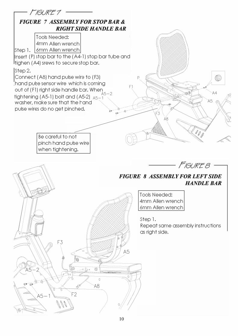
Note: Make Sure when the computer is being placed on the housing, that the wires are pushed back into the (E1) central support tube to prevent pinching a wire when the computer is being locked into place.Step 1. Remove (G2) screws from the back of the console bottom housing.Step 2. Connect (E3) computer wire and (E4) heart rate wire to (G) computer console.Step 3. Slide (G) computer console onto (E1) central support tube. Using (G2) screws, fasten screws to back of computer bracket.
10
A5
A5-1
A5-2
A4A5-1
A5-2
A5

11
H1

12
Recumbent Seat Adjustments
How to transport the bike
How to adjust the Seat Pad
To adjust the seat railaccording to a user’sheight, pull up on the stopbar (P) and set the seat tothe most comfortablelocation which allows therider to have a smooth andcomfortable motion. Theproper way to cycle is tohave the knees slightly bentduring the furthest pedalrotation.
If the machine needs to be transported to a different location, stand at the frontof the machine and push down on the front handle bars until the weight of themachine is transferred to the transport wheels and the rear of the machine is inthe air. You can now easily move the machine to a new location. Gently set themachine down at its new location.
Pull UpPull Down

13
How to power your machine
It is always recommended that the unit’s AC adaptor be plugged into a surge protector orunplugged after every use to prevent electrical damage.The machine has an electrical inlet at the rear, where the unit can run on an ACadaptor. It is recommended that this adaptor be plugged into a surge protector, which is notshown below. AC Adaptor specification AC Adapter US standard with maximum wattage 4.5W - I/P: 120V AC 60HZ - O/P: (DC6V 1000MA)
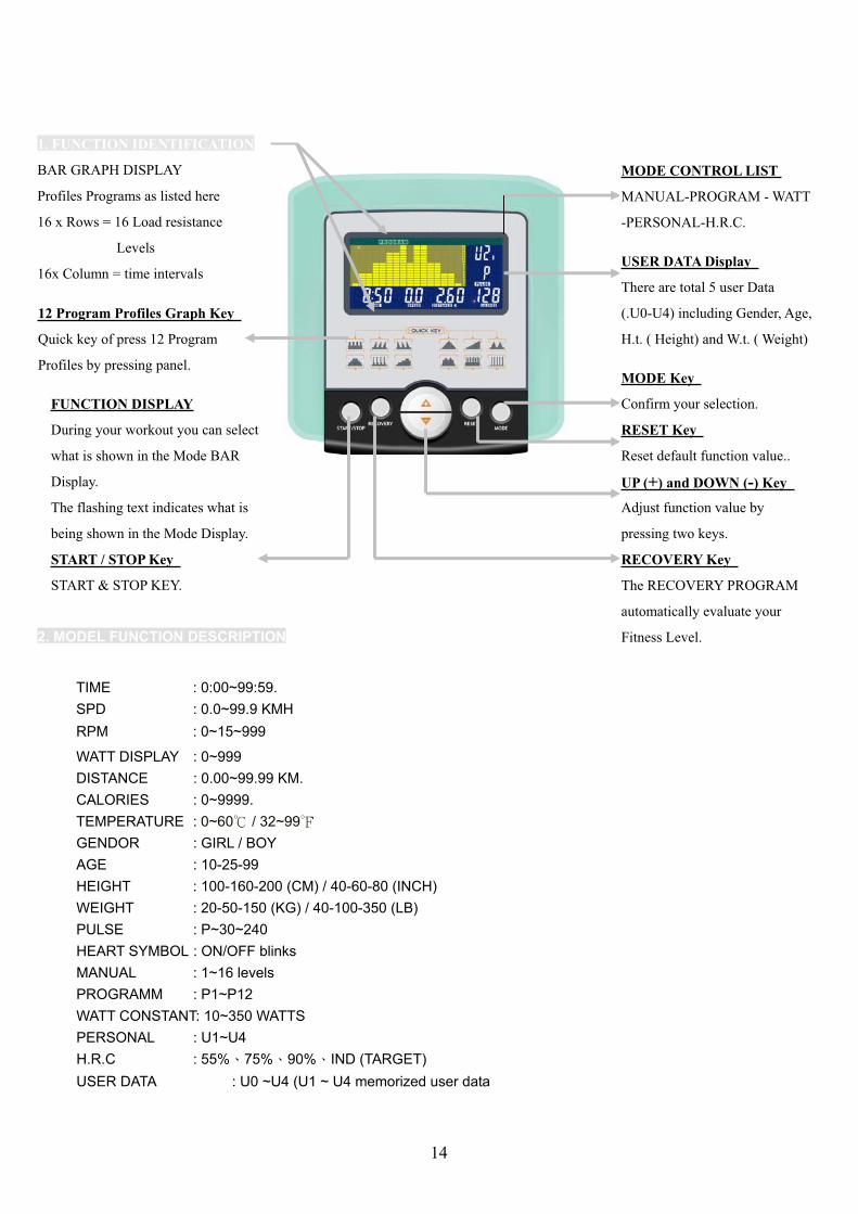
1. FUNCTION IDENTIFICATION
BAR GRAPH DISPLAY
Profiles Programs as listed here
16 x Rows = 16 Load resistance
Levels
16x Column = time intervals
2. MODEL FUNCTION DESCRIPTION
TIME : 0:00~99:59.SPD : 0.0~99.9 KMHRPM : 0~15~999
WATT DISPLAY : 0~999DISTANCE : 0.00~99.99 KM.CALORIES : 0~9999.TEMPERATURE : 0~60 / 32~99GENDOR : GIRL / BOYAGE : 10-25-99HEIGHT : 100-160-200 (CM) / 40-60-80 (INCH)WEIGHT : 20-50-150 (KG) / 40-100-350 (LB)PULSE : P~30~240HEART SYMBOL : ON/OFF blinksMANUAL : 1~16 levelsPROGRAMM : P1~P12WATT CONSTANT: 10~350 WATTSPERSONAL : U1~U4H.R.C : 55% 75% 90% IND (TARGET)USER DATA : U0 ~U4 (U1 ~ U4 memorized user data
MODE CONTROL LIST
MANUAL-PROGRAM - WATT
-PERSONAL-H.R.C.
USER DATA Display
There are total 5 user Data
(.U0-U4) including Gender, Age,
H.t. ( Height) and W.t. ( Weight)
12 Program Profiles Graph Key
Quick key of press 12 Program
Profiles by pressing panel.
FUNCTION DISPLAY
During your workout you can select
what is shown in the Mode BAR
Display.
The flashing text indicates what is
being shown in the Mode Display.
MODE Key
Confirm your selection.
RESET Key
Reset default function value..
UP (+) and DOWN (-) Key
Adjust function value by
pressing two keys.
RECOVERY Key
The RECOVERY PROGRAM
automatically evaluate your
Fitness Level.
START / STOP Key
START & STOP KEY.
14
3. POWER ON
1. Plug in 6V 1A power Adaptor to right country socket and connect the I / L PIN to Fitness equipment.
2. When stay in U0~U4, only there is pulse input, then PULSE symbol on the right in window will operate to display
automatically as per H.R.C.: If pulse maximum value is set, then the function cancel automatically.
3. Recovery To test user’s heart recovery extent in fixed time, time will be 1 minute.
4. User Data 5 groups for user setting U0~U4, every user can set gender age height and weight, however when power
off or TOTAL RESET,U0 setting files will be cleaned and reset and U1-U4 setting values will be saved permanently.
5. USER SETTING VALUE MEMORY: setting files memory (TIME DISTANCE CALORIES PULSE setting value)&the
function setting value(set value which used last time or changed manual load set value: or PROGRAM PX(1-12)…Etc. it
can only remember one of them. For instance: WATT CONSTANT SET VALUE: or PERSONAL program), U1~U4 fours
groups altogether.
;4. CONTROL MODE DESCRIPTIONA. MANUAL Set the resistance level by using the dot matrix display then (if required) to set function value.
TIME/DISTANCE / CALORIES / PULSE; the function value will be counting down from pre-setting number to 0. And thenpress ST/STOP to START manual program at anytime to start your workout.
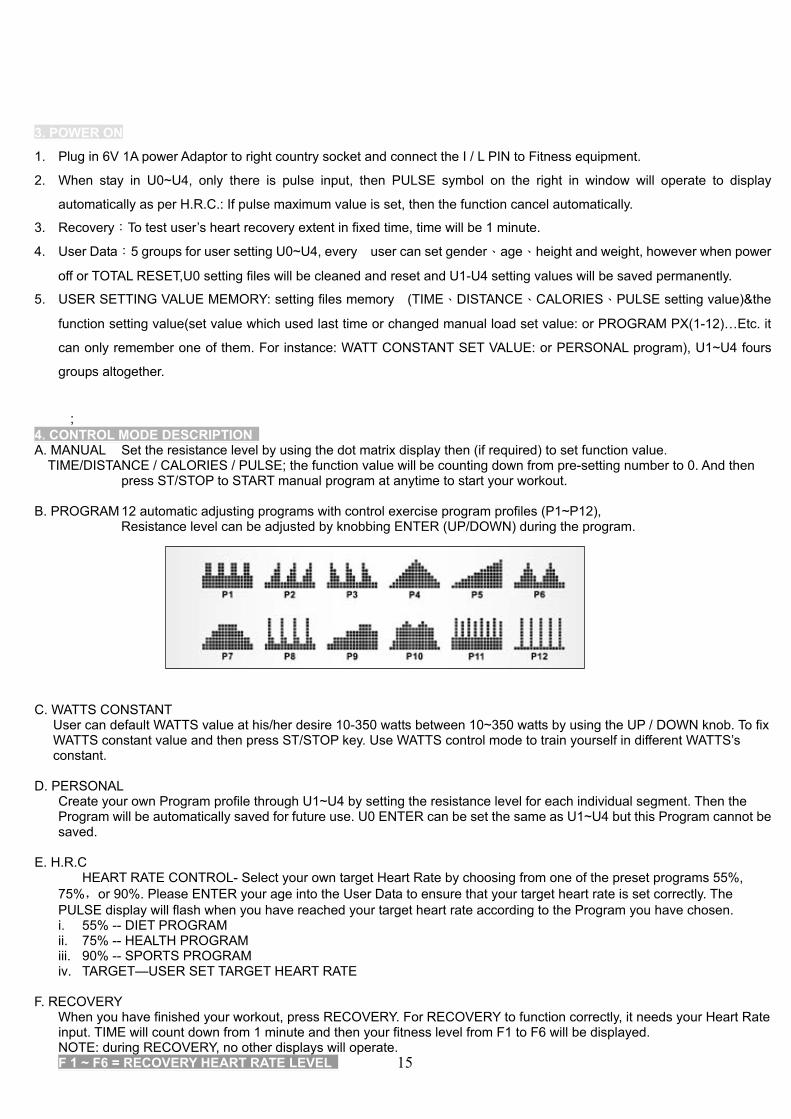
B. PROGRAM 12 automatic adjusting programs with control exercise program profiles (P1~P12),Resistance level can be adjusted by knobbing ENTER (UP/DOWN) during the program.
C. WATTS CONSTANTUser can default WATTS value at his/her desire 10-350 watts between 10~350 watts by using the UP / DOWN knob. To fixWATTS constant value and then press ST/STOP key. Use WATTS control mode to train yourself in different WATTS’sconstant.
D. PERSONALCreate your own Program profile through U1~U4 by setting the resistance level for each individual segment. Then theProgram will be automatically saved for future use. U0 ENTER can be set the same as U1~U4 but this Program cannot besaved.
E. H.R.CHEART RATE CONTROL- Select your own target Heart Rate by choosing from one of the preset programs 55%,
75% or 90%. Please ENTER your age into the User Data to ensure that your target heart rate is set correctly. ThePULSE display will flash when you have reached your target heart rate according to the Program you have chosen.i. 55% -- DIET PROGRAMii. 75% -- HEALTH PROGRAMiii. 90% -- SPORTS PROGRAMiv. TARGET—USER SET TARGET HEART RATE
F. RECOVERYWhen you have finished your workout, press RECOVERY. For RECOVERY to function correctly, it needs your Heart Rateinput. TIME will count down from 1 minute and then your fitness level from F1 to F6 will be displayed.NOTE: during RECOVERY, no other displays will operate.F 1 ~ F6 = RECOVERY HEART RATE LEVEL 15

UM6688-7Operating ENTERS:1. User press H.R.C key to start the H.R.C.2. Get the result from F1 - F6.
Condition Score Heart Rate
Excellent F1 Above 50Good F2 40 ~ 49
Average F3 30 ~ 39Fair F4 20 ~ 29Poor F5 10 ~ 19
Very Poor F6 Under 10
G. USER DATA :U0~U4 are user’s Personal Programs (refer Personal). Users should ENTER their gender, age, height and weight. Only data
for U1 to U4 will be saved. U0 is for casual users.
7 BUILT-IN Heart Rate Receiver with chest Belt
The computer with built-in Heart Rate receiver , the user can put on chest belt to detect the Heart Rate beat.; How to
put on chest belt, please refer Chest Belt user manual.
TIPS1. Option: Plug in AC Adaptor (6 VOLT, 1 A).2. Keep moisture away from computer.
16

Warranty Card – LifeCore Fitness Inc. LC-950RB Recumbent BikeThis Limited Warranty applies in the United States to products manufactured or distributed by LifeCore Fitness, Inc. under the LifeCore brand name. The warranty period for the original purchaser is (lifetime) on the frame against defects in materials and workmanship under normal use and conditions (excluding expendable parts such as paint & finish). Home 5 years parts, 1 year labor, light commercial 2 years parts 90 days labor warranty against manufacturer defects. This warranty does not cover wear and tear items such as, but not limited to, transportation wheels, foot pedals, rubber grips, plastic end caps, scratched parts, broken covers, and cosmetic damage. Wear items pertain to components that might need to be replaced due to normal wear and tear as a result of normal usage. Labor warranty does not cover improper installation, alterations and/or modifications, misuse, abuse, accident, improper maintenance, noises such as: squeaks, clunks, thumps from a result of poor or lack thereof preventive maintenance. LifeCore warrants that the product you have purchased for personal, family household use from LifeCore, or from an authorized LifeCore reseller, is free from defects in materials or workmanship under normal use during the warranty period. In order to validate the warranty this product must have been registered through LifeCore Fitness Inc., and/or a copy of the proof of purchase, and serial number must be presented at time of service. If these items are not presented at the time of requesting parts or service LifeCore Fitness Inc. will not cover any warranty set forth. During the warranty period LifeCore will at no additional charge, repair or replace (at LifeCore option) the part or product if it becomes defective, malfunctions, or otherwise fails to conform with this Limited Warranty under normal personal use as determined by a LifeCore technician. Any labor cost above the amount allocated by LifeCore is the responsibility of the original purchaser. If a product is shipped, delivered or transported to an area that is not a LifeCore Fitness Inc’s distribution area or is out of a serviceable area, it is the purchaser’s sole responsibility to find service and pay for any feesassociated with servicing of a product out of LifeCore Fitness distribution or serviceable area. To obtain warranty service, you must contact the original place of purchase. In repairing the product, LifeCore may replace defective parts, or at the option of LifeCore, serviceable used parts that are equivalent to the new parts in performance. All exchanged parts and products replaced under this warranty will become the property of LifeCore. LifeCore reserves the right to change manufacturers of any parts to cover any existing warranty. Any parts determined to be defective must be returned to LifeCore to obtain warranty service. You must prepay any shipping charges, export taxes, custom duties and taxes, or any other charges associated with transportation of the parts or product. In addition, you are responsible for insuring any parts orproduct shipped or returned. You assume the risk of loss during shipment. Any evidence of alteration, erasing or forgery of proof-of-purchase documents will be cause to void this Limited Warranty. This warranty does not extend to any product not purchased from LifeCore or from an authorized LifeCore reseller. This Limited Warranty does not extend to any product that has been damaged or rendered defective; (a) as a result of accident, misuse, or abuse; (b) by the use of parts not manufactured or sold by LifeCore; (c) by modification of the Product or normal wear and tear; (d) operation on incorrect power supplies; or (e) as a result of service by anyone other than LifeCore, or an authorized LifeCore service provider. Product on which the serial number has been defaced or removed is not eligible for warranty service. Should any Product be submitted for warranty service be found ineligible, an estimate of repair cost will be furnished and the repair will be made ifrequested by you upon receipt of payment or acceptable arrangements for payment. LIFECORE MAKES NO OTHER WARRANTIES, EXPRESSED OR IMPLIED, INCLUDING ANY IMPLIED WARRANTIES OR MERCHANTABILITY AND FITNESS FOR A PARTICULAR PURPOSE. LIFECORE EXPRESSLY DISCLAIMS ALL WARRANTIES NOT STATED IN THIS LIMITED WARRANTY. NEITHER LIFECORE NOR ANY OF ITS AFFILIATES SHALL BE RESPONSIBLE FOR INCIDENTAL OR CONSEQUENTIAL DAMAGES. PLEASE SEND IN THE ATTACHED WARRANTY CARD WITHIN (10) DAYS OF PURCHASE TO REGISTER YOUR PRODUCT WITH LIFECORE FITNESS. THANK YOU FOR YOUR BUSINESS! PLEASE MAIL WARRANTY CARD TO: LIFECORE FITNESS, INC, 2575 Pioneer Ave. Suite 101. Vista, CA 92081. Phone (760)599-4555, Fax (760) 946-7602 or register online at lifecorefitness.com, Customer Service: 888-815-5559
LC-950RB Recumbent Bike Please Attach a Copy of the Original ReceiptFull Name: ____________________________________________________________________Address: ______________________________________________________________________City: ___________________________ State: ________ Zip Code: ________________________ Daytime Phone No.:____________________ Cell Phone No.:____________________________Email: ________________________________________________________________________Dealer Purchased from: __________________________________________________________Model: LC-950RB Bike Date Of Purchase: _________________________________Serial No._____________________________________Environment Placed: Residential Light Commercial Commercial