lifetime power energy harvesting development kit for ... · a complete development kit for...
TRANSCRIPT
Lifetime Power® Energy Harvesting
www.powercastco.com
©2013 Powercast Corporation
Lifetime Power® Energy Harvesting Development Kit for Battery Charging
P2110-EVAL-02
1
Powercast Technology Overview
• Delivers micro-power over distance using common radio waves
–microwatts(µW) to low milliwatts (mW)
• Green/CleanTech power solution
www.powercastco.com
©2013 Powercast Corporation
• Green/CleanTech power solution
– eliminates wires, simplifies installation
– reduces/eliminates battery replacement
– provides lifetime power
– hazardous material shipping & disposal costs reduced or eliminated
2

Why RF Power?
• Wire-free Operation
– Untethered placement and mobility
– Operates anywhere in range of a suitable RF power source
– One-to-many charging
• Reliable
www.powercastco.com
©2013 Powercast Corporation
• Reliable
– Power source is controlled/deterministic
– Available on demand
– Minimal effects from weather / time-of-day
• End product differentiation
– Sealable / waterproof
– Zero maintenance

A complete development kit for wirelessly charging batteries for micro-power applications.
P2110-EVAL-02
www.powercastco.com
©2013 Powercast Corporation
• Charging range of 40-45 feet with included patch antenna
• Charges multiple battery types and includes THINERGY® Micro-Energy Cell
• Connects to THINERGY ® ADP and includes TI eZ430-RF2500 wireless kit
4

Kit Components3-watt, 915MHz Powercaster™ Transmitter
TI eZ430-RF2500 Development Tool
www.powercastco.com
©2013 Powercast Corporation 5
Receiving Antennas
Battery Charging
Interface Board
P2110CSR Powerharvester ®
Evaluation Board
THINERGY®
Evaluation Card
THINERGY® ADP Interface Cable
End Device
Access Point
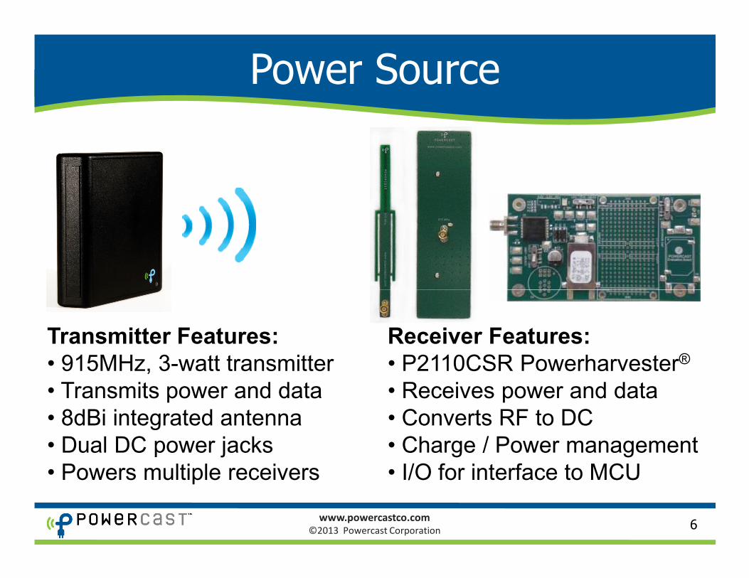
Power Source
www.powercastco.com
©2013 Powercast Corporation 6
Transmitter Features:
• 915MHz, 3-watt transmitter
• Transmits power and data
• 8dBi integrated antenna
• Dual DC power jacks
• Powers multiple receivers
Receiver Features:
• P2110CSR Powerharvester®
• Receives power and data
• Converts RF to DC
• Charge / Power management
• I/O for interface to MCU
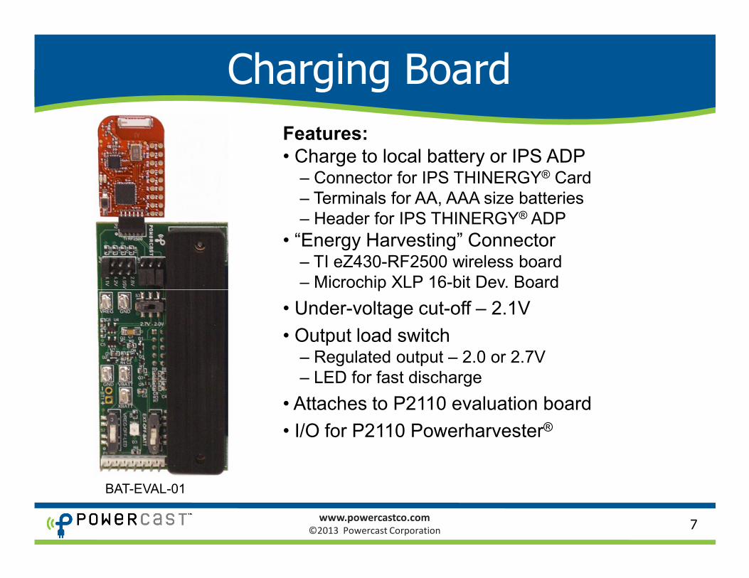
Charging Board
Features:
• Charge to local battery or IPS ADP– Connector for IPS THINERGY® Card
– Terminals for AA, AAA size batteries
– Header for IPS THINERGY® ADP
• “Energy Harvesting” Connector– TI eZ430-RF2500 wireless board
– Microchip XLP 16-bit Dev. Board
www.powercastco.com
©2013 Powercast Corporation 7
– Microchip XLP 16-bit Dev. Board
• Under-voltage cut-off – 2.1V
• Output load switch– Regulated output – 2.0 or 2.7V
– LED for fast discharge
• Attaches to P2110 evaluation board
• I/O for P2110 Powerharvester®
BAT-EVAL-01
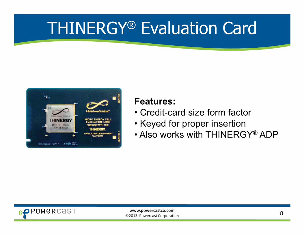
THINERGY® Evaluation Card
Features:
• Credit-card size form factor
www.powercastco.com
©2013 Powercast Corporation 8
• Keyed for proper insertion
• Also works with THINERGY® ADP

Charging to THINERGY® ADP
Antenna
P2110CSR Powerharvester®
8-wire Cable
THINERGY®
Both “Pass-Thru” and “Gated”
modes supported on ADP
www.powercastco.com
©2013 Powercast Corporation 9
P2110CSR Powerharvester®
Evaluation Board
Charging Board
THINERGY®
Application
Development
Platform
THINERGY ®
Evaluation CardTHINERGY® ADP is sold by Infinite Power Solutions

TI eZ430-RF2500 Wireless Kit
www.powercastco.com
©2013 Powercast Corporation
• Out-of-the-box application to demonstrate remote charging
• End device operates directly from Powercast Charging Board
• PC application and source code provided by Texas Instruments
10
http://focus.ti.com/docs/toolsw/folders/print/ez430-rf2500.html

More Information / Ordering
Product Listing
http://www.powercastco.com/products/development-kits/
Product Support Information
http://www.powercastco.com/resources/
Distributors – online ordering
P2110-EVAL-02
www.powercastco.com
©2013 Powercast Corporation 11
Distributors – online ordering
http://www.mouser.com/powercast/
http://www.FutureElectronics.com
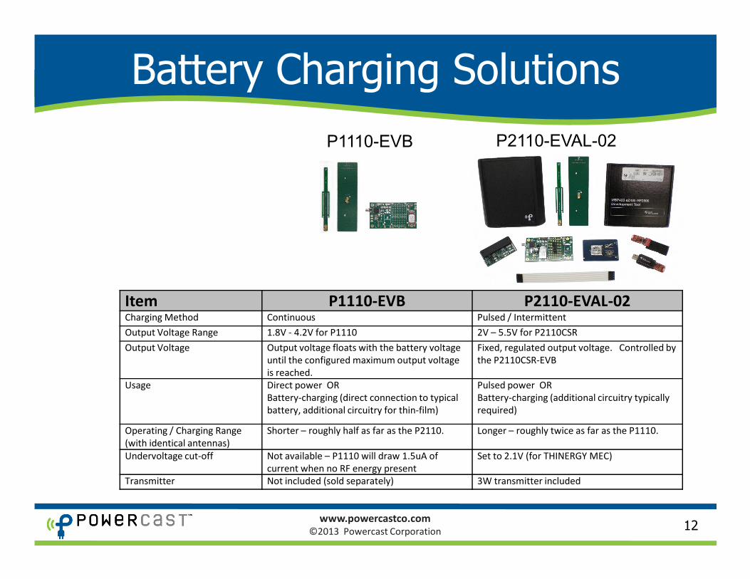
Battery Charging Solutions
P2110-EVAL-02P1110-EVB
Item P1110-EVB P2110-EVAL-02
www.powercastco.com
©2013 Powercast Corporation 12
Item P1110-EVB P2110-EVAL-02Charging Method Continuous Pulsed / Intermittent
Output Voltage Range 1.8V - 4.2V for P1110 2V – 5.5V for P2110CSR
Output Voltage Output voltage floats with the battery voltage
until the configured maximum output voltage
is reached.
Fixed, regulated output voltage. Controlled by
the P2110CSR-EVB
Usage Direct power OR
Battery-charging (direct connection to typical
battery, additional circuitry for thin-film)
Pulsed power OR
Battery-charging (additional circuitry typically
required)
Operating / Charging Range
(with identical antennas)
Shorter – roughly half as far as the P2110. Longer – roughly twice as far as the P1110.
Undervoltage cut-off Not available – P1110 will draw 1.5uA of
current when no RF energy present
Set to 2.1V (for THINERGY MEC)
Transmitter Not included (sold separately) 3W transmitter included