lift force sensor - royal institute of technologyluca/micro/wouter11.pdf · reciprocating pumps ....
TRANSCRIPT

Applied Microfluidics
Professor Wouter van der Wijngaart
Microsystem Technology Lab,
School of Electrical Engineering KTH Royal Institute of Technology
Email: [email protected]

KTH-EE-MST – Microfluidics – Wouter van der Wijngaart – spring 2009
Why downscaling?
Volume V ~ d3
Area A ~ d2
Length L ~ d
d

KTH-EE-MST – Microfluidics – Wouter van der Wijngaart – spring 2009
Why downscaling?
Volume V ~ d3
Area A ~ d2
Length L ~ d
1. Individual handling and manipulation of microscale objects in a liquid environment requires systems of the same magnitude order
d

KTH-EE-MST – Microfluidics – Wouter van der Wijngaart – spring 2009
Mic
roflu
idic
s N
anof
luid
ics
Volume Cube size Objects
1 ml=10-6 m3 1 cm “1 US teaspoon = 4.92892161 ml”
1 µl =10-9 m3 1 mm small insects, drizzle
rain
1 nl=10-12 m3
0.1 mm
Human Ovarian cell; Fly poop; limit of the naked eye.
1 pl=10-15 m3 10 µm Blood cells;
spermatozoids
1 fl =10-18 m3 1 µm Bacteria; limit of light
microscope
1 al =10-21 m3 0.1 µm Virus, colloids, large DNA
1 zl =10-24 m3 10 nm
carbon nano-tube; protein size; short DNA
1 yl=10-27 m3 1 nm raindrop nucleation
1 xl=10-30 m3 1 Å Small molecules
Small scale objects
Con
tinuu
m
brea
kdow
n
gas liquid
Continuum models
Molecular models
Quantum physics

Why downscaling?
Volume V ~ d3
Area A ~ d2
Length L ~ d
2. Handling and manipulation of very small sample volumes (<10 µl) requires system features of the same magnitude order
d

KTH-EE-MST – Microfluidics – Wouter van der Wijngaart – spring 2009
Mic
roflu
idic
s N
anof
luid
ics
Volume Cube size
1 ml=10-6 m3 1 cm
1 µl =10-9 m3 1 mm
1 nl=10-12 m3
0.1 mm
1 pl=10-15 m3 10 µm
1 fl =10-18 m3 1 µm
1 al =10-21 m3 0.1 µm
1 zl =10-24 m3 10 nm
1 yl=10-27 m3 1 nm
1 xl=10-30 m3 1 Å
Small Volumes
Con
tinuu
m
brea
kdow
n
gas liquid
Continuum models
Molecular models
Quantum physics
Inkjet print droplets ~50 pL
Smallest pipettes dispense ~0.5µL

KTH-EE-MST – Microfluidics – Wouter van der Wijngaart – spring 2009
Why downscaling?
Volume V ~ d3
Area A ~ d2
Length L ~ d
Downscaling leads to an increased area per volume:
A/V ~ 1/d
Surface related physical effects become dominant in the microscale
d

Examples of surface related effects in fluidics
Friction at the liquid-solid boundary: Zero slip at the wall results in laminar flow
Electro-fluidic interaction: Electric double layer related phenomena:
• Electro-osmotic flow • Electro-viscous effect • …

Why downscaling?
Volume V ~ d3
Area A ~ d2
Length L ~ d
d
Diffusion becomes a transport phenomenon of
importance

Diffusion as a transport mechanism
Diffusion is described by Fick’s first and second law (see Wikipedia for more information).
KTH-EE-MST – Microfluidics – Wouter van der Wijngaart – spring 2009
tDLD ⋅≈ 2
Diffusion length Diffusion constant
time
Molecule in H2O Typical D LD for 1 s LD for 100 s
N2 1e-6 2 mm 20 mm
Protein (100 kDa; 5 nm diameter)
1e-10 20 µm 200 µm

Why downscaling (fluidic) components?
Application
benefits from
downscaling
Application demands small size
• Monitoring in confined spaces (human body)
• Handling small volumes (DNA, cells, inkjet drops)
• Portability • Functional integration • …
Decreased cost • Manufacturing cost • Materials cost • Consumables reduction (high-
throughput screening) • …
Increased performance • Fast response • Large spatial gradient • Surface effects • Precision • …
Application does not benefit from
downscaling
Microfabrication technology: •Semiconductor manufacturing •Polymer microreplication
Large surface / volume ration
Low inertia

KTH-EE-MST – Microfluidic devices – Wouter van der Wijngaart – Spring 2009
Lecture outline
Classification of microfluidic components and systems Gas microvalves Inkjet printheads Micropumps Power-MEMS
Fuel cells Microcombustion systems
Examples of commercially available multifunctional microfluidic platforms PDMS based fluidic microfluidic platforms CD-based microfluidic platforms
Microfluidic solutions for diagnostic devices Micro-macro fluidic interfaces
Nebulisers ESI tips

KTH-EE-MST – Microfluidic devices – Wouter van der Wijngaart – Spring 2009
Bubblejet printhead principle
O’Horo et al, “Micro electro mechanical system technology for commercial thermal inkjet document output products,” Eurosensors X, Leuven, September 1996, pp. 431-435
Some typical figures: heater temp: 400°C drop velocity: 10 m/s drop volume: 100 pl pressure range:
bubble growth:10 - 40 atm
bubble collapse: 100 atm cycle frequency: 1 - 10
kHz

KTH-EE-MST – Microfluidic devices – Wouter van der Wijngaart – Spring 2009
Inkjet printheads - Examples

KTH-EE-MST – Microfluidic devices – Wouter van der Wijngaart – Spring 2009
Inkjet Printers – Monolythic system integration
Need for large data handling requires high level of integration !

KTH-EE-MST – Microfluidic devices – Wouter van der Wijngaart – Spring 2009
Group discussion
What limits the amount of pages/minute that a bubble jet printer can produce?
- - - …

KTH-EE-MST – Microfluidic devices – Wouter van der Wijngaart – Spring 2009
Lecture outline
Classification of microfluidic components and systems Gas microvalves Inkjet printheads Micropumps Power-MEMS
Fuel cells Microcombustion systems
Examples of commercially available multifunctional microfluidic platforms PDMS based fluidic microfluidic platforms CD-based microfluidic platforms
Microfluidic solutions for diagnostic devices Micro-macro fluidic interfaces
Nebulisers ESI tips

KTH-EE-MST – Microfluidic devices – Wouter van der Wijngaart – Spring 2009
Micropumps – a classification
[Krutzch et al.]

KTH-EE-MST – Microfluidic devices – Wouter van der Wijngaart – Spring 2009
Micropump applications
The following is a non-exhaustive list of used and suggested applications:
• Drug delivery (transdermal or implanted) • Fuel pump (Fuel cells) • Miniaturised diagnostic systems (Lab on a chip) • Space exploration:
– miniaturised instrumentation – propulsion
• IC cooling • …
Flow rate
Precision
Required characteristics

KTH-EE-MST – Microfluidic devices – Wouter van der Wijngaart – Spring 2009
Bubble valve pump
Freely adapted from [A planar laminar mixer, Evans et al, Berkeley]
Top to bottom net flow
Pump chamber
Bubble valve
Resistive heater

KTH-EE-MST – Microfluidic devices – Wouter van der Wijngaart – Spring 2009
Hydrolysis as actuator positive current dissociates the water
gas bubbles push out the liquid Negative current reduces the gas
liquid is sucked back 3 electrodes:
2 used for actuation (red, green) 2 used for conductivity measurement (green, blue)
[Böhm et al, Utwente, The Netherlands]

KTH-EE-MST – Microfluidic devices – Wouter van der Wijngaart – Spring 2009
Expandable bead actuators
[Griss et al, KTH-S3]
Initial volume
Expanded volume
V0 ~60V0
heat One-shot valve
One-shot pump
φ ≈ 10µm

KTH-EE-MST – Microfluidic devices – Wouter van der Wijngaart – Spring 2009
Expandable microspheres in PDMS
Mixing PDMS and Expancel® microspheres: XB-PDMS A thermally responsive PDMS composite
Large expansion (> 100%) Highly elastomeric Non-toxic and chemically inert Allows for e.g. soft lithography, casting, spinning… Highly integratable actuator
Heat to >70 C and remove cover
PDMS Microchannel Spin-on XB-PDMS
Solid substrate
[Samel et al., IEEE JMEMS (16) 2007]

KTH-EE-MST – Microfluidic devices – Wouter van der Wijngaart – Spring 2009
Expandable bead pumps
Movie
[B. Samel et al., KTH]

KTH-EE-MST – Microfluidic devices – Wouter van der Wijngaart – Spring 2009
Peristaltic pump principle 1
2
3
4
5
6
1
Other examples of peristaltic movements in nature:
Movement of worms and larves
Intestines pressing through food

KTH-EE-MST – Microfluidic devices – Wouter van der Wijngaart – Spring 2009
A peristaltic micropump example
J. G. Smits, “Piezoelectric Micropump with Three Valves Working Peristaltically,” Sensors and Actuators, vol.A21-A23 (1990) 203-206.

KTH-EE-MST – Microfluidic devices – Wouter van der Wijngaart – Spring 2009
Reciprocating Pumps A pump consisting of: 1. One pressure chamber enabling volume displacement (with at
one side most often a diaphragm actuator); 2. Flow directing elements at the inlet and outlet:
Mechanical valve Diffuser Nozzle Tesla valve …
supply
pump

KTH-EE-MST – Microfluidic devices – Wouter van der Wijngaart – Spring 2009 [Shoji et al., Microflow devices and systems, JMM 4 (1994), pp. 157-171]
Passive mechanical microvalves

KTH-EE-MST – Microfluidic devices – Wouter van der Wijngaart – Spring 2009
Reciprocating passive valve micropump
[R. Linneman et al., MEMS'98, Heidelberg]
[R. Zengerle et al., MEMS'95, Amsterdam]
[van de Pol et al., Sensors & Actuators, 1990]
Piezoelectrically actuated flap valve micropump
Electrostatically actuated flap valve micropump
Thermopneumatically actuated diaphragm valve micropump

KTH-EE-MST – Microfluidic devices – Wouter van der Wijngaart – Spring 2009
Lecture outline
Gas microvalves Inkjet printheads Micropumps Power-MEMS
Fuel cells Microcombustion systems
Examples of commercially available multifunctional microfluidic platforms PDMS based fluidic microfluidic platforms CD-based microfluidic platforms EWOD based “digital microfluidic” platforms Droplet-based platforms
Microfluidic solutions for diagnostic devices Micro-macro fluidic interfaces
Nebulisers ESI tips

KTH-EE-MST – Microfluidic devices – Wouter van der Wijngaart – Spring 2009
PDMS based microfluidic microfluidic platform
Fabrication
Single valve
System integration
Peristaltic pumps
[S. Quake et al., Stanford University] See also: www.fluidigm.com

KTH-EE-MST – Microfluidic devices – Wouter van der Wijngaart – Spring 2009
PDMS based microfluidic microfluidic platform
Interfacing requirements: • Input:
Sample Reagents
• Output: Reaction products Waste
• Pneumatic control lines: Integrated fluidic multiplexer: 2n+1 control lines steer n2 single valve units
More information: Stanford online lecture on http://www.youtube.com/watch?v=n0gmTc2wA3k

KTH-EE-MST – Microfluidic devices – Wouter van der Wijngaart – Spring 2009
Lecture outline
Gas microvalves Inkjet printheads Micropumps Power-MEMS
Fuel cells Microcombustion systems
Examples of commercially available multifunctional microfluidic platforms PDMS based fluidic microfluidic platforms CD-based microfluidic platforms EWOD based “digital microfluidic” platforms Droplet-based platforms
Microfluidic solutions for diagnostic devices Micro-macro fluidic interfaces
Nebulisers ESI tips

KTH-EE-MST – Microfluidic devices – Wouter van der Wijngaart – Spring 2009
Lab-on-CD Fabrication:
2-layer plastic CD molded microfluidic channels
Liquid manipulation forces Capillary force Spinning Coriolis forces
Integrated fluidic functionality: Valving, Dosing, Pumping, Mixing
Applications: MALDI preparation Cell incubation …
[Photographs: Gyros Microlabs, Upsala]
Loading ports in centre on top
Disc is open at the side See also: www.gyros.com

KTH-EE-MST – Microfluidic devices – Wouter van der Wijngaart – Spring 2009
Dosing in a rotational fluidic microfluidic platform
[illustrations: Gyros Microlabs, Upsala]
A hydrophobic break (in red) prevents liquid moving further into the microstructure.
Capillary force draws liquids into a distribution channel, filling a volume definition chamber.
As the CD spins, the distribution channel empties, leaving behind a precisely defined liquid volume.
A second spin, at higher speed, creates a g-force sufficient to drive the liquid over the hydrophobic break.

KTH-EE-MST – Microfluidic devices – Wouter van der Wijngaart – Spring 2009
Gyros Lab-CD technology
1. Liquid drawn in by capillary action.
2. Overflow channel activated at a low spin speed, removing excess liquid.
3. Volume (60 nl) defined within the chamber.
4. Defined volume moves through packed column by increasing spin speed.
[www.gyros.se]
Towards disc centre
Towards disc edge

KTH-EE-MST – Microfluidic devices – Wouter van der Wijngaart – Spring 2009
Lecture outline
Gas microvalves Inkjet printheads Micropumps Power-MEMS
Fuel cells Microcombustion systems
Examples of commercially available multifunctional microfluidic platforms PDMS based fluidic microfluidic platforms CD-based microfluidic platforms EWOD based “digital microfluidic” platforms Droplet-based platforms
Microfluidic solutions for diagnostic devices Micro-macro fluidic interfaces
Nebulisers ESI tips

EWOD: ElectroWetting On Dielectric
The water and solid electrode form the electrodes of a capacitor. When charging the capacitor, the capacitor will try to minimise
its energy by bringing charges close to eachother. It does this by spreading the water on the surface
KTH-EE-MST – Microfluidic devices – Wouter van der Wijngaart – Spring 2009
water
Hydrophobic dielectricum (typically Teflon)
electrode
Young-Lippman equation:

EWOD as transport mechanism
KTH-EE-MST – Microfluidic devices – Wouter van der Wijngaart – Spring 2009
[CJ Kim, UCLA] U=V U=V U=0
• When a droplet is in contact with several electrodes, it will move to the region with lowest contact angle.
• This can be used to move, split and merge droplets.
VIDEO: http://www.youtube.com/watch?v=_OJ_lorXUg4&NR=1

Some examples of EWOD platforms:
Digital microfluidic DNA analysis
Digital microfluidics for point-of-care testing
KTH-EE-MST – Microfluidic devices – Wouter van der Wijngaart – Spring 2009
http://www.youtube.com/watch?v=JvDZh8hmR84&feature=related
[Advanced Liquid Logic Inc]

KTH-EE-MST – Microfluidic devices – Wouter van der Wijngaart – Spring 2009
Lecture outline
Gas microvalves Inkjet printheads Micropumps Power-MEMS
Fuel cells Microcombustion systems
Examples of commercially available multifunctional microfluidic platforms PDMS based fluidic microfluidic platforms CD-based microfluidic platforms EWOD based “digital microfluidic” platforms Droplet-based platforms
Microfluidic solutions for diagnostic devices Micro-macro fluidic interfaces
Nebulisers ESI tips

Droplet based microfluidics
KTH-EE-MST – Microfluidic devices – Wouter van der Wijngaart – Spring 2009
[www.raindancetechnologies.com]
Fluorinated oil Fluorinated oil
Water-based bioreagents
~3000 droplets/second Every droplet = 1 bioreactor
High-throughput screening!

Droplet based microfluidics
Basic microfluidic operations: Droplet generation Droplet storage Droplet sorting Droplet merging
KTH-EE-MST – Microfluidic devices – Wouter van der Wijngaart – Spring 2009
Video: http://raindancetechnologies.com/technology/pcr-genomics-research.asp
Fluoresence based detection
Electrodes for dielectrophoretic sorting

Some examples of the use opf droplet based microfluidics
Major application: high throughput drug screening Screening for directed protein evolution [Agresti et al.,
PNAS, vol 107, no 9, 2010, 4004-4009] Culture mamalian cells and entire animals (C. Elegans)
on chip. [Clausell-Tormos et al., Chemistry & Biology 15, 427–437, 2008]
KTH-EE-MST – Microfluidic devices – Wouter van der Wijngaart – Spring 2009
egg worm larvae C. Elegans:

KTH-EE-MST – Microfluidic devices – Wouter van der Wijngaart – Spring 2009
Lecture outline
Classification of microfluidic components and systems Gas microvalves Inkjet printheads Micropumps Power-MEMS
Fuel cells Microcombustion systems
Examples of commercially available multifunctional microfluidic platforms PDMS based fluidic microfluidic platforms CD-based microfluidic platforms
Microfluidic solutions for diagnostic devices Micro-macro fluidic interfaces
Nebulisers ESI tips

KTH-EE-MST – Microfluidic devices – Wouter van der Wijngaart – Spring 2009
Microfluidic solutions for label-free diagnostic sensors
Wouter van der Wijngaart
Microsystem Technology Lab, KTH – the Royal Institute of Technology,
Stockholm, SWEDEN
Lab on Chip

KTH-EE-MST – Microfluidic devices – Wouter van der Wijngaart – Spring 2009
Collaborators: Work on narcotics detection platform:
Thomas Frisk, Wouter van der Wijngaart, Göran Stemme (KTH – the Royal Institute of Technology)
David Rönnholm, Per Månsson, Lars Eng (Biosensor Applications, Stockholm, Sweden)
Work on virus detection platform: Niklas Sandström, Thomas Frisk, Göran Stemme Wouter
van der Wijngaart, (KTH – the Royal Institute of Technology)
Hans Wigzell (Karolinska Institutet) Lennart Svensson (Linköping University)
Work on integrated microfluidic actuators platform:
Björn Samel, Niklas Roxhed, Patrick Griss, Göran Stemme (KTH – the Royal Institute of Technology)
KTH-EE-MST – Microfluidic devices – Wouter van der Wijngaart – Spring 2009
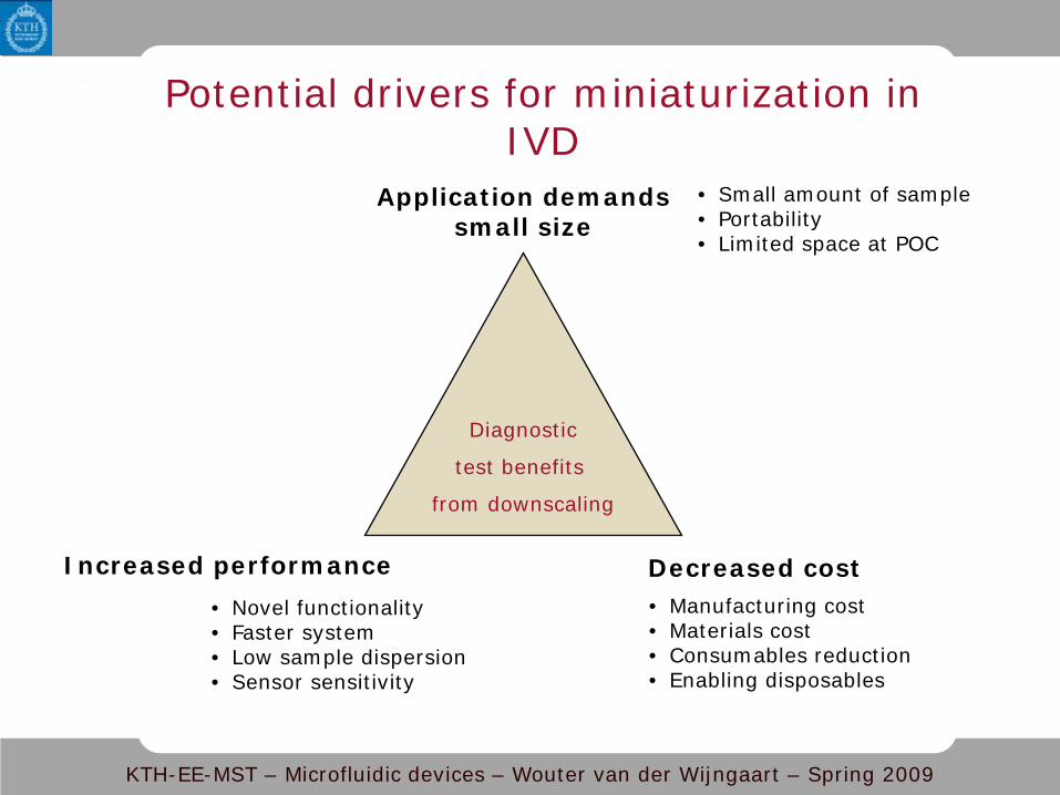
Potential drivers for miniaturization in IVD
Diagnostic
test benefits
from downscaling
Application demands small size
• Small amount of sample • Portability • Limited space at POC
Decreased cost • Manufacturing cost • Materials cost • Consumables reduction • Enabling disposables
Increased performance • Novel functionality • Faster system • Low sample dispersion • Sensor sensitivity

KTH-EE-MST – Microfluidic devices – Wouter van der Wijngaart – Spring 2009
Miniaturization enablers
Diagnostic
test benefits
from downscaling
Application demands small size
• Small amount of sample • Portability • Limited space at POC
Decreased cost • Manufacturing cost • Materials cost • Consumables reduction • Enabling disposables
Increased performance • Novel functionality • Faster system • Low sample dispersion • Sensor sensitivity
Microsystem manufacturing • Semiconductor manufacturing • Polymer microreplication • Functional integration
Phys. laws of scaling • Low inertia: fast response • Short distance:
• Fast transport • Diffusive transport
• Large surface/volume ratio: • Surface tension • Surface interactions • Laminar flow • …

KTH-EE-MST – Microfluidic devices – Wouter van der Wijngaart – Spring 2009
Generic microfluidic solutions for improved analyte transport
Droplet-borne sample Air-borne sample
On-chip storage of buffer/reagents/calibrant
Surface-based transducer
On-chip fluid transport solutions
Self-contained waste
Generic LOC

KTH-EE-MST – Microfluidic devices – Wouter van der Wijngaart – Spring 2009
Example: Miniaturisation of a narcotics detection instrument
1,5 cm
50 cm
[www.biosensor.se]
Functionality: 5 x faster
Cost: Less material Less assembly
100 x less consumables
Size: 50.000 x smaller

KTH-EE-MST – Microfluidic devices – Wouter van der Wijngaart – Spring 2009
Example: mass transport in a narcotics detection instrument
[www.biosensor.se]

KTH-EE-MST – Microfluidic devices – Wouter van der Wijngaart – Spring 2009
Example: narcotics detection immunoassay
[www.biosensor.se]
Ag
Load heavy Ab
QCM sensor surface
Add narcotic sample
Ab release in competitive assay Bind heavy Ab
Ab

KTH-EE-MST – Microfluidic devices – Wouter van der Wijngaart – Spring 2009
Example: Miniaturisation of a narcotics detection instrument
NO
NC
1
23 4
56
NC
waste PBS

KTH-EE-MST – Microfluidic devices – Wouter van der Wijngaart – Spring 2009
Phase 1 of miniaturisation
Reduce tubing Reduce sample transport time Reduce tubing reduce dispersion Reduce costs of valves and pumps
NO
NC
1
23 4
56
NC
waste PBS
replace

KTH-EE-MST – Microfluidic devices – Wouter van der Wijngaart – Spring 2009
waste PBS
Phase 1 of miniaturisation
1*2 cm2 microfluidic interface chip
[Frisk et al., Lab Chip 6, 2006]

KTH-EE-MST – Microfluidic devices – Wouter van der Wijngaart – Spring 2009
Phase 1 of miniaturisation
1*2 cm2 microfluidic interface chip
4 QCM transducers with selective immunoassay
pump AB solution for “resetting” the sensors
PBS waste
[Frisk et al., Lab Chip 6, 2006]

KTH-EE-MST – Microfluidic devices – Wouter van der Wijngaart – Spring 2009
Interfacing principle
W =
1cm
Stainless steel tube interface
Teflon fluid manifold
“wet” silicon adsorption
area
PBS in sample out
Teflon fluid manifold
L ≈ 1,2 cm
PMMA support
40 µm
50 µ
m
40 µm [Frisk et al., proc. Transducers, 2005]

KTH-EE-MST – Microfluidic devices – Wouter van der Wijngaart – Spring 2009
Air
50 µm
40 µm 40 µm
Si substrate
Pair
Pliquid
Pair > Pliquid
Liquid
Microstructured interface design Surface tension provides a robust interface
d
dPP liquidair
γ∝−
[Frisk et al., Lab Chip 6, 2006]
pilla
r
pilla
r
pilla
r
pilla
r
pilla
r

KTH-EE-MST – Microfluidic devices – Wouter van der Wijngaart – Spring 2009
50 µm
40 µm 40 µm
Si substrate
Pair
Pliquid
Pair < Pliquid
Liquid
Microstructured interface design
d
Air
Surface tension provides a robust interface d
PP liquidairγ
∝−
[Frisk et al., Lab Chip 6, 2006]
pilla
r
pilla
r
pilla
r
pilla
r
pilla
r
MOVIE

KTH-EE-MST – Microfluidic devices – Wouter van der Wijngaart – Spring 2009
Driving, sensing, control and interface electronics
QCM sensor array
Reference
Cocaine
Cocaine
Heroin
Heroin
Interface
[Frisk et al., proc. Transducers, 2005]

KTH-EE-MST – Microfluidic devices – Wouter van der Wijngaart – Spring 2009
Driving, sensing, control and interface electronics
QCM sensor array
Reference
Cocaine
Cocaine
Heroin
Heroin
Interface
100 ng heroin 5 s 270°C
-10
0
10
20
30
40
50
60
70
0 50 100 150 200 250
Time [/s]
∆f [/Hz]
Cell 1 Cocaine Cell 2 Heroin Cell 3 Cocaine Cell 4 Heroin
50 ng cocaine 5 s 270°C
-10
0
10
20
30
40
50
60
70
0 50 100 150 200 250
Time [/s]
∆f [/Hz]
Cell 1 Cocaine Cell 2 Heroin Cell 3 Cocaine Cell 4 Heroin
[Frisk et al., proc. Transducers, 2005]

KTH-EE-MST – Microfluidic devices – Wouter van der Wijngaart – Spring 2009
Phase 1 enablers
Diagnostic
test benefits
from downscaling
Application demands small size
• Small amount of sample • Portability • Limited space at POC
Decreased cost • Manufacturing cost • Materials cost • Consumables reduction • Enabling disposables
Increased performance • Novel functionality • Faster system • Low sample dispersion • Sensor sensitivity
Microsystem manufacturing • Semiconductor manufacturing • Polymer microreplication • Functional integration
Phys. laws of scaling • Low inertia: fast response • Short distance:
• Fast transport • Diffusive transport
• Large surface/volume ratio: • Surface tension • Surface interactions • Laminar flow • …

KTH-EE-MST – Microfluidic devices – Wouter van der Wijngaart – Spring 2009
Part 1 Device improvements
Sample introduction without introducing air bubbles
Transport time interface transducer: 60s 30s
Sample dispersion during transport strongly reduced
System cost is strongly reduced
[Frisk et al., proc. IEEE MEMS, 2007]

KTH-EE-MST – Microfluidic devices – Wouter van der Wijngaart – Spring 2009
Phase 2 of miniaturisation
1*2 cm2 microfluidic interface chip
4 QCM transducers with selective immunoassay
pump AB solution for “resetting” the sensors
PBS waste
INTEGRATE
[Frisk et al., proc. IEEE MEMS, 2007]

KTH-EE-MST – Microfluidic devices – Wouter van der Wijngaart – Spring 2009
Phase 2 of miniaturisation
Put the interface on top of the QCM
Fluidic ports
Electrical ports
Gold electrodes
Sample interface
Gold electrodes
Fluid channel
Polymer macrolon cap
QCM
VCAF
Silicon substrate
Buf
fer
in /
w
aste
out
sample + AB interface
Gold electrode Fluid channel
500 µm
50 µm
3,5 mm
15 mm
Cross-sectional view
Exploded view
[Frisk et al., proc. IEEE MEMS, 2007]

KTH-EE-MST – Microfluidic devices – Wouter van der Wijngaart – Spring 2009
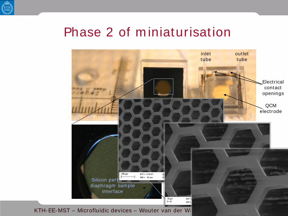
Phase 2 of miniaturisation inlet tube
outlet tube
QCM electrode
Electrical contact
openings
Silicon perforated diaphragm sample
interface
25 µm
KTH-EE-MST – Microfluidic devices – Wouter van der Wijngaart – Spring 2009
Phase 2 of miniaturisation inlet tube
outlet tube
QCM electrode
Electrical contact
openings
Silicon perforated diaphragm sample
interface
25 µm

KTH-EE-MST – Microfluidic devices – Wouter van der Wijngaart – Spring 2009
Cocaine detection inlet tube
outlet tube
QCM electrode
Electrical contact
openings
Silicon perforated diaphragm sample
interface
25 µm

KTH-EE-MST – Microfluidic devices – Wouter van der Wijngaart – Spring 2009
Norovirus detection
Freq
uenc
y
9996500
9997000
9997500
9998000
23100 24100 25100 26100 27100 28100
10008500
10009000
10009500
10010000
0 1000 200010008000
10008500
10009000
10009500
2000 3000
AB binding BSA blocking VLP on non-specific AB
2x VLP on specific AB
Freq
uenc
y Fr
eque
ncy
∆f ~ 200Hz
∆f ~ 150Hz ∆f ~ 15Hz
∆f ~ 200Hz
∆f ~ 80Hz

KTH-EE-MST – Microfluidic devices – Wouter van der Wijngaart – Spring 2009
Phase 2 additional enablers
Diagnostic
test benefits
from downscaling
Application demands small size
• Small amount of sample • Portability • Limited space at POC
Decreased cost • Manufacturing cost • Materials cost • Consumables reduction • Enabling disposables
Increased performance • Novel functionality • Faster system • Low sample dispersion • Sensor sensitivity
Microsystem manufacturing • Semiconductor manufacturing • Polymer microreplication • Functional integration
Phys. laws of scaling • Low inertia: fast response • Short distance:
• Fast transport • Diffusive transport
• Large surface/volume ratio: • Surface tension • Surface interactions • Laminar flow • …

KTH-EE-MST – Microfluidic devices – Wouter van der Wijngaart – Spring 2009
Part 2 Device improvements
Transport time interface transducer is minimised
Sample dispersion eliminated
Buffer flow: 100µL/min 2,5 µL/min
Cost system assembly is further reduced
[Frisk et al., proc. IEEE MEMS, 2007]

KTH-EE-MST – Microfluidic devices – Wouter van der Wijngaart – Spring 2009
Phase 3 of integration
Integrated microsensor
pump
AB solution for “resetting” the sensors
PBS waste
INTEGRATE AIRBORNE SAMPLING
[Sandström et al., proc. MicroTAS, 2007]

KTH-EE-MST – Microfluidic devices – Wouter van der Wijngaart – Spring 2009
ElectroHydroDynamic (EHD) airborne sample acquisition
This image cannot currently be displayed.
[Sandström et al., proc. MicroTAS, 2007]
MOVIE

KTH-EE-MST – Microfluidic devices – Wouter van der Wijngaart – Spring 2009
EHD airborne particle collection

KTH-EE-MST – Microfluidic devices – Wouter van der Wijngaart – Spring 2009
Phase 4 of miniaturisation
microfluidic interface chip AB solution for “resetting” the sensors
PBS waste
MINIATURISE
pump
[Roxhed et al., J. Micromech. Microeng, (dec) 2006]

KTH-EE-MST – Microfluidic devices – Wouter van der Wijngaart – Spring 2009
Integrated pumps and valves: Expandable Microspheres
Consist of polymer shells encapsulating liquid hydrocarbons
Expancel® Microspheres expand upon heat Shell softens, Hydrocarbon changes phase, Volume increases
Properties:
Expansion up to 60 times Expansion starts at 70°C Chemically inert Irreversible expansion
10 µm
40 µm

KTH-EE-MST – Microfluidic devices – Wouter van der Wijngaart – Spring 2009
Continuous liquid dispensing
[Roxhed et al., J. Micromech. Microeng, (dec) 2006]
1 cm
XB-glycerine paste
Heater contact
Dispensed liquid

KTH-EE-MST – Microfluidic devices – Wouter van der Wijngaart – Spring 2009
Continuous liquid dispensing
[Roxhed et al., J. Micromech. Microeng, (dec) 2006]
Key characteristics: 100 µL dispensed volume Flow rate: 1-2400 µL/h Delivery against 75kPa (=7.5m water) Low cost
Unexpanded paste on heater
Paste expanded in liquid
container
Paste freely expanded
Dispensed volume/time

KTH-EE-MST – Microfluidic devices – Wouter van der Wijngaart – Spring 2009
Phase 5 of miniaturisation
microfluidic interface chip AB solution for “resetting” the sensors
PBS waste
INTEGRATE
pump
[Samel et al., Biomedical Microdevices, 9 (1), 2007]

KTH-EE-MST – Microfluidic devices – Wouter van der Wijngaart – Spring 2009
Expandable microspheres in PDMS
Mixing PDMS and Expancel® microspheres: XB-PDMS A thermally responsive PDMS composite
Large expansion (> 100%) Highly elastomeric Non-toxic and chemically inert Allows for e.g. soft lithography, casting, spinning… Highly integratable actuator
Heat to >70 C and remove cover
PDMS Microchannel Spin-on XB-PDMS
Solid substrate
[Samel et al., IEEE JMEMS (16) 2007]

KTH-EE-MST – Microfluidic devices – Wouter van der Wijngaart – Spring 2009
Single-use pumps and valves
Picture sequence showing the release of 25nl of liquid from a reservoir
Picture sequence of the valve in its open (a) and closed (b) state.
• Pump • Valve
[Samel et al., Biomedical Microdevices, 9 (1), 2007]

KTH-EE-MST – Microfluidic devices – Wouter van der Wijngaart – Spring 2009
Dosing, transportation and merging of nanoliter volumes
Movie

KTH-EE-MST – Microfluidic devices – Wouter van der Wijngaart – Spring 2009
On-chip fluid loading, storage and dispensing
Close valve
aspiration
Create channel
dispensing
[Samel et al., proc. MicroTAS, 2007]
MOVIE

KTH-EE-MST – Microfluidic devices – Wouter van der Wijngaart – Spring 2009
XB microfluidic dispensers
Delivery time
Dispensing volume
10 nL
100 nL
1 µL
10 µL
100 µL
1 s 1 min 1 h
x
x x
Transdermal Drug delivery Dye Lasers
LOC applications

KTH-EE-MST – Microfluidic devices – Wouter van der Wijngaart – Spring 2009
Phase 2 additional enablers
Diagnostic
test benefits
from downscaling
Application demands small size
• Small amount of sample • Portability • Limited space at POC
Decreased cost • Manufacturing cost • Materials cost • Consumables reduction • Enabling disposables
Increased performance • Novel functionality • Faster system • Low sample dispersion • Sensor sensitivity
Microsystem manufacturing • Semiconductor manufacturing • Polymer microreplication • Functional integration
Phys. laws of scaling • Low inertia: fast response • Short distance:
• Fast transport • Diffusive transport
• Large surface/volume ratio: • Surface tension • Surface interactions • Laminar flow • …
KTH-EE-MST – Microfluidic devices – Wouter van der Wijngaart – Spring 2009
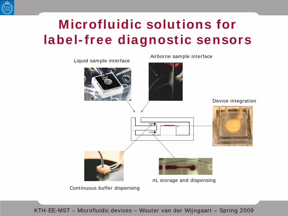
Microfluidic solutions for label-free diagnostic sensors
Liquid sample interface Airborne sample interface
Device integration
nL storage and dispensing Continuous buffer dispensing