liftech engineers have been providing stru ctural
TRANSCRIPT

Port and Terminal Technology 2010 Conference, Long Beach, CA October 6, 2010Arun Bhimani, Liftech Consultants Inc.
1
Liftech engineers have been providing structural engineering services to the container crane industry for over 45 years and have experience with many crane failures.
Once again, several catastrophic failures have occurred this year reminding the industry of the ever present risks.
This presentation will review a variety of accidents.

Port and Terminal Technology 2010 Conference, Long Beach, CA October 6, 2010Arun Bhimani, Liftech Consultants Inc.
We have organized the accidents into the three categories shown. Some overlap.
2
Port and Terminal Technology 2010 Conference, Long Beach, CA October 6, 2010Arun Bhimani, Liftech Consultants Inc.
We will explain an incident, discuss the causes or probable causes, discuss how the repairs were made, and suggest prevention and mitigation.
Our sources include first hand experience and information from the media and our contacts in the industry.
3
Port and Terminal Technology 2010 Conference, Long Beach, CA October 6, 2010Arun Bhimani, Liftech Consultants Inc.
4
We will start with some accidents that have occurred during operations.

Port and Terminal Technology 2010 Conference, Long Beach, CA October 6, 2010Arun Bhimani, Liftech Consultants Inc.
We will discuss four categories of operations related accidents.
5

Port and Terminal Technology 2010 Conference, Long Beach, CA October 6, 2010Arun Bhimani, Liftech Consultants Inc.
The most common accident during operations is vessel collisions.
The most common collision occurs between the vessel and crane boom.
The typical damage for a box girder boom with cross framing is presented first.
This collision occurred in New Jersey when a vessel berthed out of control. This type of collision causes severe damage.
The ship impacted the right girder pushing the boom laterally. Despite the severity of the damage, the crane frame was undamaged and the crane did not derail.
6
Port and Terminal Technology 2010 Conference, Long Beach, CA October 6, 2010Arun Bhimani, Liftech Consultants Inc.
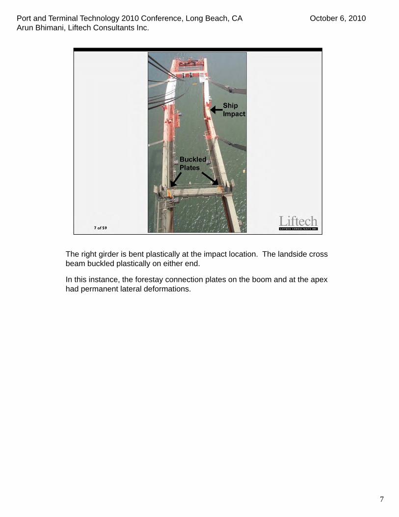
The right girder is bent plastically at the impact location. The landside cross beam buckled plastically on either end.
In this instance, the forestay connection plates on the boom and at the apex had permanent lateral deformations.
7

Port and Terminal Technology 2010 Conference, Long Beach, CA October 6, 2010Arun Bhimani, Liftech Consultants Inc.
This slide shows a close-up of the buckled portions of the landside cross tie, and the residual rotation at the upper boom hinge (lower left).
8
Port and Terminal Technology 2010 Conference, Long Beach, CA October 6, 2010Arun Bhimani, Liftech Consultants Inc.
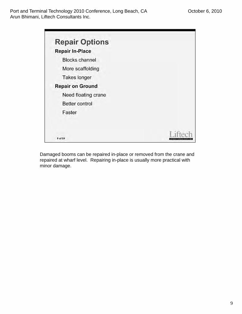
Damaged booms can be repaired in-place or removed from the crane and repaired at wharf level. Repairing in-place is usually more practical with minor damage.
9

Port and Terminal Technology 2010 Conference, Long Beach, CA October 6, 2010Arun Bhimani, Liftech Consultants Inc.
The first step in repair is to document the damage carefully to understand what happened, identify potential damage to other areas, and inspect the damage.
10
Port and Terminal Technology 2010 Conference, Long Beach, CA October 6, 2010Arun Bhimani, Liftech Consultants Inc.
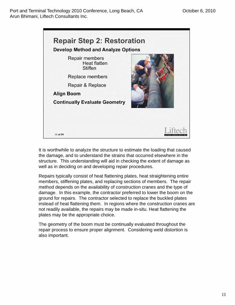
It is worthwhile to analyze the structure to estimate the loading that caused the damage, and to understand the strains that occurred elsewhere in the structure. This understanding will aid in checking the extent of damage as well as in deciding on and developing repair procedures.
Repairs typically consist of heat flattening plates, heat straightening entire members, stiffening plates, and replacing sections of members. The repair method depends on the availability of construction cranes and the type of damage. In this example, the contractor preferred to lower the boom on the ground for repairs. The contractor selected to replace the buckled plates instead of heat flattening them. In regions where the construction cranes are not readily available, the repairs may be made in-situ. Heat flattening the plates may be the appropriate choice.
The geometry of the boom must be continually evaluated throughout the repair process to ensure proper alignment. Considering weld distortion is also important.
11

Port and Terminal Technology 2010 Conference, Long Beach, CA October 6, 2010Arun Bhimani, Liftech Consultants Inc.
This is an example of replacing a web plate of the main boom girder at the collision location.
12

Port and Terminal Technology 2010 Conference, Long Beach, CA October 6, 2010Arun Bhimani, Liftech Consultants Inc.
These are examples of replacing buckled plates at the landside boom tie.
13

Port and Terminal Technology 2010 Conference, Long Beach, CA October 6, 2010Arun Bhimani, Liftech Consultants Inc.
The global geometry of the boom should be aligned after the damaged plates are removed.
The tie system shown in the left photo was used to rack the boom in plan to realign. The pipe strut was used with a hydraulic jack to separate and rotatethe boom girders.
After alignment is complete, plates are replaced. Accounting for weld distortion when installing new plates is important.
14

Port and Terminal Technology 2010 Conference, Long Beach, CA October 6, 2010Arun Bhimani, Liftech Consultants Inc.
Frame collisions are less frequent, but often cause significant damage.
Many collisions occur due to vessels berthing in inclement weather.
15

Port and Terminal Technology 2010 Conference, Long Beach, CA October 6, 2010Arun Bhimani, Liftech Consultants Inc.
This crane in Ecuador was knocked over by a ship this year.
16

Port and Terminal Technology 2010 Conference, Long Beach, CA October 6, 2010Arun Bhimani, Liftech Consultants Inc.
A ballasting system failure caused the vessel to list. Fortunately, the ship structure missed the adjacent cranes and caused only minor damage.
17

Port and Terminal Technology 2010 Conference, Long Beach, CA October 6, 2010Arun Bhimani, Liftech Consultants Inc.
Many collisions are not catastrophic. In these instances, the gantrying system broke from the crane but the cranes did not collapse.
18

Port and Terminal Technology 2010 Conference, Long Beach, CA October 6, 2010Arun Bhimani, Liftech Consultants Inc.
Sometimes the collisions are catastrophic.
19

Port and Terminal Technology 2010 Conference, Long Beach, CA October 6, 2010Arun Bhimani, Liftech Consultants Inc.
20
To mitigate boom collisions, we suggest using a trip wire or a laser system.
Be aware that these systems will not guarantee that collisions will not occur. For example, when vessels move into booms, the system cannot stop the vessel and a collision will still occur. Also, the trip wire may not protect a fast-moving crane from collision.
The trip wires require regular maintenance in order to be effective.
Port and Terminal Technology 2010 Conference, Long Beach, CA October 6, 2010Arun Bhimani, Liftech Consultants Inc.
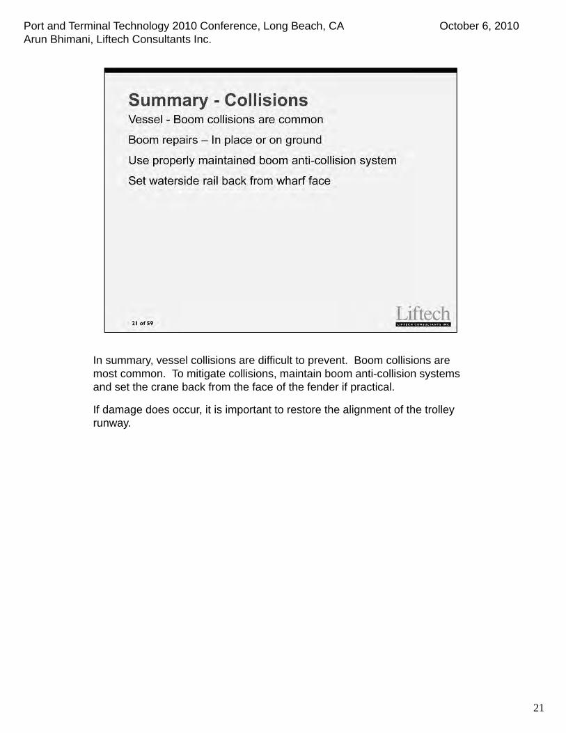
In summary, vessel collisions are difficult to prevent. Boom collisions are most common. To mitigate collisions, maintain boom anti-collision systems and set the crane back from the face of the fender if practical.
If damage does occur, it is important to restore the alignment of the trolley runway.
21
Port and Terminal Technology 2010 Conference, Long Beach, CA October 6, 2010Arun Bhimani, Liftech Consultants Inc.
22
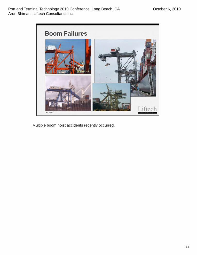
Multiple boom hoist accidents recently occurred.
Port and Terminal Technology 2010 Conference, Long Beach, CA October 6, 2010Arun Bhimani, Liftech Consultants Inc.
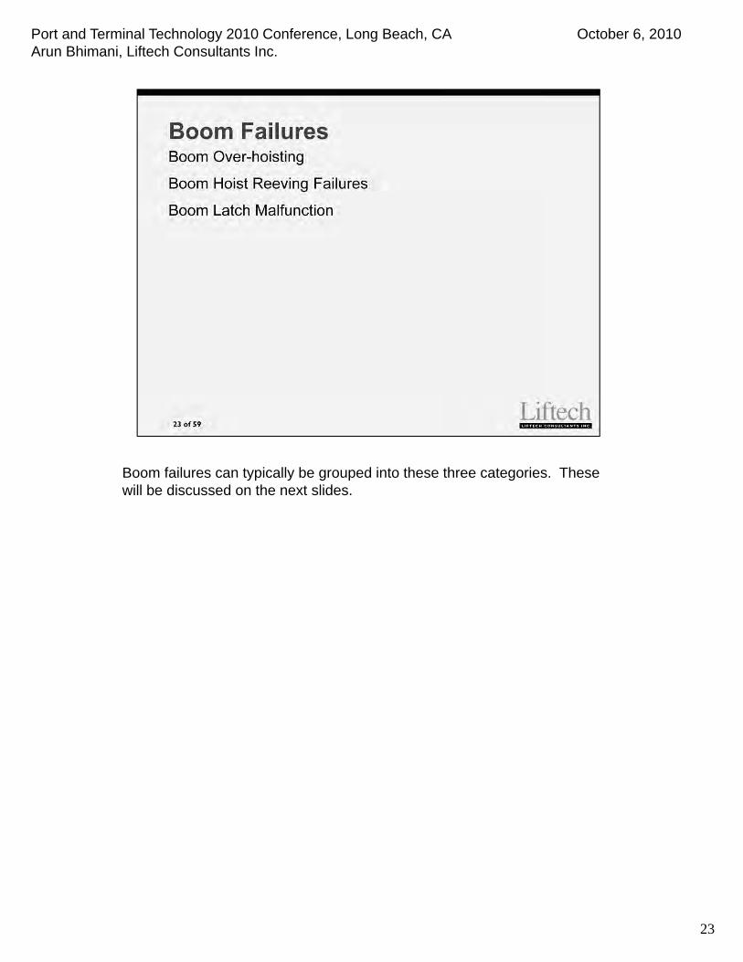
Boom failures can typically be grouped into these three categories. These will be discussed on the next slides.
23
Port and Terminal Technology 2010 Conference, Long Beach, CA October 6, 2010Arun Bhimani, Liftech Consultants Inc.
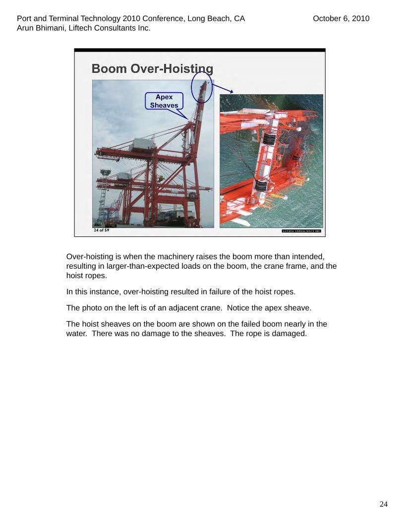
Over-hoisting is when the machinery raises the boom more than intended, resulting in larger-than-expected loads on the boom, the crane frame, and the hoist ropes.
In this instance, over-hoisting resulted in failure of the hoist ropes.
The photo on the left is of an adjacent crane. Notice the apex sheave.
The hoist sheaves on the boom are shown on the failed boom nearly in the water. There was no damage to the sheaves. The rope is damaged.
24

Port and Terminal Technology 2010 Conference, Long Beach, CA October 6, 2010Arun Bhimani, Liftech Consultants Inc.
Boom hoist system failures have occurred for a variety of reasons. Some include latch malfunctions, ropes jumping sheaves, damage to the rope, and inadequate rope attachments.
25

Port and Terminal Technology 2010 Conference, Long Beach, CA October 6, 2010Arun Bhimani, Liftech Consultants Inc.
On the failed crane, the rope on the side of the reeving failed. The exact cause of the rope failure is unknown. The rope may have jumped the sheave.The stop clamp did not hold the rope after the rope broke. The clamp was probably installed improperly.
26

Port and Terminal Technology 2010 Conference, Long Beach, CA October 6, 2010Arun Bhimani, Liftech Consultants Inc.
To help prevent hoist failures, we suggest stowing the boom on the ropes. If stowing at the apex, use pins instead of latches. Provide limit switches for boom location and for slack rope conditions. Raise and lower booms from the operating station on the waterside trolley girder support beam.
27
Port and Terminal Technology 2010 Conference, Long Beach, CA October 6, 2010Arun Bhimani, Liftech Consultants Inc.
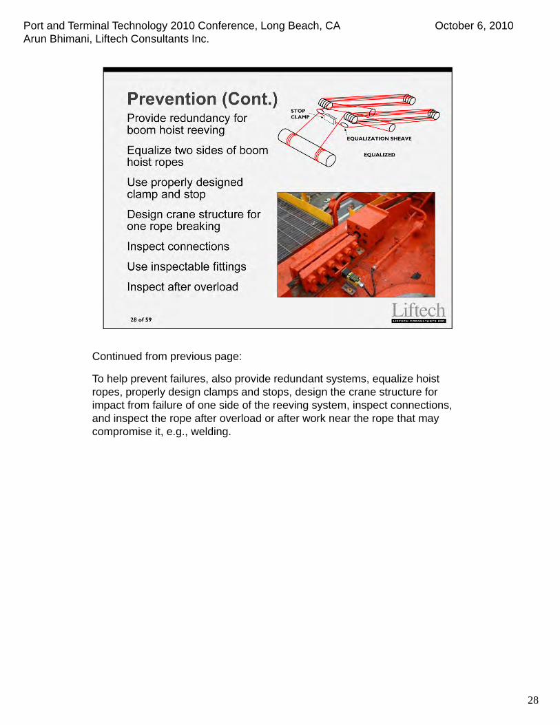
Continued from previous page:
To help prevent failures, also provide redundant systems, equalize hoist ropes, properly design clamps and stops, design the crane structure for impact from failure of one side of the reeving system, inspect connections, and inspect the rope after overload or after work near the rope that may compromise it, e.g., welding.
28

Port and Terminal Technology 2010 Conference, Long Beach, CA October 6, 2010Arun Bhimani, Liftech Consultants Inc.
29
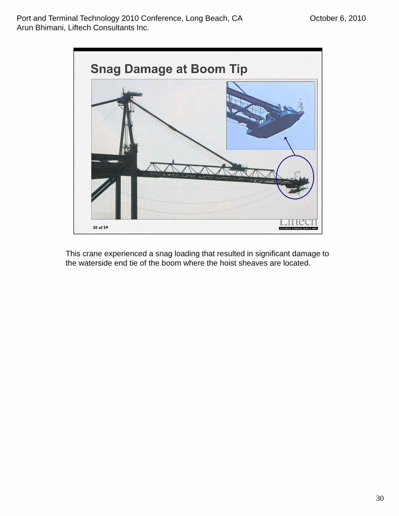
Snag accidents are common and can result in a severe loading.
Port and Terminal Technology 2010 Conference, Long Beach, CA October 6, 2010Arun Bhimani, Liftech Consultants Inc.
This crane experienced a snag loading that resulted in significant damage to the waterside end tie of the boom where the hoist sheaves are located.
30

Port and Terminal Technology 2010 Conference, Long Beach, CA October 6, 2010Arun Bhimani, Liftech Consultants Inc.
Damage to the end tie is shown here. The sheave brackets did not pull from the boom structure, but pulled the boom structure up.
The damage was caused by the severe loading and significant corrosion of the end tie structure.
31
Port and Terminal Technology 2010 Conference, Long Beach, CA October 6, 2010Arun Bhimani, Liftech Consultants Inc.
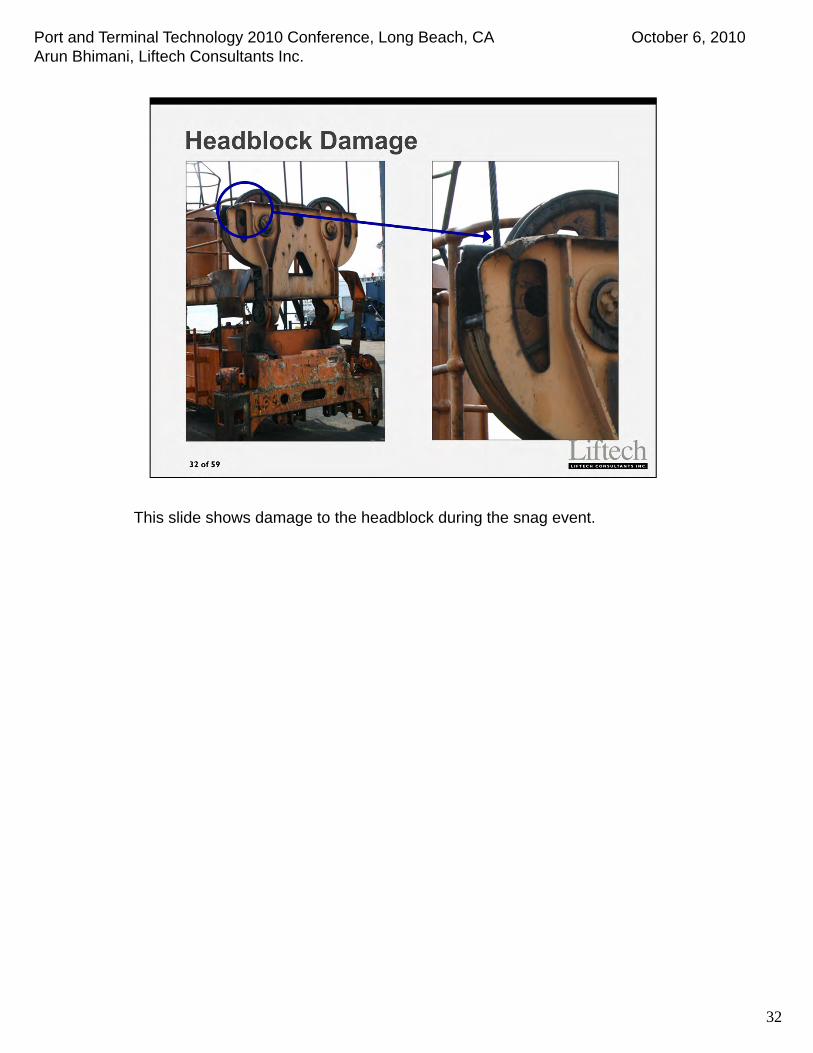
This slide shows damage to the headblock during the snag event.
32

Port and Terminal Technology 2010 Conference, Long Beach, CA October 6, 2010Arun Bhimani, Liftech Consultants Inc.
3333
To help prevent snag accidents, cranes typically have snag control systems.
It is common for recent cranes to have the Anti-Snag and T/L/S systems combined at the TG end tie beam.
Port and Terminal Technology 2010 Conference, Long Beach, CA October 6, 2010Arun Bhimani, Liftech Consultants Inc.
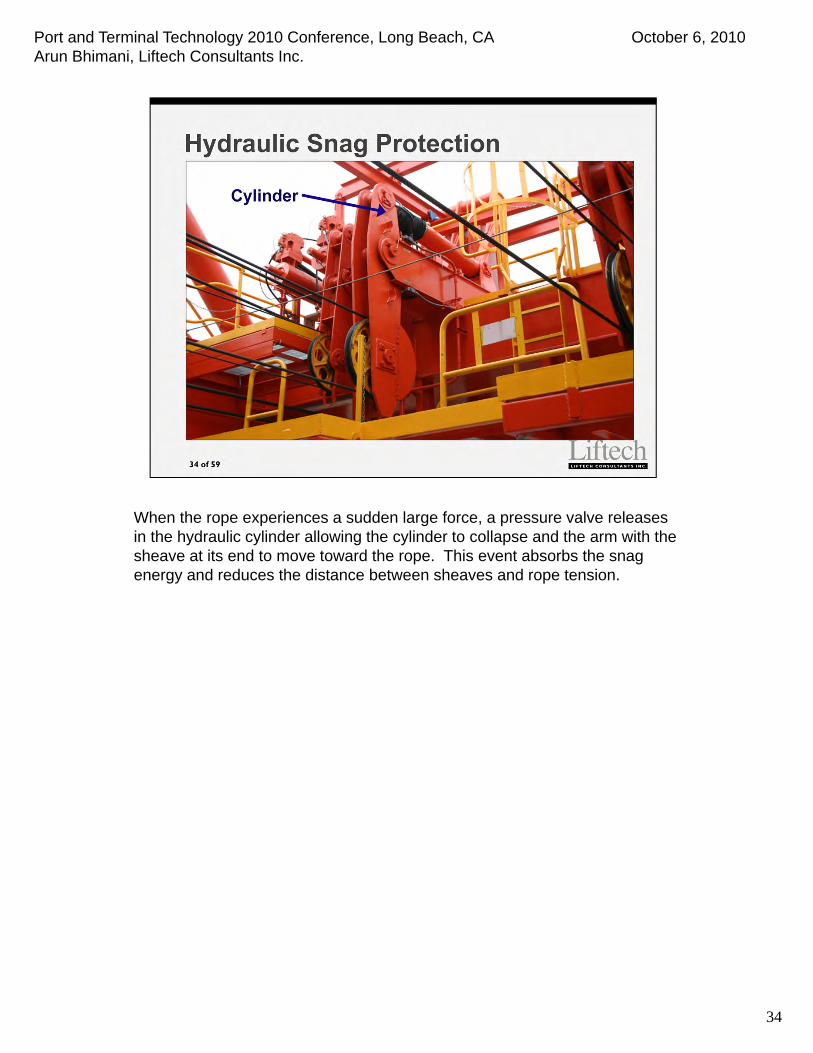
When the rope experiences a sudden large force, a pressure valve releases in the hydraulic cylinder allowing the cylinder to collapse and the arm with the sheave at its end to move toward the rope. This event absorbs the snag energy and reduces the distance between sheaves and rope tension.
34
Port and Terminal Technology 2010 Conference, Long Beach, CA October 6, 2010Arun Bhimani, Liftech Consultants Inc.
35
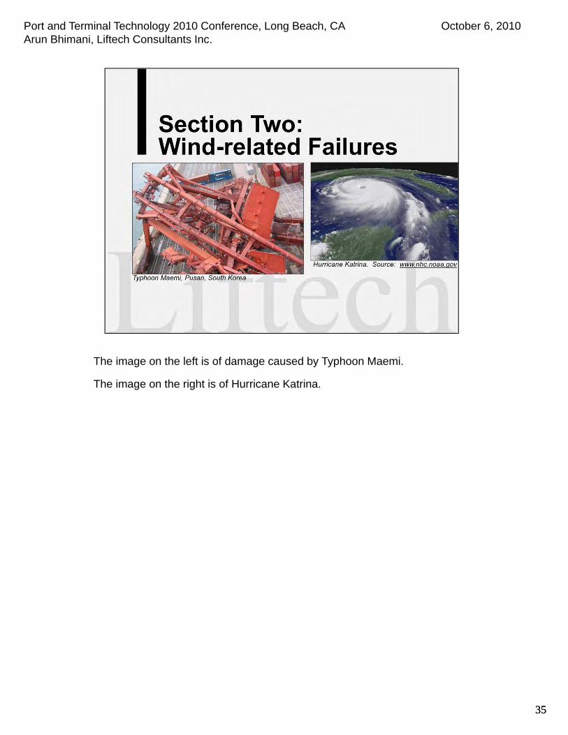
The image on the left is of damage caused by Typhoon Maemi.
The image on the right is of Hurricane Katrina.
35
Port and Terminal Technology 2010 Conference, Long Beach, CA October 6, 2010Arun Bhimani, Liftech Consultants Inc.
36
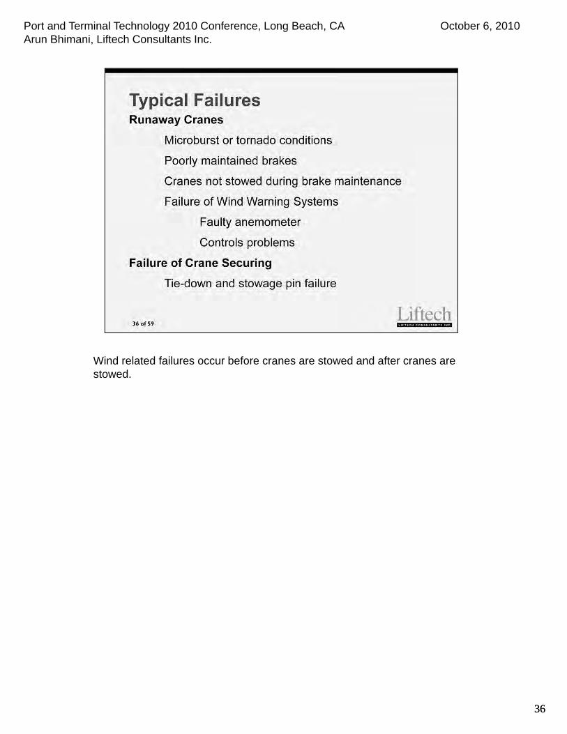
Wind related failures occur before cranes are stowed and after cranes are stowed.
36
Port and Terminal Technology 2010 Conference, Long Beach, CA October 6, 2010Arun Bhimani, Liftech Consultants Inc.
37
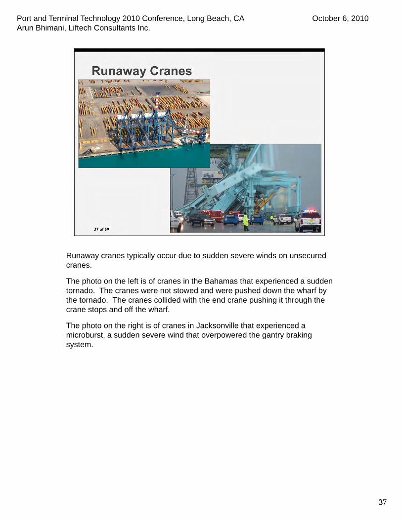
Runaway cranes typically occur due to sudden severe winds on unsecured cranes.
The photo on the left is of cranes in the Bahamas that experienced a sudden tornado. The cranes were not stowed and were pushed down the wharf by the tornado. The cranes collided with the end crane pushing it through the crane stops and off the wharf.
The photo on the right is of cranes in Jacksonville that experienced a microburst, a sudden severe wind that overpowered the gantry braking system.
37

Port and Terminal Technology 2010 Conference, Long Beach, CA October 6, 2010Arun Bhimani, Liftech Consultants Inc.
38
The crane braking system typically consists of the gantry motor resistance and their brakes. The gantry motor braking is augmented by other braking systems such as rail brakes or caliper brakes, but usually not both.
Stowage pins are provided for securing the crane and are usually needed as the braking system capacity is not adequate for the severe design wind.
Some operational considerations include providing ample time to stow the crane and realizing that the brake capacity of a moving wheel is less than that of a stopped wheel.
The static coefficient of friction is often significantly larger than the dynamic coefficient of friction. A moving crane also has significant inertia.
38

Port and Terminal Technology 2010 Conference, Long Beach, CA October 6, 2010Arun Bhimani, Liftech Consultants Inc.
39
These photographs show six collapsed cranes due to Typhoon Maemi in Pusan, South Korea. The two photographs are taken from each end of the wharf.
Tie-downs failed. After failing, progressive failures ensued as cranes collided with each other.
39

Port and Terminal Technology 2010 Conference, Long Beach, CA October 6, 2010Arun Bhimani, Liftech Consultants Inc.
40
To explain why failures occur, I will discuss the stowage components of a crane in a high wind area.
Stowage pins resist lateral loading. Tie-downs resist the uplift due to the overturning moment.
40

Port and Terminal Technology 2010 Conference, Long Beach, CA October 6, 2010Arun Bhimani, Liftech Consultants Inc.
41
Failures have never initiated in the crane structure.
Failures have always initiated in the wharf stowage hardware.
The reasons for these failures can be equally attributed to incorrect calculations, poor design, and poor fabrication.
41

Port and Terminal Technology 2010 Conference, Long Beach, CA October 6, 2010Arun Bhimani, Liftech Consultants Inc.
42
There were multiple types of failures during Typhoon Maemi. Tie-down anchorage was one failure type. Smooth anchors pulled out of the wharf.
Design = headed anchorage
Fabricated = no head
42
Port and Terminal Technology 2010 Conference, Long Beach, CA October 6, 2010Arun Bhimani, Liftech Consultants Inc.
43
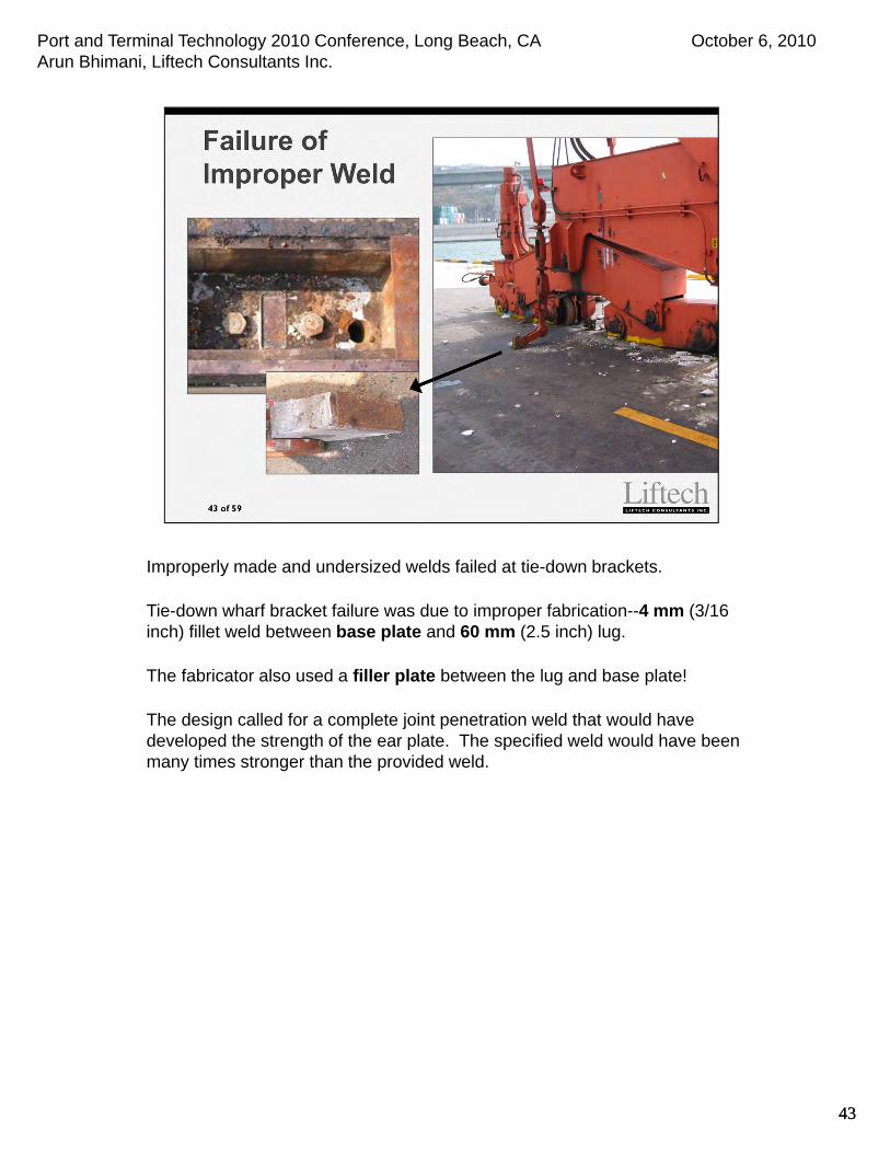
Improperly made and undersized welds failed at tie-down brackets.
Tie-down wharf bracket failure was due to improper fabrication--4 mm (3/16 inch) fillet weld between base plate and 60 mm (2.5 inch) lug.
The fabricator also used a filler plate between the lug and base plate!
The design called for a complete joint penetration weld that would have developed the strength of the ear plate. The specified weld would have been many times stronger than the provided weld.
43

Port and Terminal Technology 2010 Conference, Long Beach, CA October 6, 2010Arun Bhimani, Liftech Consultants Inc.
44
Local concrete bearing failures occurred at stowage sockets. The design did not consider the large bearing stresses that occur. This was exacerbated due to crane uplift and localized bearing of the stow pin on the upper end of the cast-in-place tube.
44

Port and Terminal Technology 2010 Conference, Long Beach, CA October 6, 2010Arun Bhimani, Liftech Consultants Inc.
45
When calculating the design forces, the deflection of the crane must be considered, particularly when there are multiple tie-downs at a corner.
On some cranes we have studied we determined that one tie-down at a corner may experience 100% of its design load before the other corner tie-down experiences any loading.
Following are some causes of uneven tie-down loads:
Crane structure deforms, translating and rotating
Gantry wheels can shift
Gap in stowage pin socket allows gantry wheels to roll (or slide) along the rail
Links are not perfectly straight
Wharf pins are not symmetric
45

Port and Terminal Technology 2010 Conference, Long Beach, CA October 6, 2010Arun Bhimani, Liftech Consultants Inc.
46
To avoid uneven tie-down loads, if practical use one tie-down per corner or locate all tie-downs on one side of the sill beam, otherwise equalize.
As mentioned, the best method is to use a single tie-down per corner, but this is often impractical due to the size and weight of the tie-down system components, e.g., the weight of the wharf link plate.
The mechanical equalizer beam system is not presented as it is heavy and difficult to implement.
Another choice is to use a ductile link.
46
Port and Terminal Technology 2010 Conference, Long Beach, CA October 6, 2010Arun Bhimani, Liftech Consultants Inc.
47
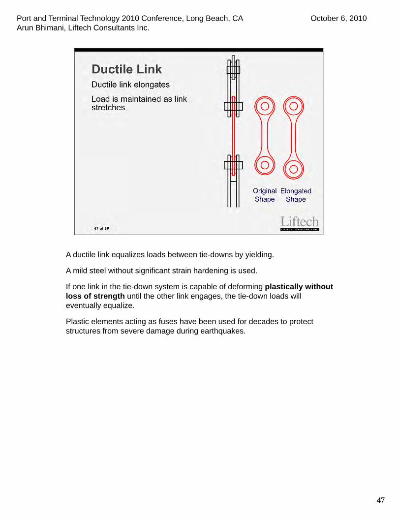
A ductile link equalizes loads between tie-downs by yielding.
A mild steel without significant strain hardening is used.
If one link in the tie-down system is capable of deforming plastically without loss of strength until the other link engages, the tie-down loads will eventually equalize.
Plastic elements acting as fuses have been used for decades to protect structures from severe damage during earthquakes.
47
Port and Terminal Technology 2010 Conference, Long Beach, CA October 6, 2010Arun Bhimani, Liftech Consultants Inc.
48
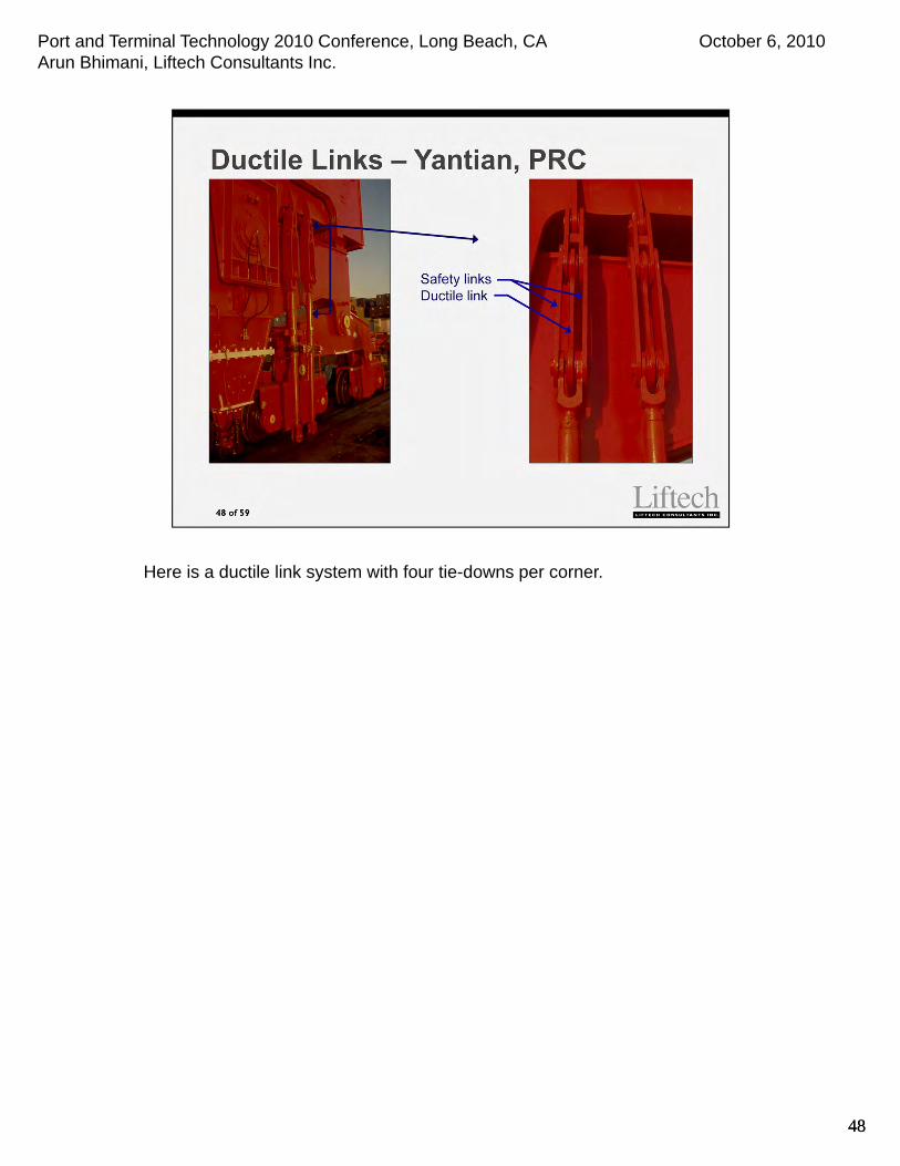
Here is a ductile link system with four tie-downs per corner.
48

Port and Terminal Technology 2010 Conference, Long Beach, CA October 6, 2010Arun Bhimani, Liftech Consultants Inc.
4949
In summary:
1. Reliable wind warning systems, brake maintenance, and stowage procedures can help reduce the risk of runaway cranes due to severe winds that develop with little warning.
2. Consider the crane deformation when designing stowage hardware.
3. Stowage hardware is inexpensive; design conservatively.
4. Monitor fabrication and installation!
5. The probability of severe winds is increasing.
Port and Terminal Technology 2010 Conference, Long Beach, CA October 6, 2010Arun Bhimani, Liftech Consultants Inc.
50

Port and Terminal Technology 2010 Conference, Long Beach, CA October 6, 2010Arun Bhimani, Liftech Consultants Inc.
51
Cranes are typically transported by barge or ship. Barges are typically used in the US due to the Jones Act.
The design forces for transport by barge are usually larger than for ships due to the dynamic response of the barge and because towed barges are usually slower than ships and are less likely to avoid severe weather.

Port and Terminal Technology 2010 Conference, Long Beach, CA October 6, 2010Arun Bhimani, Liftech Consultants Inc.
52
This is a photo of a barge deck after two cranes fell overboard. We do not know the circumstances of the accident, but notice that the braces are not aligned with the internal structure of the barge.
Port and Terminal Technology 2010 Conference, Long Beach, CA October 6, 2010Arun Bhimani, Liftech Consultants Inc.
53
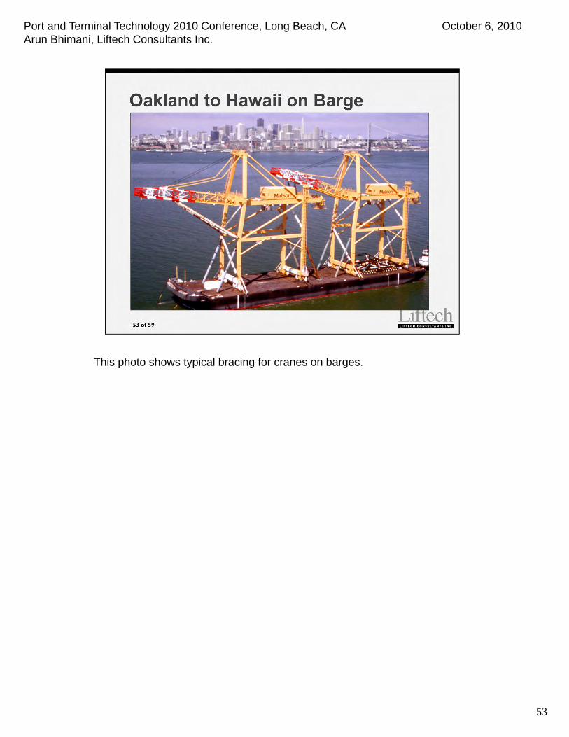
This photo shows typical bracing for cranes on barges.

Port and Terminal Technology 2010 Conference, Long Beach, CA October 6, 2010Arun Bhimani, Liftech Consultants Inc.
54
Transport by heavy lift vessels is more common than by barge, particularly for the delivery of new cranes.

Port and Terminal Technology 2010 Conference, Long Beach, CA October 6, 2010Arun Bhimani, Liftech Consultants Inc.
55
Damage to cranes transported by vessels also happens.
In this accident, the bracing connecting the crane to the vessel held; however, the bracing within the crane structure itself did not. It is important to perform an appropriate finite element analysis to correctly estimate the design forces within the crane structure and added bracing.

Port and Terminal Technology 2010 Conference, Long Beach, CA October 6, 2010Arun Bhimani, Liftech Consultants Inc.
56
Estimate voyage forces correctly considering the conditions and an appropriate criteria. Do not relax accepted design criteria regardless of how mild the weather is expected to be. Unexpected weather commonly occurs.
Accurately calculate the forces and stresses in the bracing and crane structure. This usually requires analysis using a finite element program and considering the crane structure and bracing together.
Be sure to review the entire load path from the crane structure down into the structure of the vessel. The load does not stop at the deck of the vessel!

Port and Terminal Technology 2010 Conference, Long Beach, CA October 6, 2010Arun Bhimani, Liftech Consultants Inc.
57
Many things can go wrong.
Just prior to delivery, the ship’s captain decided to begin moving the crane without installing the “hold back” lines.
The ship pitched and the crane rolled off the ship.

Port and Terminal Technology 2010 Conference, Long Beach, CA October 6, 2010Arun Bhimani, Liftech Consultants Inc.
5858

Port and Terminal Technology 2010 Conference, Long Beach, CA October 6, 2010Arun Bhimani, Liftech Consultants Inc.
5959