lifting operations - our expectations - balfourbeatty.com rope drums ... * in-line load is applied...
TRANSCRIPT
Lifting Operations - Our Expectations Reference Material: HSF-RM-0039a
Contents
1.0 Introduction ............................................................................................................................................ 4
2.0 Planning the Lift ..................................................................................................................................... 4
3.0 Planning Deliveries ................................................................................................................................ 5
4.0 Eye Bolts ................................................................................................................................................ 5
4.1 Selection ............................................................................................................................................ 5
4.2 Safe and Correct Use ........................................................................................................................ 5
5.0 Hoist Rings ............................................................................................................................................. 6
6.0 Shackles ................................................................................................................................................ 6
6.1 Selection ............................................................................................................................................ 6
6.2 Side Loadings .................................................................................................................................... 6
6.3 Examples ........................................................................................................................................... 7
7.0 Hooks ..................................................................................................................................................... 8
7.1 Attaching/Detaching and Securing Loads ......................................................................................... 8
7.2 Congested Hooks .............................................................................................................................. 8
7.3 Latch Hooks ....................................................................................................................................... 8
8.0 Selecting the Right Slings ...................................................................................................................... 9
8.1 Chain Slings –using the Uniform method of rating .......................................................................... 13
8.2 Choke Hitch ..................................................................................................................................... 13
8.3 Chain Slings - Trigonometric ........................................................................................................... 14
8.4 Methods of Slinging ......................................................................................................................... 15
8.5 Methods of Use ................................................................................................................................ 15
8.6 Safe Use of Slings ........................................................................................................................... 16
9.0 Colour Coding of Lifting Accessories ................................................................................................... 17
9.1 Examination ..................................................................................................................................... 17
10.0 Sling Storage ....................................................................................................................................... 18
11.0 Misuse of Slings ................................................................................................................................... 18
12.0 Lifting Accessories – Typical Faults..................................................................................................... 19
13.0 Inspection and Maintenance ................................................................................................................ 20
Document Authoriser: Craig McCallum Uncontrolled when printed or downloaded Date of Issue: 02/05/2018 Page 1 of 69 Version: 1.1 A Balfour Beatty UK Document

Lifting Operations - Our Expectations Reference Material: HSF-RM-0039a
13.1 Slings ............................................................................................................................................... 20
13.2 Chain Slings ..................................................................................................................................... 20
13.3 Textile Slings .................................................................................................................................... 20
13.4 Single Trip Slings ............................................................................................................................. 21
14.0 Securing Loads for Transport .............................................................................................................. 22
15.0 Securing of loads ................................................................................................................................. 22
15.1 Security of Loads Even if the Load Clashes with a Structure and Tilts ........................................... 22
16.0 Lifting by Telescopic Handler ............................................................................................................... 23
17.0 Lifting with Excavator ........................................................................................................................... 24
18.0 Lifting with Chain Slings – Incorrect Slinging Techniques ................................................................... 25
19.0 Loose Material on Loads ..................................................................................................................... 26
20.0 Stillages ............................................................................................................................................... 26
21.0 Muck/Concrete/Tip Skips ..................................................................................................................... 27
22.0 Palletised Material................................................................................................................................ 28
23.0 Lifting Points ........................................................................................................................................ 28
24.0 Pipe and Hose Lifting ........................................................................................................................... 30
25.0 Rope Drums ......................................................................................................................................... 32
26.0 Plunge Columns ................................................................................................................................... 33
27.0 Kelly Bars ............................................................................................................................................. 34
28.0 Pile Casings ......................................................................................................................................... 35
29.0 Pile Cages ............................................................................................................................................ 36
30.0 Augers .................................................................................................................................................. 37
31.0 Digging and Cleaning Buckets ............................................................................................................. 38
32.0 Core Barrels ......................................................................................................................................... 39
33.0 Vibro Flots ............................................................................................................................................ 40
34.0 Wood Bundles ...................................................................................................................................... 41
35.0 Column Shutter .................................................................................................................................... 42
36.0 Wall Shutter ......................................................................................................................................... 42
37.0 Prefab Re Bar Cages ........................................................................................................................... 43
38.0 Moveable Scaffolding .......................................................................................................................... 43
Document Authoriser: Craig McCallum Uncontrolled when printed or downloaded Date of Issue: 02/05/2018 Page 2 of 69 Version: 1.1 A Balfour Beatty UK Document
Lifting Operations - Our Expectations Reference Material: HSF-RM-0039a
39.0 Plasterboard ......................................................................................................................................... 43
40.0 Various Construction Materials and Tools ........................................................................................... 44
41.0 Pods/Pipework/Ventilation/Air Conditioning Units ............................................................................... 45
42.0 Metal Decking/Pre-formed Metal Panels ............................................................................................. 45
43.0 Windows/Stillages of Concrete Panels/Glass Frames ........................................................................ 46
44.0 ACRO Props and Loose Material ........................................................................................................ 47
45.0 Structural Steel .................................................................................................................................... 48
46.0 Bulk Bag and Slabs.............................................................................................................................. 49
47.0 Concrete Agitators ............................................................................................................................... 50
48.0 Precast Piles ........................................................................................................................................ 51
49.0 Tremie Pipes ........................................................................................................................................ 52
50.0 Recommended Hand Signals .............................................................................................................. 66
51.0 Using Two Way Radio ......................................................................................................................... 68
Document Authoriser: Craig McCallum Uncontrolled when printed or downloaded Date of Issue: 02/05/2018 Page 3 of 69 Version: 1.1 A Balfour Beatty UK Document
Lifting Operations - Our Expectations Reference Material: HSF-RM-0039a
Introduction
The following guide was developed to eliminate, minimise and mitigate fatal risks and hazards, keeping the public safe from harm and maintaining Zero harm day to day.
This guide covers Lifting, Slinging and Signalling Operations on Balfour Beatty UK projects, factories and depots.
The information good practice and legislative requirements contained should be shared and adopted throughout to improve efficiency and safety on site
This Guide should help form the standard slinging and signalling arrangements in your schedule of common lifts within the lift plan.
All chains, ropes or items of lifting accessories used in raising, lowering or as a means of suspension will be of adequate strength, sound condition, correctly marked, fit for purpose and capable of securing the load. The principle is therefore to achieve a Zero Harm Lift
Planning the Lift
Planning the lifting operation is essential to ensure that the lift is carried out safely and efficiently but all operatives and supervisors must ensure that lifts are carried out in accordance with the site specific Lift Plan. The following points must always be considered and addressed in the Lift Plan.
• Access to the lifting points on the load
• Where the load is to be picked up from
• What areas are to be passed over
• Proximity to the public
• Competence in the correct use of the lifting accessory
• Any obstructions or potential clashes with tall plant or equipment
• Where the load is to be placed
• Establishment of Exclusion Zones
• Selection of the correct lifting accessory (materials and SWL)
• How the load is to be slung and secured
• How the slings are to be removed and access to them
• How the machine operator will be directed
• The weight and centre of gravity of the load
• Clear consistent communication between all parties
• The weather
• Trial lift must be undertaken for every lift to check balance, stability and loose material
• Slinger Signaller must be easily identifiable from a distance
Document Authoriser: Craig McCallum Uncontrolled when printed or downloaded Date of Issue: 02/05/2018 Page 4 of 69 Version: 1.1 A Balfour Beatty UK Document

Lifting Operations - Our Expectations Reference Material: HSF-RM-0039a
Planning Deliveries
All deliveries must be unloaded safely:
• Ensure you made the appropriate Plans
• Is there a competent person (Plant and Vehicle Marshal) present to guide the vehicles and supervise the vehicle set up/unloading operations on site?
• Where access is unavoidable on the rear of a vehicle has fall protection procedure been developed, available and supervised?
• Are the deliveries scheduled to the appropriate times? ‘Just In time Deliveries’
• Is there sufficient space to load/unload safely? Can lifting equipment such as cranes, Hiabs or fork lifts manoeuvre into position?
Eye Bolts
Selection
The main considerations when selecting eye bolts are:
• The weight of the load being lifted
• The number of eye bolts sharing the load
• Whether or not an inclined loading will be effected
• Centre of gravity of the load
• Securing eye bolt
Vertical Inclined
Loading Loading
WARNING
Dynamo eye bolts are only suitable for an axial (vertical) lift and any angular pull whatsoever will bend the screwed shank and lead to failure. These are considered unsuitable and their use is not recommended.
Safe and Correct Use
Eye bolts should always be loaded in the same plane
as the eye and NEVER against the plane of the eye.
Correct Incorrect 5° Maximum
Deviation
Document Authoriser: Craig McCallum Uncontrolled when printed or downloaded Date of Issue: 02/05/2018 Page 5 of 69 Version: 1.1 A Balfour Beatty UK Document

Lifting Operations - Our Expectations Reference Material: HSF-RM-0039a
360° Swivel No deration for angular loadings
Incorrect
When lifting with a pair of eye bolts ALWAYS use a 2
leg sling. NEVER use a sling in a basket format, as this
can drastically overload the eyebolts.
Two-Leg Sling Basket Format
Hoist Rings
The 2 advantages of hoist rings are that:
• They will swivel to the correct orientation ie no requirement for packing with shim washers.
• They pivot to suit the sling angle between 0° and 90° and do NOT required to be derated.
Check that the thread on the load is compatible with the thread on the bolt.
Shackles
Selection
Shackles should be selected to suit the load being lifted allowing for any increased loadings due to sling angles. The dimensions of the shackle will often be governed by the hole diameter and the thickness of the material of the lifting eye. The selection between Bow type and D type will depend on the number of components being connected.
Side Loadings
Side Loading Reduction Chart For Screw Pin and Bolt Type Shackles Only †
Angle of Side Load from Vertical In-line of Shackle
Adjusted Working Load Limit
Angle Loads must be applied in the plane of the bow.
0 ° In-Line * 100% of Rated Working Load Limit
45 ° from In-Line * 70% of Rated Working Load Limit
90 °from In-Line * 50% of Rated Working Load Limit
* In-Line load is applied perpendicular to pin † DO NOT SIDE LOAD ROUND PIN SHACKLES
180° Pivot
Two Components
Crown Bearing Point
Pin Bearing Point
Three or more Components
Pin Bearing Point
Crown Bearing Points
In-line
90°
45°
Document Authoriser: Craig McCallum Uncontrolled when printed or downloaded Date of Issue: 02/05/2018 Page 6 of 69 Version: 1.1 A Balfour Beatty UK Document

Lifting Operations - Our Expectations Reference Material: HSF-RM-0039a
Examples
Poor Practice Good Practice Incorrect: if the load shifts the sling will unscrew the shackle pin.
Incorrect: Shackle pin bearing on running line can work loose.
Never replace the shackle pin with an ordinary bolt as it will not be as strong at the proper pin which is manufactured from a high grade material. The load will bend or shear the bolt
Always centre the load on the shackle pin to avoid angular pulls against the leg of the shackle.
Avoid using the shackle in such a manner that movement of the load rope could unscrew the shackle pin.
On assembly shackle pin should always be screwed tight – DO NOT screw back to allow for easier removal.
Avoid congesting hooks with more than one sling. When attaching two or more wire rope slings to the hook block, these must always be attached via a master ring. If it is not possible to use a master ring, a hook block with mechanical lock must be used
Document Authoriser: Craig McCallum Uncontrolled when printed or downloaded Date of Issue: 02/05/2018 Page 7 of 69 Version: 1.1 A Balfour Beatty UK Document
Lifting Operations - Our Expectations Reference Material: HSF-RM-0039a
Hooks
Attaching/Detaching and Securing Loads
You should ensure that any lifting accessories used for securing the load are compatible with the load, taking into account any attachment points on the load, the environmental conditions in which the accessories will be used and their configuration of use. Lifting accessories should be selected as a function of the load to be handled, gripping points, attachment tackle and the atmospheric conditions having regard to the mode and configuration of slinging.
Congested Hooks
Only one lifting sling is permitted within the hook block. The use of a large bow shackle will assist. This will avoid the risk of the second slings being accidentally displaced from the hook.
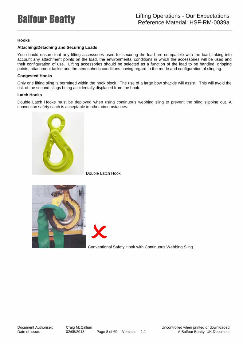
Latch Hooks
Double Latch Hooks must be deployed when using continuous webbing sling to prevent the sling slipping out. A convention safety catch is acceptable in other circumstances.
Double Latch Hook
Conventional Safety Hook with Continuous Webbing Sling
Document Authoriser: Craig McCallum Uncontrolled when printed or downloaded Date of Issue: 02/05/2018 Page 8 of 69 Version: 1.1 A Balfour Beatty UK Document
Lifting Operations - Our Expectations Reference Material: HSF-RM-0039a
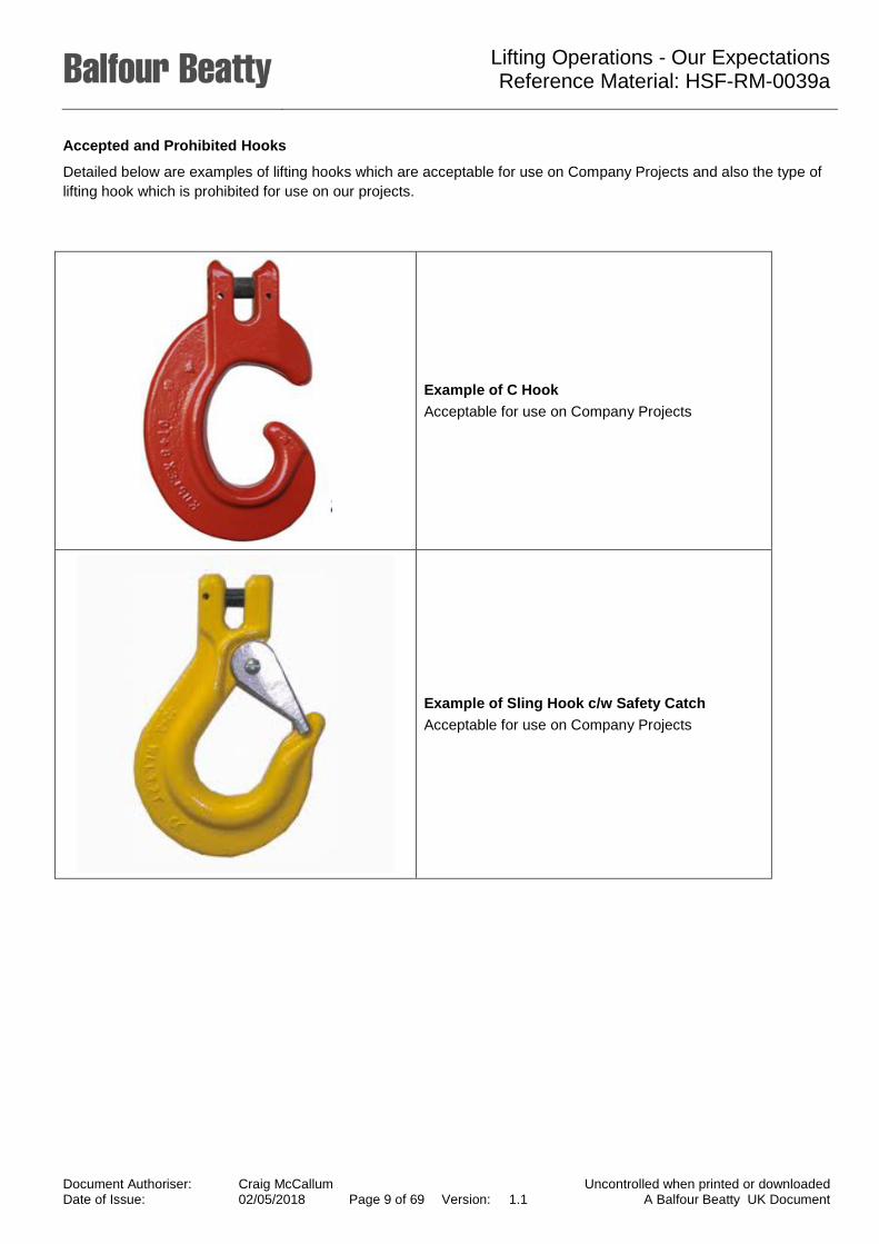
Accepted and Prohibited Hooks
Detailed below are examples of lifting hooks which are acceptable for use on Company Projects and also the type of lifting hook which is prohibited for use on our projects.
Example of C Hook Acceptable for use on Company Projects
Example of Sling Hook c/w Safety Catch Acceptable for use on Company Projects
Document Authoriser: Craig McCallum Uncontrolled when printed or downloaded Date of Issue: 02/05/2018 Page 9 of 69 Version: 1.1 A Balfour Beatty UK Document

Lifting Operations - Our Expectations Reference Material: HSF-RM-0039a
Example of Double Latch Hook Recommended for use on Company Projects
Open Sling Hooks (without safety catches) PROHIBITED for use on Company Projects
Example Swivel hook with castellated nut Swivel hooks with castellated nuts must not be used for lifting which involves continual turning of the load, as this hook is designed as a positioning device only and is not designed to rotate under load. Bearing type hooks must be used instead.
Document Authoriser: Craig McCallum Uncontrolled when printed or downloaded Date of Issue: 02/05/2018 Page 10 of
69 Version: 1.1 A Balfour Beatty UK Document

Lifting Operations - Our Expectations Reference Material: HSF-RM-0039a
Selecting the Right Slings
When selecting the safe working load of slings a number of factors will reduce the sling’s capabilities and therefore they need to be de-rated.
Working Load Limits according to the standard (Uniform Load) method of rating.
If chain slings are to be used in more demanding conditions (e.g. high temperature, asymmetric load distribution, edge load, impact/shock loads) the maximum load capacity values must be reduced by the load factors.
Where slings and other lifting equipment are used more than 8 hours per day over a 40 hour week, consider reducing frequency of thorough examination from 6 monthly to 3 monthly.
Load Cells - where unable to calculate an accurate weight of the load or when tandem lifting, strongly consider the use of a load cell to monitor the loading being applied to each crane during the lift.
Note: when slings are used in choke hitch the Working Load Limit should be reduced by 20%.
Note: How the lifting angles increase tension in multi leg slings and also the lateral forces in the shackles, lifting eyes and load itself.
Check that the lifting points and the load are designed for an angled lift.
Note: avoid, where possible, using single leg slings in a multiple application. When using single leg slings in pairs, the greater the angle, the increased load on the slings.
Horizontal Force Horizontal Force
Loading in sling leg
Variation of sling leg loading with leg angle for a load of 1t
0.7t
β = 45°
0.7t
60°
75°
80°
1t 1t
2t 2t
3t 3t
1 tonne
Document Authoriser: Craig McCallum Uncontrolled when printed or downloaded Date of Issue: 02/05/2018 Page 11 of
69 Version: 1.1 A Balfour Beatty UK Document
Lifting Operations - Our Expectations Reference Material: HSF-RM-0039a
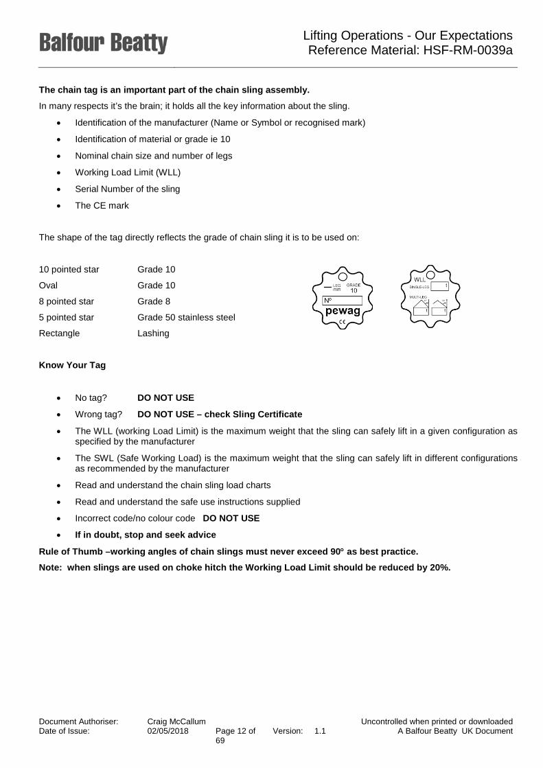
The chain tag is an important part of the chain sling assembly.
In many respects it’s the brain; it holds all the key information about the sling.
• Identification of the manufacturer (Name or Symbol or recognised mark)
• Identification of material or grade ie 10
• Nominal chain size and number of legs
• Working Load Limit (WLL)
• Serial Number of the sling
• The CE mark
The shape of the tag directly reflects the grade of chain sling it is to be used on:
10 pointed star Grade 10
Oval Grade 10
8 pointed star Grade 8
5 pointed star Grade 50 stainless steel
Rectangle Lashing
Know Your Tag
• No tag? DO NOT USE
• Wrong tag? DO NOT USE – check Sling Certificate
• The WLL (working Load Limit) is the maximum weight that the sling can safely lift in a given configuration as specified by the manufacturer
• The SWL (Safe Working Load) is the maximum weight that the sling can safely lift in different configurations as recommended by the manufacturer
• Read and understand the chain sling load charts
• Read and understand the safe use instructions supplied
• Incorrect code/no colour code DO NOT USE
• If in doubt, stop and seek advice
Rule of Thumb –working angles of chain slings must never exceed 90° as best practice.
Note: when slings are used on choke hitch the Working Load Limit should be reduced by 20%.
Document Authoriser: Craig McCallum Uncontrolled when printed or downloaded Date of Issue: 02/05/2018 Page 12 of
69 Version: 1.1 A Balfour Beatty UK Document

Lifting Operations - Our Expectations Reference Material: HSF-RM-0039a
Chain Slings –using the Uniform method of rating
Chain slings rated Working Load Limit (WLL) 0° - 90°or 90° - 120°
SAFE WORKING LOADS TONNES
GRADE 8 CHAIN – UNIFORM LOAD METHOD
Single Leg Slings Two Leg Slings Three Leg Slings Four Leg Slings
For Chain Size mm WLL Β = 0 - 45° β = 0 - 45° β = 0 - 45°
6 1.12 1.60 2.36 2.36
7 1.5 2.12 3.15 3.15
8 2.0 2.8 4.25 4.25
10 3.15 4.25 6.7 6.7
13 5.3 7.5 11.2 11.2
16 8.0 11.2 17.0 17.0
19 11.2 16.0 23.6 23.6
22 15.0 21.2 31.5 31.5
26 21.2 30.0 45.0 45.0
32 31.5 45.0 67.0 57.0
Note: Safety Factor 4:1. Above limits refer to normal use and equally loaded sling legs.
Rule of Thumb – working angles of chain slings must never exceed 90° as best practice.
Note: when Slings are used in choke hitch the Working Load Limit should be reduced by 20%
Choke Hitch
Do not ‘batter down’ slings to increase the grip, allow the angle to form naturally. Maximum permitted angle is 120°.
90°
Document Authoriser: Craig McCallum Uncontrolled when printed or downloaded Date of Issue: 02/05/2018 Page 13 of
69 Version: 1.1 A Balfour Beatty UK Document
Lifting Operations - Our Expectations Reference Material: HSF-RM-0039a
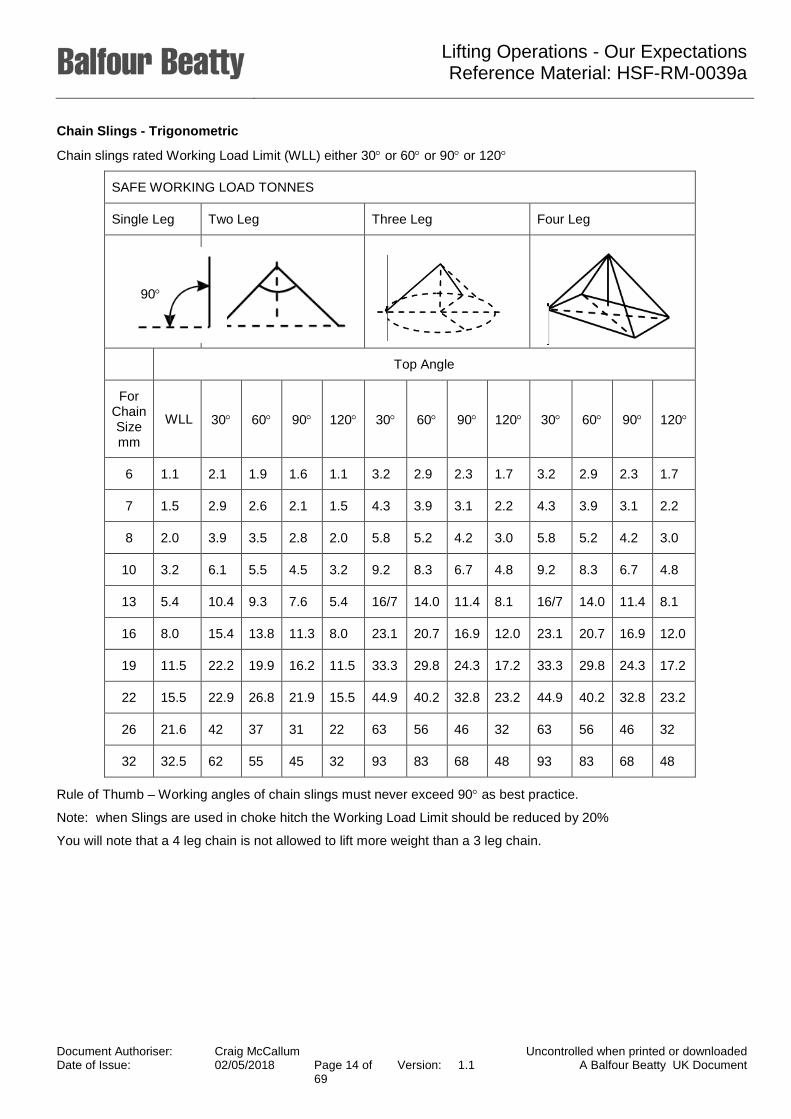
Chain Slings - Trigonometric
Chain slings rated Working Load Limit (WLL) either 30° or 60° or 90° or 120°
SAFE WORKING LOAD TONNES
Single Leg Two Leg Three Leg Four Leg
Top Angle
For Chain Size mm
WLL 30° 60° 90° 120° 30° 60° 90° 120° 30° 60° 90° 120°
6 1.1 2.1 1.9 1.6 1.1 3.2 2.9 2.3 1.7 3.2 2.9 2.3 1.7
7 1.5 2.9 2.6 2.1 1.5 4.3 3.9 3.1 2.2 4.3 3.9 3.1 2.2
8 2.0 3.9 3.5 2.8 2.0 5.8 5.2 4.2 3.0 5.8 5.2 4.2 3.0
10 3.2 6.1 5.5 4.5 3.2 9.2 8.3 6.7 4.8 9.2 8.3 6.7 4.8
13 5.4 10.4 9.3 7.6 5.4 16/7 14.0 11.4 8.1 16/7 14.0 11.4 8.1
16 8.0 15.4 13.8 11.3 8.0 23.1 20.7 16.9 12.0 23.1 20.7 16.9 12.0
19 11.5 22.2 19.9 16.2 11.5 33.3 29.8 24.3 17.2 33.3 29.8 24.3 17.2
22 15.5 22.9 26.8 21.9 15.5 44.9 40.2 32.8 23.2 44.9 40.2 32.8 23.2
26 21.6 42 37 31 22 63 56 46 32 63 56 46 32
32 32.5 62 55 45 32 93 83 68 48 93 83 68 48
Rule of Thumb – Working angles of chain slings must never exceed 90° as best practice.
Note: when Slings are used in choke hitch the Working Load Limit should be reduced by 20%
You will note that a 4 leg chain is not allowed to lift more weight than a 3 leg chain.
90°
Document Authoriser: Craig McCallum Uncontrolled when printed or downloaded Date of Issue: 02/05/2018 Page 14 of
69 Version: 1.1 A Balfour Beatty UK Document

Lifting Operations - Our Expectations Reference Material: HSF-RM-0039a
Methods of Slinging
SWL factors also apply according to the type of sling and how it is used.
Examples for various types of single-legged slings are shown here. The same principles also apply to multi-legged slings.
Single Leg In-line Single Leg Choked Single Leg Basket Single Leg Back Hocked
Single Leg Halshed Endless In-line Endless Choked Endless Basket
† Single wrapped
‡ Double wrapped
Methods of Use
The Safe working Load of the sling will change depending on how the sling has been attached. The table below gives guidance on the SWL for each method.
METHOD OF USE
Single Leg In-
line
Single Leg
Choked
Single Leg
Basket 0° - 90°
Single Leg Back Hooked
Single Leg
Halshed Endless In-Line
Endless Choked
Endless Basket 0° - 90°
SLI
NG
MAT
ER
IAL
Chain 1 0.8 1.4 1 1.5 N/A 1 N/A
Wire Rope 1 1 1.4 1 2 1 1 1.4
Webbing 1 0.8 1.4 N/A N/A 1 0.8 1.4
Fibre Rope 1 0.8 1.4 1 N/A 1 0.8 1.4
Round N/A N/A 1.4 N/A N/A 1 0.8 1.4
N/A = Not Applicable, DO NOT USE
Document Authoriser: Craig McCallum Uncontrolled when printed or downloaded Date of Issue: 02/05/2018 Page 15 of
69 Version: 1.1 A Balfour Beatty UK Document

Lifting Operations - Our Expectations Reference Material: HSF-RM-0039a
Safe Use of Slings
SLING HOOKS
When slinging, hooks must always face outwards from the crane hook.
Right Wrong
CHOKE HITCH
Do not ‘batter down’ slings to increase the grip, allow the angle to form naturally. Maximum permitted angle is 120°. Note: Must not be employed for lifting steel bars
WEBBING SLINGS
Wide webbing slings cannot be used at a sideways angle where the sling would not be equally loaded across its width. This will usually apply where the sides of the load are flat. When lifting round pipes, for example, there would not be this problem.
WRONG
Wide webbing sling loaded on edge only
HAND/TAG LINES
In certain circumstances, hand/tag lines should be attached to the load to prevent the load swinging or spinning, and to help in landing it in the right place.
Always stand clear of the load.
Never stand under a load.
Using a Hand/Tag Line
Document Authoriser: Craig McCallum Uncontrolled when printed or downloaded Date of Issue: 02/05/2018 Page 16 of
69 Version: 1.1 A Balfour Beatty UK Document

Lifting Operations - Our Expectations Reference Material: HSF-RM-0039a
Colour Coding of Lifting Accessories
Examination
All lifting accessories must be examined by a Competent Person no greater than 6 months. These examinations will be carried out during June and December each year and each examination is signified by colour coding (e.g. paint or tagging) on each lifting accessory.
A system must be in place to uniquely identify all lifting accessories. This will include as a minimum the identification mark and safe working load/working load limit.
A tagging/colour marking system to give a visual indication that the lifting accessory has been thoroughly examined within the last 6 months must be applied. The colour code for the colour marking system must indicate the current inspection period as per the table below:
Lifting Accessories and Load Bearing Equipment Colour Coding Examination Cycle
Blue 15 June 2017 to 14 December 2017
15 December 2018 to 14 June 2019
15 June 2020 to 14 December 2020
Yellow 15 December 2017 to 14 June 2018
15 June 2019 to 14 December 2019
15 December 2020 to 15 June 2021
Green 15 December 2016 to 14 June 2017
15 June 2018 to 14 December 2018
15 December 2019 to 14 June 2020
15 June 2021 to 15 December 2021
New colour code cycles can commence from the 1st of the month and be completed by the end of the month. A change of colour before the 1st of the month would need to be approved by the Site Lead.
Whilst the examination and colour coding period apply to site, factory, depot owned equipment, it must also be noted that if a site hires any equipment, then as the USER, they are responsible for ensuring that it received the statutory 6 monthly examination. Similarly, if subcontractors use lifting equipment site management must ensure that the statutory examinations are carried out on their equipment by the sub-contractor.
Lifting accessories used to offload deliveries and which are immediately removed by the supplier does not require tagging or colour coding under this system.
Rule of Thumb – working angles of chain slings must never exceed 90° as best practice.
Note: When slings are used in choke hitch the Working Load Limit should be reduced by 20%.
Document Authoriser: Craig McCallum Uncontrolled when printed or downloaded Date of Issue: 02/05/2018 Page 17 of
69 Version: 1.1 A Balfour Beatty UK Document
Lifting Operations - Our Expectations Reference Material: HSF-RM-0039a
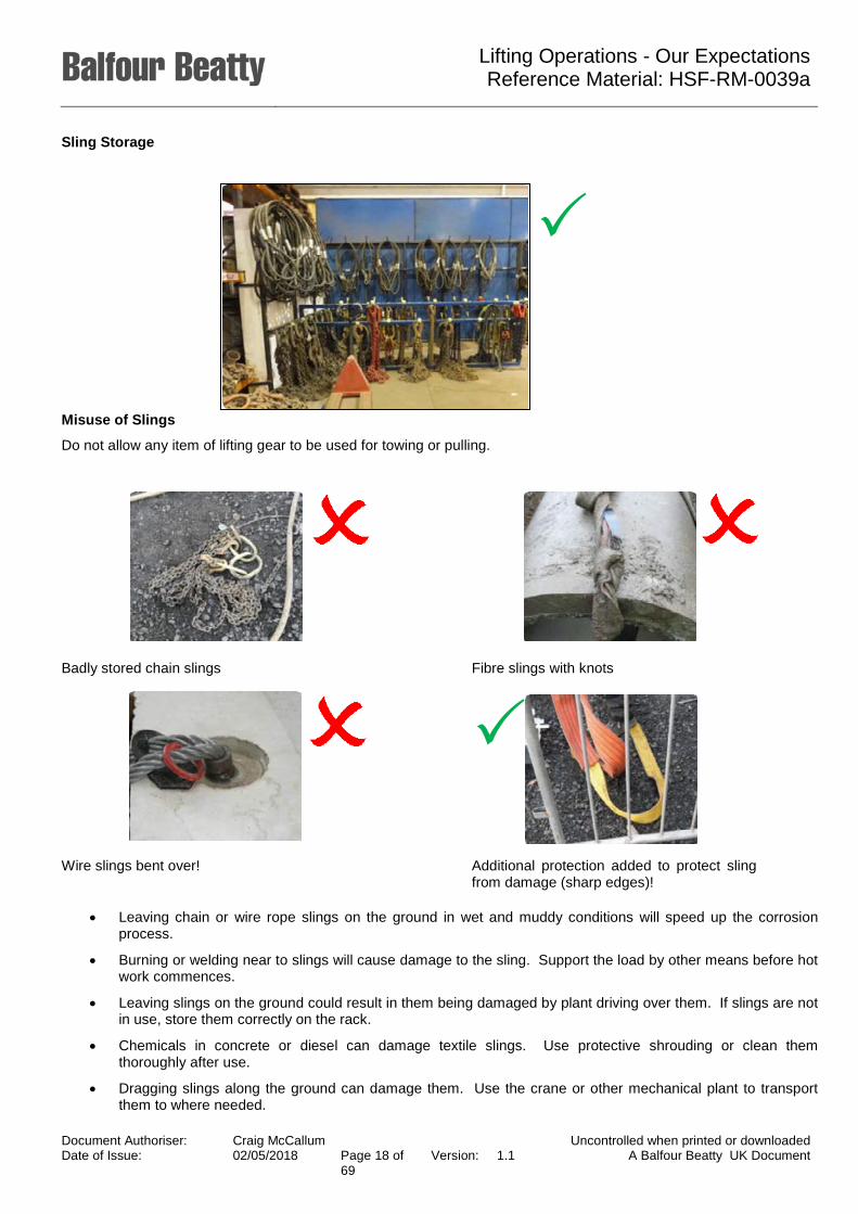
Sling Storage
Misuse of Slings
Do not allow any item of lifting gear to be used for towing or pulling.
Badly stored chain slings Fibre slings with knots
Wire slings bent over! Additional protection added to protect sling
from damage (sharp edges)!
• Leaving chain or wire rope slings on the ground in wet and muddy conditions will speed up the corrosion process.
• Burning or welding near to slings will cause damage to the sling. Support the load by other means before hot work commences.
• Leaving slings on the ground could result in them being damaged by plant driving over them. If slings are not in use, store them correctly on the rack.
• Chemicals in concrete or diesel can damage textile slings. Use protective shrouding or clean them thoroughly after use.
• Dragging slings along the ground can damage them. Use the crane or other mechanical plant to transport them to where needed.
Document Authoriser: Craig McCallum Uncontrolled when printed or downloaded Date of Issue: 02/05/2018 Page 18 of
69 Version: 1.1 A Balfour Beatty UK Document
Lifting Operations - Our Expectations Reference Material: HSF-RM-0039a
• Using a hammer or your foot to tighten the choke hitch may damage the sling. Allow the choke hitch to find
its natural angle of bite.
• Always hook back the slings to the master link or remove them from the crane hook when the slings are unused. Allowing them to swing will cause damage to the crane jib or become trapped.
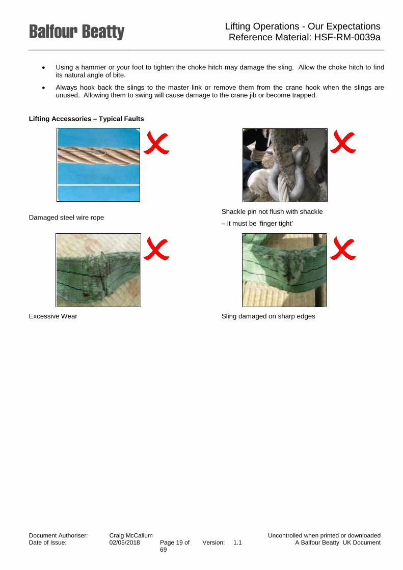
Lifting Accessories – Typical Faults
Damaged steel wire rope Shackle pin not flush with shackle
– it must be ‘finger tight’
Excessive Wear Sling damaged on sharp edges
Document Authoriser: Craig McCallum Uncontrolled when printed or downloaded Date of Issue: 02/05/2018 Page 19 of
69 Version: 1.1 A Balfour Beatty UK Document

Lifting Operations - Our Expectations Reference Material: HSF-RM-0039a
Inspection and Maintenance
Slings
• Regularly inspect slings and, in the event of defects, quarantine and refer to Competent Person for re-thorough examination
• Slings may be cleaned with clean water
• Heat damage can be generated by friction
• Illegible markings
• Damaged or cuts to the surface, edges and outer cover
• Damaged stitching
• Exposed inner core
• Hard spots
• Burns and chemical damage (softening of the fibres)
• Records of inspections must be made on a Lifting Accessories Weekly Inspection Form
• Sunlight/UV can also damage the sling
Chain Slings
• Regularly inspect slings and, in the event of defects, quarantine and refer to Competent Person for thorough examination
• Do not allow them to lie on the floor, become damaged and rusty
• Storage should be dry, clean and free from contaminates and protected from corrosion (lightly oiling)
• Illegible markings
• Distortion of fittings
• Worn
• Stretched
• Bent or twisted links
• Ineffective safety catches
• Cuts
• Nicks
• Gouges
• Corrosion
• Heat discolouration and welding splatter
• Do not attempt lifting operation unless you understand the safe use, slinging procedure and mode factors (permissible configurations)
Textile Slings
Fabric slings come in 2 types, flat web slings and round slings
• Flat slings are made of woven polyester and can be Simplex, Duplex or Quadplex depending on the number of layers
• Round Slings have an abrasion resistant outer cover with the load-bearing fibres inside
• The lifting capacity of a sling is given by a colour code and the tag stitched into the sling
• The tag must include as a minimum:
o The Working Load Limit Document Authoriser: Craig McCallum Uncontrolled when printed or downloaded Date of Issue: 02/05/2018 Page 20 of
69 Version: 1.1 A Balfour Beatty UK Document

Lifting Operations - Our Expectations Reference Material: HSF-RM-0039a
o The Safe working Load for given configurations
o An identification number
o The standard colour codes and working load limits in the UK are as follows:
Colour Width
Safe Working Load Tonnes
mm WLL Choke hitch Basket hitch
0° 0°-45° 45°-60° Violet 50 1 0,8 2 1,4 1 Green 60 2 1,6 4 2,8 2 Yellow 90 3 2,4 6 4,2 3 Grey 120 4 3,2 8 5,6 4 Red 150 5 4 10 7 5 Blue 240 8 6,4 16 11,2 8
1 0,8 2 1,4 1
• Always inspect a sling before use and do not use if it has been damaged. Ensure it is removed from service and report it to your supervisor.
• The sling must not be used on loads with sharp edges unless the edges are protected with suitable packing.
• Do not use a sling if it has been cut or shows signs of heavy abrasion/contamination.
• Do not leave slings on the ground where they can be tracked over by plant.
• Do not trap a sling beneath the load when placing the load onto the ground or lorry bed. Use timber strips so the sling can be easily removed.
• Do not use a sling if it has been heavily contaminated by oils or chemicals.
• Do not use a sling if it has become wet and has frozen in extremely cold temperatures.
• Do not use a sling if it has been subjected to extreme heat (e.g. burning or welding).
• Do not tie slings together or use a sling with a knot or twist.
Single Trip Slings
To reduce the risk of working at height on the back of delivery vehicles/trailers, single trip slings can be used to pre-sling loads prior to shipment.
Do not climb on to the trailer to attach slings to the crane hook unless suitable edge protection, fall restraint or fall arrest measures are in place.
The slings supplied are flat woven webbing slings, made of man-made fibre for general purpose use.
Single trip slings will state the scope of use on the safe working load tag.
The slings are thoroughly examined in the same way as other slings and lifting accessories and, to comply with legislation will have certificates of thorough examination.
Document Authoriser: Craig McCallum Uncontrolled when printed or downloaded Date of Issue: 02/05/2018 Page 21 of
69 Version: 1.1 A Balfour Beatty UK Document
Lifting Operations - Our Expectations Reference Material: HSF-RM-0039a
Check that the slings are still correctly attached to the load prior to placing them on the crane hook and that they are the correct capacity for the load being lifted.
Check that the slings have not been damaged during transit and look for cuts, tears and signs of heavy abrasion.
Check that slings are not trapped between loads prior to lifting.
Report any defects found to your supervisor.
Ensure that the slings are not trapped and damaged when placing the load on the ground. If the slings remain attached to the load after lifting from the trailer the slings must be checked again before the load can be lifted.
The load can be lifted once more only, to its point of use.
Once any sling has been removed from the load it must be destroyed. The sling should be cut so that it cannot be reused by others.
Ensure that the slings are placed in the correct skips on site and not left to accumulate.
Securing Loads for Transport
The responsibility for securing and un-securing the load to the vehicle is with the vehicle Operator.
The Slinger Signaller must check the load prior to lifting to ensure no loose
material or equipment has been left on the load.
The security and stability of every load must be checked before it is placed on the trailer. The Slinger Signaller must carry out a trial lift when the load is approximately 200mm above the loading area.
Stake post trailers and load ratchet straps are often used to secure the load onto the trailer. Before unloading the Slinger Signaller must check that the load cannot move before the straps are released from the load.
Whether loading or unloading, lifting will only begin when the Slinger Signaller is satisfied it is safe to do so.
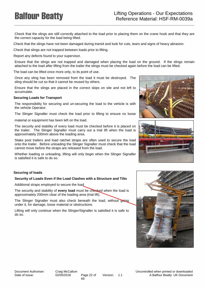
Securing of loads
Security of Loads Even if the Load Clashes with a Structure and Tilts
Additional straps employed to secure the load
The security and stability of every load must be checked when the load is approximately 200mm clear of the loading area (trial lift).
The Slinger Signaller must also check beneath the load, without going under it, for damage, loose material or obstructions.
Lifting will only continue when the Slinger/Signaller is satisfied it is safe to do so.
Document Authoriser: Craig McCallum Uncontrolled when printed or downloaded Date of Issue: 02/05/2018 Page 22 of
69 Version: 1.1 A Balfour Beatty UK Document

Lifting Operations - Our Expectations Reference Material: HSF-RM-0039a
Lifting by Telescopic Handler
The activity in the following images is common, but is it correct?
Lifting on one fork Attachment and load incorrectly positioned
Incorrect attachment Not designed to be lifted by fork lifts
This could be the result.
Document Authoriser: Craig McCallum Uncontrolled when printed or downloaded Date of Issue: 02/05/2018 Page 23 of
69 Version: 1.1 A Balfour Beatty UK Document
Lifting Operations - Our Expectations Reference Material: HSF-RM-0039a
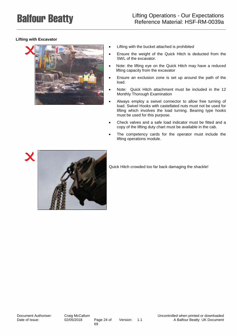
Lifting with Excavator
• Lifting with the bucket attached is prohibited
• Ensure the weight of the Quick Hitch is deducted from the SWL of the excavator.
• Note: the lifting eye on the Quick Hitch may have a reduced lifting capacity from the excavator
• Ensure an exclusion zone is set up around the path of the load.
• Note: Quick Hitch attachment must be included in the 12 Monthly Thorough Examination
• Always employ a swivel connector to allow free turning of load. Swivel Hooks with castellated nuts must not be used for lifting which involves the load turning. Bearing type hooks must be used for this purpose.
• Check valves and a safe load indicator must be fitted and a copy of the lifting duty chart must be available in the cab.
• The competency cards for the operator must include the lifting operations module.
Quick Hitch crowded too far back damaging the shackle!
Document Authoriser: Craig McCallum Uncontrolled when printed or downloaded Date of Issue: 02/05/2018 Page 24 of
69 Version: 1.1 A Balfour Beatty UK Document
Lifting Operations - Our Expectations Reference Material: HSF-RM-0039a
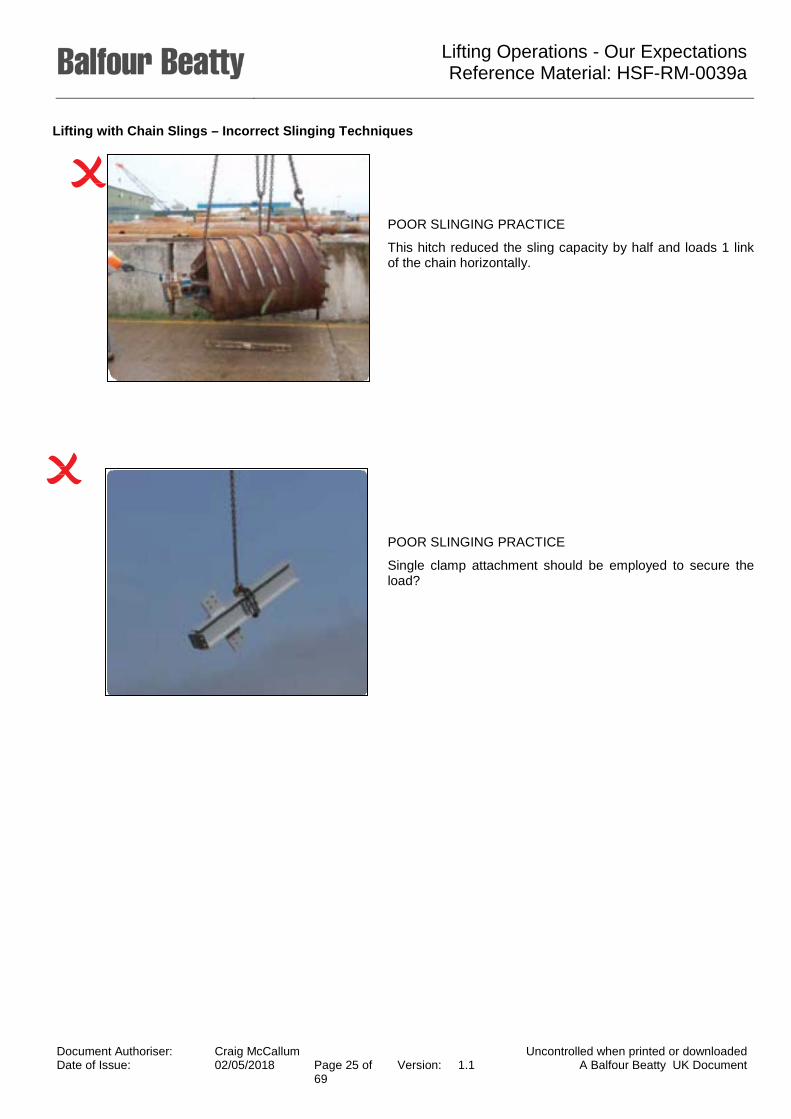
Lifting with Chain Slings – Incorrect Slinging Techniques
POOR SLINGING PRACTICE
This hitch reduced the sling capacity by half and loads 1 link of the chain horizontally.
POOR SLINGING PRACTICE
Single clamp attachment should be employed to secure the load?
Document Authoriser: Craig McCallum Uncontrolled when printed or downloaded Date of Issue: 02/05/2018 Page 25 of
69 Version: 1.1 A Balfour Beatty UK Document

Lifting Operations - Our Expectations Reference Material: HSF-RM-0039a
Loose Material on Loads
Close supervision required to discourage short cuts.
No loose items should be left on loads when they are lifted. If components cannot be secured they must be in a stillage and lifted separately.
Stillages
• 4 leg chain slings wrapped around the corner posts
• Beware of rusted base.
Rule of Thumb – Working angles of chain slings must never exceed 90° as best practice.
Note: when slings are used in choke hitch the Working Load Limit should be reduced by 20%.
Document Authoriser: Craig McCallum Uncontrolled when printed or downloaded Date of Issue: 02/05/2018 Page 26 of
69 Version: 1.1 A Balfour Beatty UK Document
Lifting Operations - Our Expectations Reference Material: HSF-RM-0039a
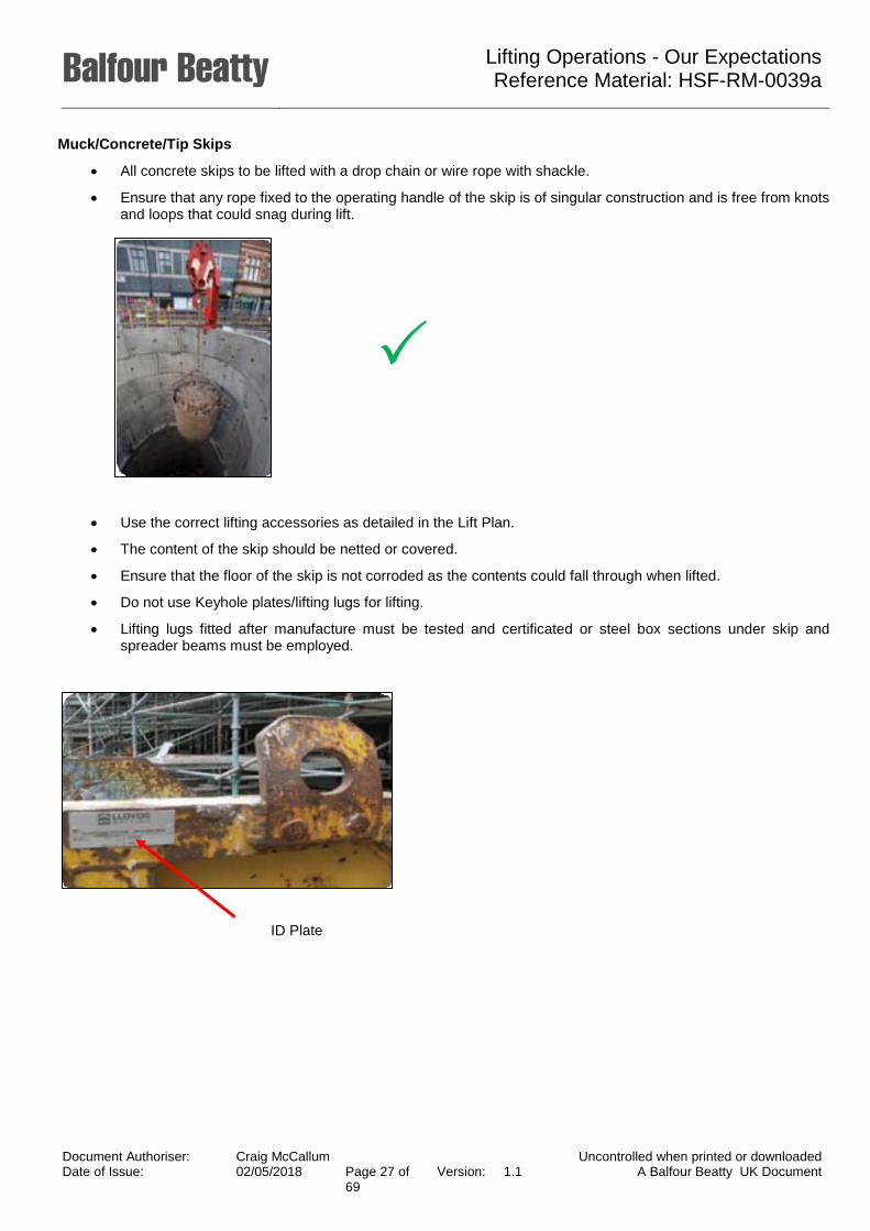
Muck/Concrete/Tip Skips
• All concrete skips to be lifted with a drop chain or wire rope with shackle.
• Ensure that any rope fixed to the operating handle of the skip is of singular construction and is free from knots and loops that could snag during lift.
• Use the correct lifting accessories as detailed in the Lift Plan.
• The content of the skip should be netted or covered.
• Ensure that the floor of the skip is not corroded as the contents could fall through when lifted.
• Do not use Keyhole plates/lifting lugs for lifting.
• Lifting lugs fitted after manufacture must be tested and certificated or steel box sections under skip and spreader beams must be employed.
ID Plate
Document Authoriser: Craig McCallum Uncontrolled when printed or downloaded Date of Issue: 02/05/2018 Page 27 of
69 Version: 1.1 A Balfour Beatty UK Document

Lifting Operations - Our Expectations Reference Material: HSF-RM-0039a
Palletised Material
• Drop chain sling to be employed.
• Crane forks with cage or net.
• Ensure net or cage is in good order and secured to the fork attachment.
• Net or cage only to assist securing the load.
• Select suitable size of net in relation to the smallest item.
• Familiarisation training required.
Lifting Points
• Not all lifting points are designed for lifting the whole load. Check the labelling or the Operator’s Manual for information about the specific item if it is not identified.
• Check that the lifting point is not deformed, damaged, cracked or has signs of significant wear.
• Some lifting points are only designed for vertical lifts (0°sling angle). Check the Lift Plan and manufacturer’s instructions for the particular load to be lifted.
• If you are uncertain if an attachment point is used for lifting, don’t use it. Stop work and check with your supervisor.
Document Authoriser: Craig McCallum Uncontrolled when printed or downloaded Date of Issue: 02/05/2018 Page 28 of
69 Version: 1.1 A Balfour Beatty UK Document

Lifting Operations - Our Expectations Reference Material: HSF-RM-0039a
• A double wrapped choke hitch using chains or slings
must be used when lifting steel bundles.
• The load must be lifted, level and not tipped to one side. Carry out a trial lift to check the slings are positioned correctly and the centre of gravity is beneath the crane hook.
• Do not lift using the tie wires.
• Take care when lifting that the load is not fouling on an adjacent load.
• Always place the load on timber skids to help release the slings from under the load.
• When landing reinforcement always consider who is going to move the steel bundle next and how are they going to get access.
• Use the correct gloves identified in the risk assessment. Steel may have sharp ‘burs’.
• When lifting and placing cages always attach the slings in the position identified on the load and in the Lift Plan.
• Ideally keep the sling angle between 45° and 60°. A greater angle could damage the load and result in it falling from height.
• Always use tag lines to control the movement of the load.
• Do not lift on bars or helicals that are only secured by tie wires.
• Confirm lifting eyes are certificated and tagged, otherwise undersling.
• Drop chain sling to be employed for single attachment.
• If there are no dedicated lifting points the Appointed Person must identify the correct lifting method
Note: check lifting capacity of lifting points on bowsers and tanks
Document Authoriser: Craig McCallum Uncontrolled when printed or downloaded Date of Issue: 02/05/2018 Page 29 of
69 Version: 1.1 A Balfour Beatty UK Document

Lifting Operations - Our Expectations Reference Material: HSF-RM-0039a
Take care with lifting or ‘live loads’ such as 45 gallon drums, bowsers and water tanks. The load can be very unstable and the centre of gravity may shift during movement, particularly if it is half full.
Often the weight of the content is not included in the SWL of the lifting points.
Pipe and Hose Lifting
Hoses are best stored in stillages as they are easier to handle. Hoses must be secured within the stillage to prevent movement of the load during the lift and hoses falling from the stillage.
Document Authoriser: Craig McCallum Uncontrolled when printed or downloaded Date of Issue: 02/05/2018 Page 30 of
69 Version: 1.1 A Balfour Beatty UK Document

Lifting Operations - Our Expectations Reference Material: HSF-RM-0039a
The exception would be when handling flexi hose on CFA sites. Hoses must be lifted as a coil and must be tied together, with the slings attached in choke hitch. Hoses lifted by a single point can kink and be damaged internally.
Document Authoriser: Craig McCallum Uncontrolled when printed or downloaded Date of Issue: 02/05/2018 Page 31 of
69 Version: 1.1 A Balfour Beatty UK Document
Lifting Operations - Our Expectations Reference Material: HSF-RM-0039a
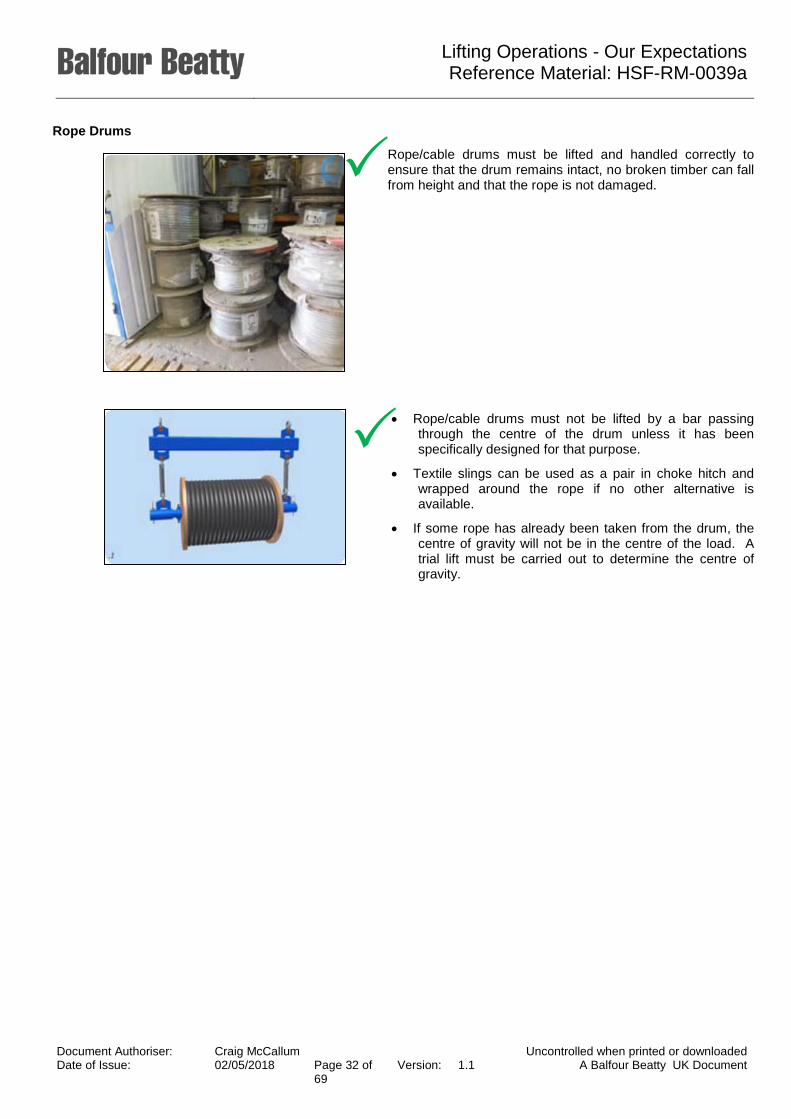
Rope Drums
Rope/cable drums must be lifted and handled correctly to ensure that the drum remains intact, no broken timber can fall from height and that the rope is not damaged.
• Rope/cable drums must not be lifted by a bar passing through the centre of the drum unless it has been specifically designed for that purpose.
• Textile slings can be used as a pair in choke hitch and wrapped around the rope if no other alternative is available.
• If some rope has already been taken from the drum, the centre of gravity will not be in the centre of the load. A trial lift must be carried out to determine the centre of gravity.
Document Authoriser: Craig McCallum Uncontrolled when printed or downloaded Date of Issue: 02/05/2018 Page 32 of
69 Version: 1.1 A Balfour Beatty UK Document

Lifting Operations - Our Expectations Reference Material: HSF-RM-0039a
Plunge Columns
• Plunge columns can weigh anything from 3t to 35t depending upon design requirements. They represent a particular challenge to site as they are generally very long and need to be lifted horizontally and vertically. Placing of the plunge column must be taken with care as the steel must be positioned accurately.
• The plunge column will have designed lifting heads for both horizontal and vertical lifting - these will be connected to the column prior to lifting. The lifting accessories will be selected depending upon the weight and will be detailed in the Lift Plan. The SWL of the lifting accessories must be at least 25% more than the weight of the plunge column.
• Slingers must ensure that the bore hole is suitably backfilled and/or fenced off at the earliest opportunity when the casing is removed the following shift.
Document Authoriser: Craig McCallum Uncontrolled when printed or downloaded Date of Issue: 02/05/2018 Page 33 of
69 Version: 1.1 A Balfour Beatty UK Document

Lifting Operations - Our Expectations Reference Material: HSF-RM-0039a
Kelly Bars
• A Kelly Bar is a very common piece of equipment on a piling rig and often will be the heaviest item on site.
• When delivered to site the Kelly Bar must be pre-slung with kidney chains and must be lifted horizontally from the vehicle. The kidney chains must have a safe working load of 10t and must be used in conjunction with the 4 leg chain slings kept on site. Kelly Bars weigh from 2.6t to 10.7t within BBGE’s fleet.
• A Kelly Bar will also be lifted from horizontal position to vertical in order to place it within the rotary table on the rig. Often a service crane will be operating in close proximity to the mast of the rig and the Slinger Signaller must be aware of the location of the crane ‘cat-head’ in relation to the rig mast. A detailed Lift Plan must be in place.
• Kidney chains must be left on the Kelly Bar when returning it to the depot to assist with unloading.
Document Authoriser: Craig McCallum Uncontrolled when printed or downloaded Date of Issue: 02/05/2018 Page 34 of
69 Version: 1.1 A Balfour Beatty UK Document

Lifting Operations - Our Expectations Reference Material: HSF-RM-0039a
Pile Casings
• Pile casings are amongst the largest loads lifted on a piling site and present many hazards during lifting operations.
• Casing hooks are typically used on site to lift and transfer casings. The angle between the sling legs should be around 45° to 60° ensuring sufficient clamping force to prevent the hooks from slipping. The chain sling length must be checked before the lift in order to achieve this.
• Casings that are relatively small in diameter could be pre-slung eliminating the need to access trailer beds.
• Ensure that casings are chocked correctly before releasing ratchet straps and that the load is chocked on the ground before releasing the tension from the slings.
• Tag lines must be used in order to control the load.
• Never leave a casing free standing.
Document Authoriser: Craig McCallum Uncontrolled when printed or downloaded Date of Issue: 02/05/2018 Page 35 of
69 Version: 1.1 A Balfour Beatty UK Document

Lifting Operations - Our Expectations Reference Material: HSF-RM-0039a
Pile Cages
• Lifting of pile cages are amongst the most common lifts that take place on a piling site. Some cages are small in diameter and relatively simple in design and often it is easy to take cage lifting for granted. Cages may only be tack welded or tie wired together and must be handled with care to prevent damage or separation of the bars.
• Ensure that the Lift Plan has identified which slings to use and where they should be attached.
• Other pile cages are very large in diameter and are complex in design. These cages may come in sections and require splicing. Specialist lifting accessories may be needed and with very large cages such as those in diaphragm walling. A tandem lift will be required to lift the cage into the air.
• Tandem lifts are classed as complex lifts under BS 7121 Safe Use of Cranes. A site specific Lifting Plan must be prepared and briefed to all operatives involved in the operation. Cages must be inspected before being lifted. Any loose bars identified must be reported to line management and removed.
Document Authoriser: Craig McCallum Uncontrolled when printed or downloaded Date of Issue: 02/05/2018 Page 36 of
69 Version: 1.1 A Balfour Beatty UK Document
Lifting Operations - Our Expectations Reference Material: HSF-RM-0039a
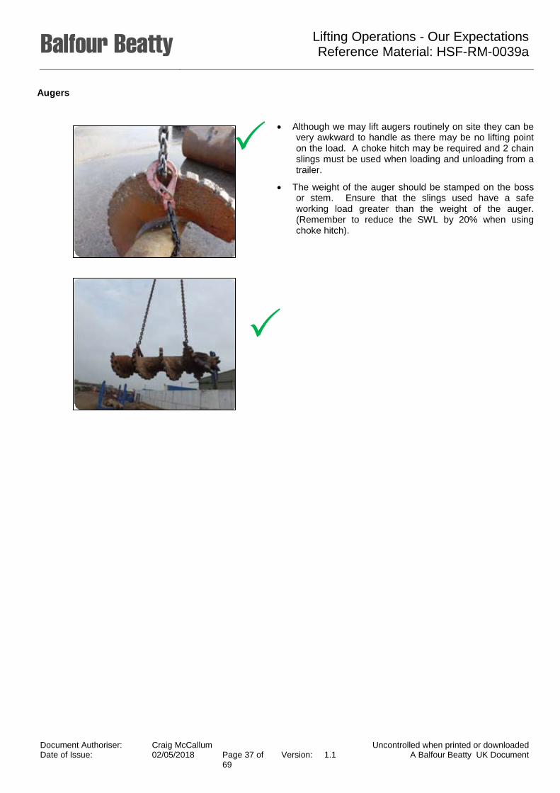
Augers
• Although we may lift augers routinely on site they can be very awkward to handle as there may be no lifting point on the load. A choke hitch may be required and 2 chain slings must be used when loading and unloading from a trailer.
• The weight of the auger should be stamped on the boss or stem. Ensure that the slings used have a safe working load greater than the weight of the auger. (Remember to reduce the SWL by 20% when using choke hitch).
Document Authoriser: Craig McCallum Uncontrolled when printed or downloaded Date of Issue: 02/05/2018 Page 37 of
69 Version: 1.1 A Balfour Beatty UK Document

Lifting Operations - Our Expectations Reference Material: HSF-RM-0039a
Digging and Cleaning Buckets
• Use the lifting eyes provided to move around site with a tag line attached.
• Before any lift is attempted check you have the correct lifting attachments.
• Due to the way digging and cleaning buckets are made it can be difficult to stand them upright. Where possible place them in the auger stands. If not possible, a pilot hole made by the auger should be used, making sure the buckets are secure before removing any slings or chains. A permit to break ground must be in place and permission from site supervision before this is done.
• Buckets should be pre-slung to help with unloading unless a fork truck can be used.
Document Authoriser: Craig McCallum Uncontrolled when printed or downloaded Date of Issue: 02/05/2018 Page 38 of
69 Version: 1.1 A Balfour Beatty UK Document

Lifting Operations - Our Expectations Reference Material: HSF-RM-0039a
Core Barrels
• Always use lifting eyes provided when lifting core barrels around site with a tag line attached to control the load.
• Only lift with a kelly pin through the hole in the box if the Kelly pin is secured in place with the correct split pin.
• When unloading from a 40ft wagon use a fork truck if available, otherwise cradle the load using textile slings or chain brothers.
• When using textile slings always protect the webbing from damage from any sharp edges. Always check you have the correct sling or chain for task and confirm the safe working load of the attachment method.
• Always ensure any load is stable and cannot move or fall before attempting to remove slings or chains.
X
Document Authoriser: Craig McCallum Uncontrolled when printed or downloaded Date of Issue: 02/05/2018 Page 39 of
69 Version: 1.1 A Balfour Beatty UK Document

Lifting Operations - Our Expectations Reference Material: HSF-RM-0039a
Vibro Flots
• The standard Vibro flots within UK operations, range from 6.5 metres to 12 metres and can weigh up to 4.5t. They are awkward to lift as the centre of gravity is not in the centre of the load. The stinger and the isolator are the heaviest components of the flot and the slings selected should be positioned correctly so the load is evenly applied in both slings.
• Vibro flots should arrive on site pre-slung with two 5ft red textile slings in choke hitch. These are then attached to the chain slings on the crane or lorry loader. The Slinger and Crane Operator should check that the SWL of the chain slings are greater than the weight of the Vibro flot.
• Slingers should ensure that the slings are left on the flot when loading it on the wagon to return it to the depot. This will assist the slingers with unloading.
Document Authoriser: Craig McCallum Uncontrolled when printed or downloaded Date of Issue: 02/05/2018 Page 40 of
69 Version: 1.1 A Balfour Beatty UK Document

Lifting Operations - Our Expectations Reference Material: HSF-RM-0039a
Wood Bundles
• Wrapped with 2 leg chain slings or fibre slings for timber in finishings in a choke hitch.
• Ensure wood to be lifted is of equal length and the slings secure all the timber within the bundle. Note – may have to split the timber vertically to secure all timber contained.
• Avoid battering down and exceeding the sling angle directly above the load 120°.
Rule of Thumb – working angles of chain slings must never exceed 90° as best practice.
Note: when slings are used in choke hitch the Working Load Limit should be reduced by 20%.
• This load will collapse into a round load.
• Ensure all materials are secured, should the load accidentally strike building.
• Load should be wrapped or banded before lifting.
Max 120° Rule
Document Authoriser: Craig McCallum Uncontrolled when printed or downloaded Date of Issue: 02/05/2018 Page 41 of
69 Version: 1.1 A Balfour Beatty UK Document

Lifting Operations - Our Expectations Reference Material: HSF-RM-0039a
Column Shutter
• Chain to be securely attached to the lifting points as defined in the manufacturer’s guidance.
• The guidance also offers the exact number of clamps to secure the shutter – avoiding overloading the lifting eyes.
• Beware of loose concrete and debris on the shutter before lifting.
Note: Reduce the out of service wind speed when increasing the surface area of the load.
Wall Shutter
• Chain to be securely attached to the lifting points as defined in the manufacturer’s guidance.
• The guidance also offers the exact number of clamps to secure the shutter – avoiding overloading the lifting eyes.
• Beware of loose concrete and debris on the shutter before lifting.
Note: reduce the out of service wind speed when increasing the surface area of the load.
Document Authoriser: Craig McCallum Uncontrolled when printed or downloaded Date of Issue: 02/05/2018 Page 42 of
69 Version: 1.1 A Balfour Beatty UK Document
Lifting Operations - Our Expectations Reference Material: HSF-RM-0039a
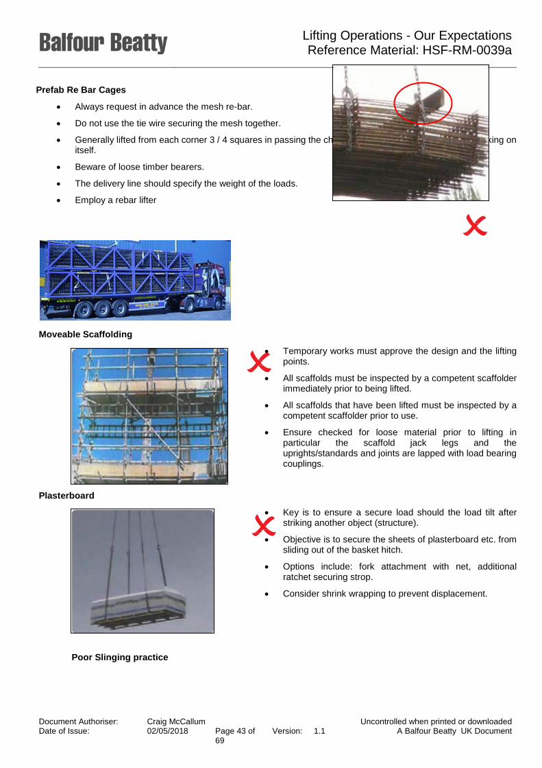
Prefab Re Bar Cages
• Always request in advance the mesh re-bar.
• Do not use the tie wire securing the mesh together.
• Generally lifted from each corner 3 / 4 squares in passing the chain slings through and back round choking on itself.
• Beware of loose timber bearers.
• The delivery line should specify the weight of the loads.
• Employ a rebar lifter
Moveable Scaffolding
• Temporary works must approve the design and the lifting points.
• All scaffolds must be inspected by a competent scaffolder immediately prior to being lifted.
• All scaffolds that have been lifted must be inspected by a competent scaffolder prior to use.
• Ensure checked for loose material prior to lifting in particular the scaffold jack legs and the uprights/standards and joints are lapped with load bearing couplings.
Image of poor quality scaffolding
Plasterboard
• Key is to ensure a secure load should the load tilt after striking another object (structure).
• Objective is to secure the sheets of plasterboard etc. from sliding out of the basket hitch.
• Options include: fork attachment with net, additional ratchet securing strop.
• Consider shrink wrapping to prevent displacement.
Poor Slinging practice
Document Authoriser: Craig McCallum Uncontrolled when printed or downloaded Date of Issue: 02/05/2018 Page 43 of
69 Version: 1.1 A Balfour Beatty UK Document
Lifting Operations - Our Expectations Reference Material: HSF-RM-0039a
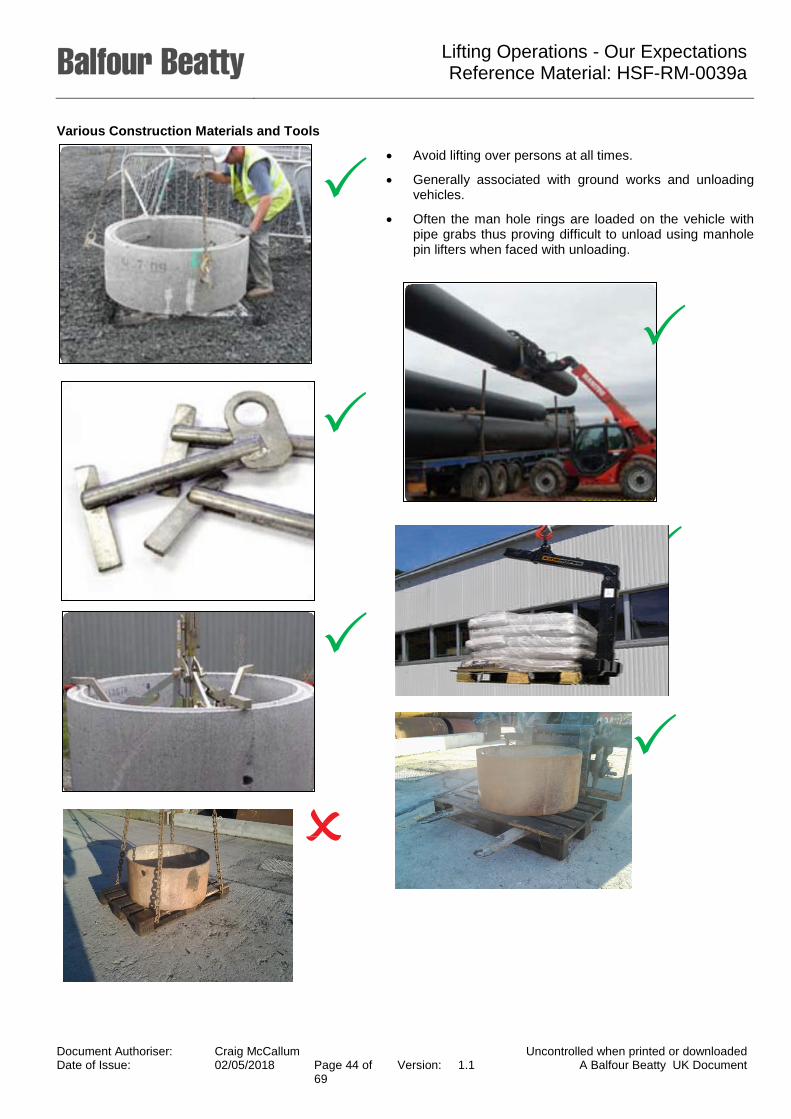
Various Construction Materials and Tools
• Avoid lifting over persons at all times.
• Generally associated with ground works and unloading vehicles.
• Often the man hole rings are loaded on the vehicle with pipe grabs thus proving difficult to unload using manhole pin lifters when faced with unloading.
Document Authoriser: Craig McCallum Uncontrolled when printed or downloaded Date of Issue: 02/05/2018 Page 44 of
69 Version: 1.1 A Balfour Beatty UK Document
Lifting Operations - Our Expectations Reference Material: HSF-RM-0039a
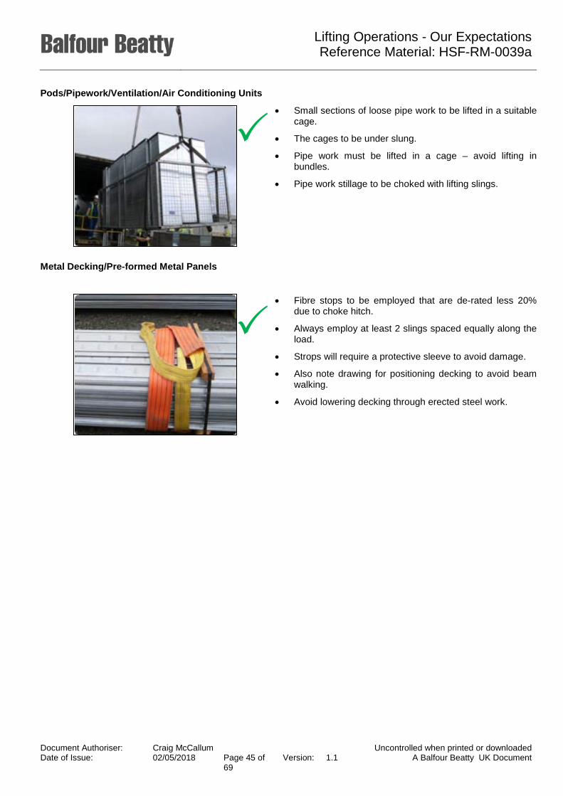
Pods/Pipework/Ventilation/Air Conditioning Units
• Small sections of loose pipe work to be lifted in a suitable cage.
• The cages to be under slung.
• Pipe work must be lifted in a cage – avoid lifting in bundles.
• Pipe work stillage to be choked with lifting slings.
Metal Decking/Pre-formed Metal Panels
• Fibre stops to be employed that are de-rated less 20% due to choke hitch.
• Always employ at least 2 slings spaced equally along the load.
• Strops will require a protective sleeve to avoid damage.
• Also note drawing for positioning decking to avoid beam walking.
• Avoid lowering decking through erected steel work.
Document Authoriser: Craig McCallum Uncontrolled when printed or downloaded Date of Issue: 02/05/2018 Page 45 of
69 Version: 1.1 A Balfour Beatty UK Document

Lifting Operations - Our Expectations Reference Material: HSF-RM-0039a
Windows/Stillages of Concrete Panels/Glass Frames
• Ensure the window sucker has a backup power supply.
• Daily checks undertaken on the seals. The radio controlled systems prohibited from BB projects due to mobile phone interference.
• Do not use in the rain or damp condition.
• Always clean and dry both the sucker and window before lifting.
• Additional slings required to act as a fail safe.
• Ensure operators received manufacturer’s instruction
• The windows on the stillages must be banded together.
• Check adequate bands to restrain the glass during lifting
• Often the lifting eyes are not tested, failing that, suggest fibre strops under-slung the stillage and the glass.
Document Authoriser: Craig McCallum Uncontrolled when printed or downloaded Date of Issue: 02/05/2018 Page 46 of
69 Version: 1.1 A Balfour Beatty UK Document

Lifting Operations - Our Expectations Reference Material: HSF-RM-0039a
ACRO Props and Loose Material
• Options for ACROW prop include wrapped in cargo net then double wrapped in slings.
• If lifting loose material worth investing in goods cage that may double for rescue (note reduce to 6 monthly thorough examinations).
Note: the larger the cage the less weight the crane can lift.
Document Authoriser: Craig McCallum Uncontrolled when printed or downloaded Date of Issue: 02/05/2018 Page 47 of
69 Version: 1.1 A Balfour Beatty UK Document

Lifting Operations - Our Expectations Reference Material: HSF-RM-0039a
Structural Steel
• Preference – Single point secure/positive attachment.
• Last resort when double wrapped, secondary fail safe system required to prevent load being dropped.
• Smaller sections including tubular or bracing then suitable rated fibre strop to be employed.
• Columns lifted through pre-drilled sized shackle hole.
• Only box sections and flat bracing where either shackle or bolt on clamp restricted then last resort fibre strops choked.
• Note: Choke hitch reduced lifting capacity of slings by 20%.
• Always use a tag line to control the load (avoid knots etc. in tag line that could snag).
Document Authoriser: Craig McCallum Uncontrolled when printed or downloaded Date of Issue: 02/05/2018 Page 48 of
69 Version: 1.1 A Balfour Beatty UK Document

Lifting Operations - Our Expectations Reference Material: HSF-RM-0039a
Bulk Bag and Slabs
Best practice for lifting bags
Additional straps employed to secure load over the shrink wrapping
Document Authoriser: Craig McCallum Uncontrolled when printed or downloaded Date of Issue: 02/05/2018 Page 49 of
69 Version: 1.1 A Balfour Beatty UK Document

Lifting Operations - Our Expectations Reference Material: HSF-RM-0039a
Concrete Agitators
• The difficulty with lifting agitators is that they are large and heavy. The centre of gravity can be awkward to assess and to overcome this lifting points have been manufactured on to the equipment.
• Agitators can weigh up to 12t and 20t, four leg chain slings must be used.
• Both drum and water tank must be empty before lifting. Slingers and Crane Operators must be aware that dried concrete could remain in the drum and this must be reported to the supervisor and Appointed Person.
• Under no circumstances should the agitator be lifted by the lifting points if the weight of the agitator exceeds the stamped weight of the lifting points.
• Chain slings must be choke hitched around the chassis.
• A tag line must be used to control the movement of the load and assist with positioning the agitator.
Document Authoriser: Craig McCallum Uncontrolled when printed or downloaded Date of Issue: 02/05/2018 Page 50 of
69 Version: 1.1 A Balfour Beatty UK Document

Lifting Operations - Our Expectations Reference Material: HSF-RM-0039a
Precast Piles
• Winching and lifting of pre-cast piles can take place dozens of times each day on a driven piling site and each pile may have been lifted 6 times or more before it eventually reaches its point of use.
• Pile weights can vary dramatically dependent upon their length and size and a chart of pile weights should be readily available on site.
• The Slinger must check that the lifting eyes are intact before attempting a lift and piles must be kept as low as possible during the lift.
• Piles should be lifted and moved in a controlled manner to prevent swing and a tag line should be used by the Slinger Signaller.
• The secondary (safety) sling must be used to secure the pile in the event of lifting eye failure.
Document Authoriser: Craig McCallum Uncontrolled when printed or downloaded Date of Issue: 02/05/2018 Page 51 of
69 Version: 1.1 A Balfour Beatty UK Document

Lifting Operations - Our Expectations Reference Material: HSF-RM-0039a
Tremie Pipes
• The lifting cap must be inspected fully before use and not used if any defect is found. Ensure that the defective cap is quarantined and reported to your supervisor immediately.
• All tremie joints and cables must be compatible. Do not use tremie cables if they are undersized or do not fully insert into the joint.
• All full string of tremie pipe must be lifted using the lifting cap and not the concrete hopper.
• The Slinger must take care when lifting tremies in and out of the rack. Keep hands clear and use poles to manipulate the pipe into the rack.
• If a Relay Signaller is used only the designated Signaller must give signals to the Crane Operator. Keep all other operatives clear.
Tremie lifting cap with correctly attached shackle.
Assemble the tremie string in the rack vertically. Do not lay tremies down!
Document Authoriser: Craig McCallum Uncontrolled when printed or downloaded Date of Issue: 02/05/2018 Page 52 of
69 Version: 1.1 A Balfour Beatty UK Document

Lifting Operations - Our Expectations Reference Material: HSF-RM-0039a
Block Grabs
• Mechanical and hydraulic block grabs are available for lifting packs of concrete blocks, bricks or slabs.
• There are several designs, some are a fully automatic scissor design mechanism and others incorporate hydraulic cylinders to apply the appropriate pressure to safely lift a pack or individual blocks. Both types are shown above. These types of grabs can handle standard packs of concrete blocks, bricks and slabs safely and their simple sturdy construction results in a long service life.
• The grabs can be operated via the RRV without the driver leaving the safety of his vehicle.
• Equipment Operator(s) to have Safe Systems of Work in place for All operational circumstances
• Grabs must only be used by authorised and competent personnel in accordance with mandatory rules, regulations and the equipment operating instructions.
• If adjacent lines are open to traffic, it shall only be used in accordance with the Method Statement for the possession and only if the safe system of work has taken account of gauge exceedance.
• Staff shall be briefed on the safe operation of the machine prior to its use.
• The Slinger must take care when lifting tremies in and out of the rack. Keep hands clear and use poles to manipulate the pipe into the rack.
• The limitations of the RRV to which the machine is attached shall apply.
Typical Mechanical Scissor Block Grab
Document Authoriser: Craig McCallum Uncontrolled when printed or downloaded Date of Issue: 02/05/2018 Page 53 of
69 Version: 1.1 A Balfour Beatty UK Document

Lifting Operations - Our Expectations Reference Material: HSF-RM-0039a
Post Grab Manipulator
• The manipulators can manoeuvre signal posts, pipes and tubes weighing up to 1000kgs and measuring between 70-300mm diameter easily and safely. Sandhurst manipulators have vertical and horizontal attachment rotation, so used in conjunction with the excavator crowd ram, posts can be rotated and tilted through any angle.This compact plate grab will handle all designs of steel sleepers in all pack sizes.
• Clamping is very secure, with each clamp working independently of one another. In use, each clamp stops when meeting resistance, enabling uneven shapes to be handled.For safety, the hydraulic cylinders are fitted with check valves and pressure control valves and for storage and transport the jaws open wider to make it more stable.
• Posts are gripped securely and held firm by nylon pads, fitted to the clamps, preventing load slip and providing post protection.
• These manipulators have continuous rotation and controlled braking, resulting in smooth and accurate control over post setting.
• This attachment is deal for use with RRV excavators from 13 – 30 tonnes.
• Equipment Operator(s) to have Safe Systems of Work in place for All operational circumstances
• Grabs must only be used by authorised and competent personnel in accordance with mandatory rules, regulations and the equipment operating instructions.
• If adjacent lines are open to traffic, it shall only be used in accordance with the Method Statement for the possession and only if the safe system of work has taken account of gauge exceedance.
• Staff shall be briefed on the safe operation of the machine prior to its use.
• The Slinger must take care when lifting tremies in and out of the rack. Keep hands clear and use poles to manipulate the pipe into the rack.
• The limitations of the RRV to which the machine is attached shall apply.
Typical Post Grab Manipulator
Document Authoriser: Craig McCallum Uncontrolled when printed or downloaded Date of Issue: 02/05/2018 Page 54 of
69 Version: 1.1 A Balfour Beatty UK Document
Lifting Operations - Our Expectations Reference Material: HSF-RM-0039a
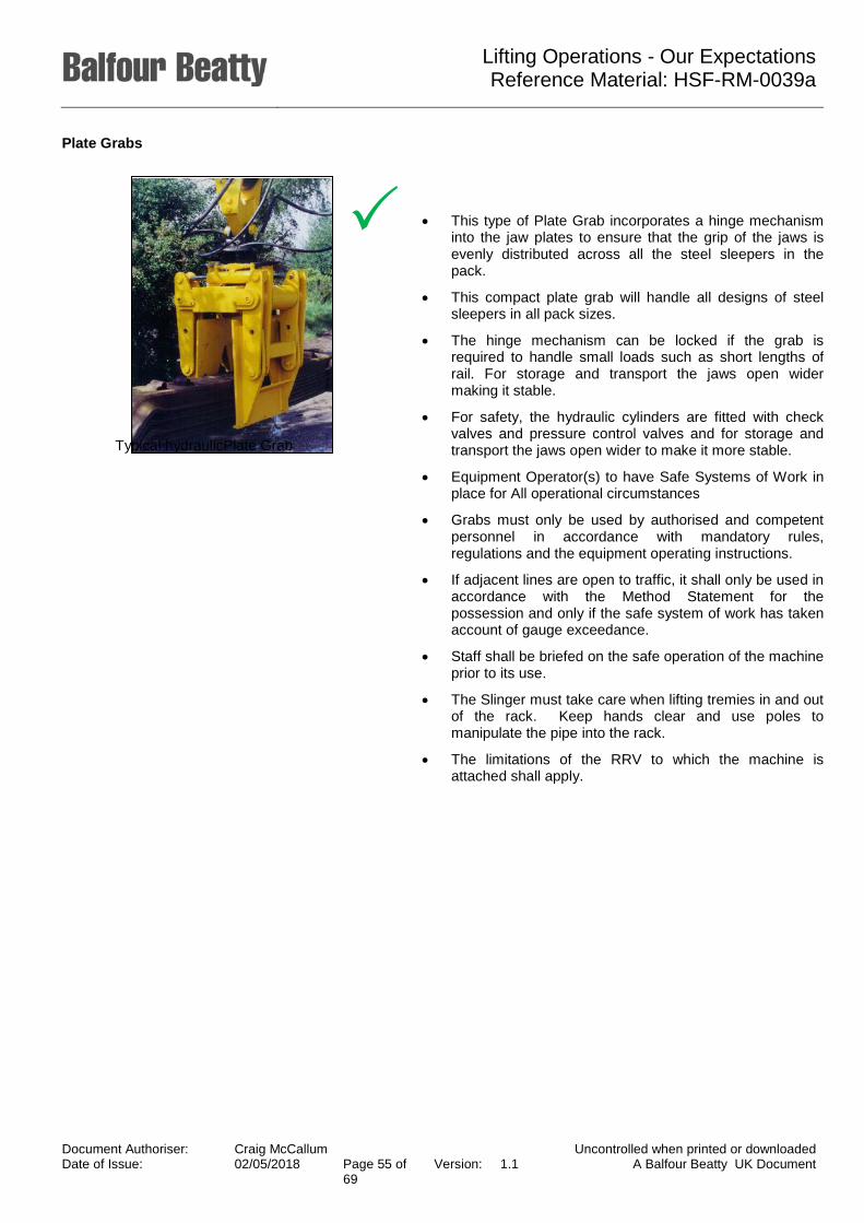
Plate Grabs
• This type of Plate Grab incorporates a hinge mechanism into the jaw plates to ensure that the grip of the jaws is evenly distributed across all the steel sleepers in the pack.
• This compact plate grab will handle all designs of steel sleepers in all pack sizes.
• The hinge mechanism can be locked if the grab is required to handle small loads such as short lengths of rail. For storage and transport the jaws open wider making it stable.
• For safety, the hydraulic cylinders are fitted with check valves and pressure control valves and for storage and transport the jaws open wider to make it more stable.
• Equipment Operator(s) to have Safe Systems of Work in place for All operational circumstances
• Grabs must only be used by authorised and competent personnel in accordance with mandatory rules, regulations and the equipment operating instructions.
• If adjacent lines are open to traffic, it shall only be used in accordance with the Method Statement for the possession and only if the safe system of work has taken account of gauge exceedance.
• Staff shall be briefed on the safe operation of the machine prior to its use.
• The Slinger must take care when lifting tremies in and out of the rack. Keep hands clear and use poles to manipulate the pipe into the rack.
• The limitations of the RRV to which the machine is attached shall apply.
Typical hydraulicPlate Grab
Document Authoriser: Craig McCallum Uncontrolled when printed or downloaded Date of Issue: 02/05/2018 Page 55 of
69 Version: 1.1 A Balfour Beatty UK Document

Lifting Operations - Our Expectations Reference Material: HSF-RM-0039a
Sleeper Loading Grab
• The hydraulic sleeper loading grabs are designed for loading batches of 5 or 7 concrete sleepers, side-by-side.
• The beam length is mechanically adjustable so that it is possible to handle sleepers of different lengths.
• It incorporates a strong and endlessly rotating (360°) hydraulic rotator which allows rapid, exact and high-efficiency operations possible.
• The sleeper loading device may be mounted onto most types of standard RRV excavators.
• Equipment Operator(s) to have Safe Systems of Work in place for All operational circumstances
• The Sleeper Grab must only be used by authorised and competent personnel in accordance with mandatory rules, regulations and the equipment operating instructions.
• If adjacent lines are open to traffic, it shall only be used in accordance with the Method Statement for the possession and only if the safe system of work has taken account of gauge exceedance.
• Staff shall be briefed on the safe operation of the machine prior to its use.
• The Slinger must take care when lifting tremies in and out of the rack. Keep hands clear and use poles to manipulate the pipe into the rack.
• The limitations of the RRV to which the machine is attached shall apply.
Document Authoriser: Craig McCallum Uncontrolled when printed or downloaded Date of Issue: 02/05/2018 Page 56 of
69 Version: 1.1 A Balfour Beatty UK Document

Lifting Operations - Our Expectations Reference Material: HSF-RM-0039a
Bag Lifting Beam
• Bag lifting beams are mandated on Network Rail infrastructure.
• The ballast bag lifter helps improve the safe handling of large bags of rail ballast and has been designed to be robust and portable.
• The ballast bag lifter is available in either a 1 tonne or 2 tonne version with either welded on hooks or swivel safety hooks for additional safety and ease of use.
• Manufactured in two width versions to suit differing bag sizes (800mm – 850mm & 900mm – 970 mm).
• Each beam shall have a valid LOLER certificate.
• The beam shall be subject to all applicable limitations on the Engineering Acceptance certificate of the Road rail Vehicle (RRV) to which it’s attached.
• The beam shall only be used with an RRV whose RCI indicator is active, and the lifting duty is in excess of the beam / load in the most adverse condition.
Document Authoriser: Craig McCallum Uncontrolled when printed or downloaded Date of Issue: 02/05/2018 Page 57 of
69 Version: 1.1 A Balfour Beatty UK Document

Lifting Operations - Our Expectations Reference Material: HSF-RM-0039a
Level Crossing Slab Lifter
• The Crossing slab lifter is designed & built to lift, handle, remove & install all types* of level crossing slabs, in use on NR Infrastructure. The slab lifter unit includes a “tlt-rotator” head, which allows the unit to assume the required angles to manipulate the slabs, (in & out of the track); such that all heavy lifting, (manual handling); is avoided.
• The unit is mechanical / hydraulic in operation, and is compatible with all suitably rigged 360° Excavators**, (Road Rail or otherwise); and promotes improved safety & greater efficiency on site, with increased productivity, and better worksite management
• Equipment Operator(s) to have Safe Systems of Work in place for All operational circumstances
• The attachment must only be used by authorised and competent personnel in accordance with mandatory rules, regulations and the equipment operating instructions
• Staff shall be briefed on the safe operation of the machine prior to its use.
• The limitations of the RRV to which the machine is attached shall apply.
Typical Level Crossing Slab Lifter
Document Authoriser: Craig McCallum Uncontrolled when printed or downloaded Date of Issue: 02/05/2018 Page 58 of
69 Version: 1.1 A Balfour Beatty UK Document

Lifting Operations - Our Expectations Reference Material: HSF-RM-0039a
Panel Lifting Beam
• Rail Panel Lifting Beam has been specifically designed to lift panels of track.
• After the section of rail has been cut or assembled into panels, the beam is hydraulically clamped onto the rails of the panel.
• Optional hydraulic rams then lift the panel clear of the ballast, allowing one Road Rail Vehicle (RRV) to then lift the panel.
• The equipment shall only be operated inside a possession that shall normally include any adjacent lines. In situations where there are more than two lines, a risk assessment shall be carried out to determine if the line separation is sufficient to permit some lines to remain open to traffic.
• Each beam shall have a valid LOLER certificate.
• The beam shall only be used to lift new or serviceable rail of up to 6m in length. Longer lengths of rail may be lifted when the rail is scrap and marked accordingly.
• The beam shall be subject to all applicable limitations on the Engineering Acceptance certificate of the RRV to which it is attached.
• The beam shall only be used with an RRV when the RC! indicator is active, and the lifting duty is in excess of the beam / load in the most adverse condition.
• Only the crane controller shall set the position of the by-pass valve.
• Universal Lifting Beams must be used in pairs for lifting track panels.
• Equipment Operator(s) to have Safe Systems of Work in place for All operational circumstances
• The attachment must only be used by authorised and competent personnel in accordance with mandatory rules, regulations and the equipment operating instructions
• Staff shall be briefed on the safe operation of the machine prior to its use.
• The limitations of the RRV to which the machine is attached shall apply.
Typical panel beam
Document Authoriser: Craig McCallum Uncontrolled when printed or downloaded Date of Issue: 02/05/2018 Page 59 of
69 Version: 1.1 A Balfour Beatty UK Document
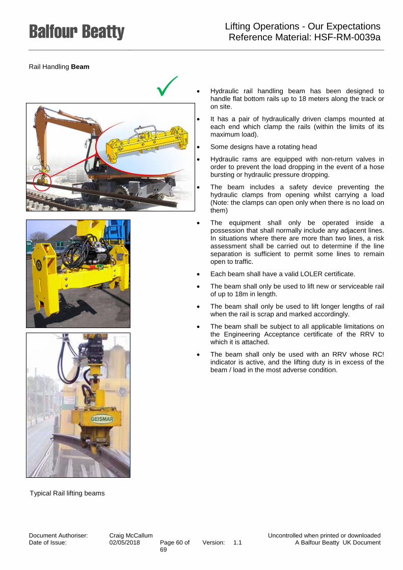
Lifting Operations - Our Expectations Reference Material: HSF-RM-0039a
Rail Handling Beam
• Hydraulic rail handling beam has been designed to handle flat bottom rails up to 18 meters along the track or on site.
• It has a pair of hydraulically driven clamps mounted at each end which clamp the rails (within the limits of its maximum load).
• Some designs have a rotating head
• Hydraulic rams are equipped with non-return valves in order to prevent the load dropping in the event of a hose bursting or hydraulic pressure dropping.
• The beam includes a safety device preventing the hydraulic clamps from opening whilst carrying a load (Note: the clamps can open only when there is no load on them)
• The equipment shall only be operated inside a possession that shall normally include any adjacent lines. In situations where there are more than two lines, a risk assessment shall be carried out to determine if the line separation is sufficient to permit some lines to remain open to traffic.
• Each beam shall have a valid LOLER certificate.
• The beam shall only be used to lift new or serviceable rail of up to 18m in length.
• The beam shall only be used to lift longer lengths of rail when the rail is scrap and marked accordingly.
• The beam shall be subject to all applicable limitations on the Engineering Acceptance certificate of the RRV to which it is attached.
• The beam shall only be used with an RRV whose RC! indicator is active, and the lifting duty is in excess of the beam / load in the most adverse condition.
Typical Rail lifting beams
Document Authoriser: Craig McCallum Uncontrolled when printed or downloaded Date of Issue: 02/05/2018 Page 60 of
69 Version: 1.1 A Balfour Beatty UK Document

Lifting Operations - Our Expectations Reference Material: HSF-RM-0039a
Manual Sleeper Lifting Beam
• The Sleeper Lifting beam is designed for the lifting and handling individual rail sleepers. Sleeper lifting beams are available in various styles with either fixed or adjustable centres, allowing for the differing sleeper spacings.
• In addition depending upon the type of beam, a wide variety of dropper chain configurations and sleeper hooks are available.
• The standard range of lifting and laying beams are configured for loading, with dropper chains fitted at half sleeper spacings. There are 3 leg, 5 leg, 7 leg and 8 leg spacing options available and there is a choice of pandrol or fast clipper lifting hooks.
• The equipment shall only be operated inside a possession that shall normally include any adjacent lines. In situations where there are more than two lines, a risk assessment shall be carried out to determine if the line separation is sufficient to permit some lines to remain open to traffic.
• Each beam shall have a valid LOLER certificate.
• The beam shall be subject to all applicable limitations on the Engineering Acceptance certificate of the RRV to which it is attached.
• The beam shall only be used with an RRV whose RCI indicator is active, and the lifting duty is in excess of the beam / load in the most adverse condition.
Sleeper Lifting beam
Document Authoriser: Craig McCallum Uncontrolled when printed or downloaded Date of Issue: 02/05/2018 Page 61 of
69 Version: 1.1 A Balfour Beatty UK Document

Lifting Operations - Our Expectations Reference Material: HSF-RM-0039a
Telescopic Rail Lifting Beam
• This Telescopic Rail Lifting Beam is designed for lifting and handling individual rails.
• A central frame supports 2 sliding, extendable arms which can lift rail from 18m in length up to a maximum of 24m. The extendable arms are equipped with hydraulic clamps and can be fully driver operated from the cab of the road rail crane. A heavy duty hydraulic rotator and swivel hook shown are optional extras.
• The hydraulic gripping rams incorporate non-return valves to prevent the load dropping in the event of hydraulic pressure drop or a hose bursting. In addition, safety lockout valves prevent the gripping clamp jaws from opening whilst carrying a load. The clamps can only open if the beam is in contact with the ground. To open the clamps the return security valve must rest on the frame of the PER 495.This allows for the safe and efficient handling of new rails without risk of damage.
• The equipment shall only be operated inside a possession that shall normally include any adjacent lines. In situations where there are more than two lines, a risk assessment shall be carried out to determine if the line separation is sufficient to permit some lines to remain open to traffic.
• Each beam shall have a valid LOLER certificate.
• In the fully closed position, the beam shall only be used to lift new or serviceable flat bottom rail (UIC:60, BSl13A, BS110A) of up to 18m (60ft) in length.
• The beam shall be used to lift new or serviceable flat bottom rail (UIC60, BS 113A, BS 11 OA) up to 24m (80ft) in length with the arms fully extended.
• The beam shall only be used to lift longer lengths of rail when the rail is scrap and marked accordingly.
• The beam shall be subject to all applicable limitations on the Engineering Acceptance certificate of the RRV to which it is attached.
• The beam shall only be used with an RRV whose RCI indicator is active, and the lifting duty is in excess of the beam / load in the most adverse condition.
Telescopic Rail Lifting beam
Document Authoriser: Craig McCallum Uncontrolled when printed or downloaded Date of Issue: 02/05/2018 Page 62 of
69 Version: 1.1 A Balfour Beatty UK Document
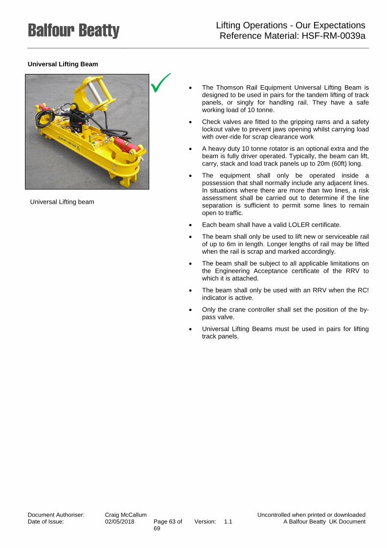
Lifting Operations - Our Expectations Reference Material: HSF-RM-0039a
Universal Lifting Beam
• The Thomson Rail Equipment Universal Lifting Beam is designed to be used in pairs for the tandem lifting of track panels, or singly for handling rail. They have a safe working load of 10 tonne.
• Check valves are fitted to the gripping rams and a safety lockout valve to prevent jaws opening whilst carrying load with over-ride for scrap clearance work
• A heavy duty 10 tonne rotator is an optional extra and the beam is fully driver operated. Typically, the beam can lift, carry, stack and load track panels up to 20m (60ft) long.
• The equipment shall only be operated inside a possession that shall normally include any adjacent lines. In situations where there are more than two lines, a risk assessment shall be carried out to determine if the line separation is sufficient to permit some lines to remain open to traffic.
• Each beam shall have a valid LOLER certificate.
• The beam shall only be used to lift new or serviceable rail of up to 6m in length. Longer lengths of rail may be lifted when the rail is scrap and marked accordingly.
• The beam shall be subject to all applicable limitations on the Engineering Acceptance certificate of the RRV to which it is attached.
• The beam shall only be used with an RRV when the RC! indicator is active.
• Only the crane controller shall set the position of the by-pass valve.
• Universal Lifting Beams must be used in pairs for lifting track panels.
Universal Lifting beam
Document Authoriser: Craig McCallum Uncontrolled when printed or downloaded Date of Issue: 02/05/2018 Page 63 of
69 Version: 1.1 A Balfour Beatty UK Document

Lifting Operations - Our Expectations Reference Material: HSF-RM-0039a
Sleeper Spacers
• The Hydraulic Variable Sleeper Spacing attachments (4 and 7 leg variants) - are designed for the high output unloading and laying of concrete and wooden sleepers. The telescopic frame structure make it small yet it’s easy adjustable to fit most types of current sleepers.
• Different clamps can be mounted on this machine, depending on the shape, length and nature of the sleepers to be handled. They can grip up to 7 sleepers at once.
• The main advantage of this machine is its ability to lay down the sleepers according to a chosen spacing, thanks to a simple adjustment, the operator can modify the spacing when needed (for example for curves or any other types of tasks).
• Lifted into position, their correct placement is assured by a precision gauging system that spreads the sleepers to the desired distance.
• The hydraulic telescopic arms work independently, so that sleepers of different lengths can be held safely. The 360o rotator drive provides endless slewing motions for reaching virtually any position.
• Each beam shall have a valid LOLER certificate.
• The Sleeper Layer must only be used by authorised and competent personnel in accordance with mandatory rules, regulations and the equipment operating instructions.
• If adjacent lines are open to traffic, it shall only be used in accordance with the Method Statement for the possession and only if the safe system of work has taken account of gauge exceedance.
• Staff shall be briefed on the safe operation of the machine prior to its use.
• The limitations of the RRV to which the machine is attached shall apply.
• It must not be used under live overhead line equipment or in live conductor rail areas.
Document Authoriser: Craig McCallum Uncontrolled when printed or downloaded Date of Issue: 02/05/2018 Page 64 of
69 Version: 1.1 A Balfour Beatty UK Document

Lifting Operations - Our Expectations Reference Material: HSF-RM-0039a
Thimbles
• Rail Thimble is suitable for use with BS113A, UIC60 and Bull Head rail sections.
• It is designed to be suspended from chain, hook or shackle from the host RRV boom.
• Rollers grip the rail securely under the head and support it during the threading operation. Grease nipples are fitted to each shaft to allow for lubrication of each roller.
• The hydraulic cylinder is fitted with a safety valve in case of hose failure.
• Using this thimble, long welded rail can be threaded into place ready for fastening or quickly removed from the rail seats for transposing.
• Where rails are to be moved by means of a rail thimble, the safe system of work shall incorporate adequate control measures for railway specific risks, see - “NR/L2/RMVP/0200/P005 - Handling new or serviceable rail with road-rail excavator cranes in rail mode” for detailed requirements.
• The shortest length of rail that can be moved with the thimble is 100 metres.
• Each thimble shall have a valid LOLER certificate.
• The thimble shall be subject to all applicable limitations on the Engineering Acceptance certificate of the RRV to which it is attached.
• The thimble shall only be used with an RRV whose the load on hook indicator (RCI) indicator is active, and the lifting duty is in excess of the beam/load in the most adverse condition.
• During the operation the RCI shall be monitored and the load shall not be allowed to exceed the Safe Working Load of the thimble or the lifting appliance.
• Note: This should be limited to a maximum of 2 tonne.
Document Authoriser: Craig McCallum Uncontrolled when printed or downloaded Date of Issue: 02/05/2018 Page 65 of
69 Version: 1.1 A Balfour Beatty UK Document
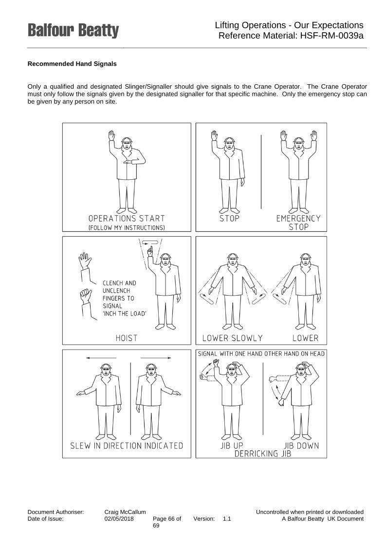
Lifting Operations - Our Expectations Reference Material: HSF-RM-0039a
Recommended Hand Signals
Only a qualified and designated Slinger/Signaller should give signals to the Crane Operator. The Crane Operator must only follow the signals given by the designated signaller for that specific machine. Only the emergency stop can be given by any person on site.
Document Authoriser: Craig McCallum Uncontrolled when printed or downloaded Date of Issue: 02/05/2018 Page 66 of
69 Version: 1.1 A Balfour Beatty UK Document
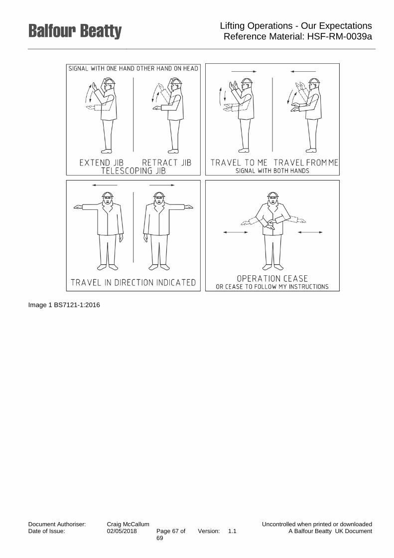
Lifting Operations - Our Expectations Reference Material: HSF-RM-0039a
Image 1 BS7121-1:2016
Document Authoriser: Craig McCallum Uncontrolled when printed or downloaded Date of Issue: 02/05/2018 Page 67 of
69 Version: 1.1 A Balfour Beatty UK Document

Lifting Operations - Our Expectations Reference Material: HSF-RM-0039a
Using Two Way Radio
Two way radio is extremely important to assist with communication between the Crane Operator and the Slinger/Signaller. A few simple rules must be followed.
• Ensure that the batteries in all handsets are fully charged and will last the whole operation
• Keep spare batteries on charge and ready for use.
• Keep communication limited to the operation taking place.
• Make the instruction brief and clear.
• Do not use inappropriate, foul or abusive language.
The following are standard words and uses during communication:
Affirmative Yes.
Negative No.
Reading you loud and clear I understand what you say.
Over I have finished talking and I am listening for your reply.
Out I have finished talking to you and do not expect a reply.
Roger I understand what you just said.
Copy I heard what you just said.
Wilco Will comply (after receiving new directions).
Go ahead Send your transmission.
Say again Please repeat your last message.
Break Signals a pause during a long transmission to open the channel for other transmissions, especially for emergencies
Standby Pause for the next transmission. This usually entails staying off the aid until the operator returns after a short wait.
When lifting operations are taking place the following words should be used. The Crane Operator will continue the request until given a further instruction.
Start Let the Crane Operator know you are ready to give instruction.
Stop Instructs the Crane Operator to stop and wait for the next instruction.
Lift Lift the load as instructed.
Document Authoriser: Craig McCallum Uncontrolled when printed or downloaded Date of Issue: 02/05/2018 Page 68 of
69 Version: 1.1 A Balfour Beatty UK Document

Lifting Operations - Our Expectations Reference Material: HSF-RM-0039a
Slew (Right/Left) Rotate the crane as instructed.
Lower Lower the load as instructed.
Jib (Up/Down) Lift or lower the jib as instructed.
Forward Travel forward as instructed.
Backward Travel backward as instructed.
Travel (Right/Left) Turn the crane as instructed.
Where continual communication is lost immediately stop all operations
Document Authoriser: Craig McCallum Uncontrolled when printed or downloaded Date of Issue: 02/05/2018 Page 69 of
69 Version: 1.1 A Balfour Beatty UK Document